The World's future
Innovations and New Technologies (v.2)
By Alexander Bolonkin
Dr.Sci., Professor of Russian and American Universities,
Former Senior Researcher of NASA, USA Air Force and Russian Aerospace Industry
New York, Lulu, 2013
The World's future
Innovations and New Technologies (v.2)
By Alexander Bolonkin
Dr.Sci., Professor of Russian and American Universities,
Former Senior Researcher of NASA,USA Air Force and Russian Aerospace Industry
Lulu, New Your, 2013
Book 5 Innovations and New Technologies 7 9 13
Contents:
About author 4
Abstract 5
Preface 6
Part 1. New Ideas and Innovations in Aerospace 7
1. Air Catapult Transportation 7
2. Hypersonic Ground Electric AB Engine 26
3. Protection of the Earth from Asteroids 42
4. Re-Entry Space Craft to Earth Atmosphere 49
5. Energy Transfers from Airborne Wind Turbines.
Review and Comparison of Airborne Turbines 61
6. Delivery of Asteroids to the Earth 88
7. Non Turbo Electric Wind Generator 102
8. Electron Air Hypersonic Propulsion 114
9. Long Distance Artillery 121
10. New Self-Propelled Penetration Bomb 134
11. Inexpensive Mini Thermonuclear Reactor 151
12.Hypersonic Space Aircraft 175
13. Method for Interstellar Flight 195
Part 2. New Ideas and Innovation in Space Sciences and Earth Technologies. 206
1. Universe. Relations between Time, Matter, Volume, Distance, and Energy.
Rolling of Space (Volume, Distance), Time, and Matter into a Point. 206
2. Underground Explosion Nuclear Energy. 215
3. Protection of Environment from Damaged Nuclear Station and Transparant Inflatable
Blanket for Cities (Protection from Radioactive Dust and Ghimical, Biological Weapons) 234
4. Electron Hydro Electric Generator 258
5. Hydro Propulsion for High Speed Submarines 266
6. Stability and Artificial Distraction of Tornado 273
7. Femtotechnology: Stability and Production Super-Strong AB Matter 283
8. Universe (Part 3). Relations between Charge, Time, Matter, Volume, Distance, and Energy 302
9. Electrostatic Generator and Electrostatic Transfomer 311
10. Jet Generator 322
11. Terroformatic of Planets and Space Objects 338
Appendix (Data) 362
General Reference 378
About the Author
Bolonkin, Alexander Alexandrovich (1933-)
Alexander A. Bolonkin was born in the former USSR. He holds doctoral degree in aviation engineering from Moscow Aviation Institute and a post-doctoral degree in aerospace engineering from Leningrad Polytechnic University. He has held the positions of senior engineer in the Antonov Aircraft Design Company and Chairman of the Reliability Department in the Clushko Rocket Design Company. He has also lectured at the Moscow Aviation Universities. Following his arrival in the United States in 1988, he lectured at the New Jersey Institute of Technology and worked as a Senior Researcher at NASA and the US Air Force Research Laboratories.
Bolonkin is the author of more than 250 scientific articles and books and has 17 inventions to his credit. His most notable books include The Development of Soviet Rocket Engines (Delphic Ass., Inc., Washington , 1991); Non-Rocket Space Launch and Flight (Elsevier, 2006); New Concepts, Ideas, Innovation in Aerospace, Technology and Human Life (NOVA, 2007); Macro-Projects: Environment and Technology (NOVA, 2008); Femtoyechnologies and Revolutionary Projects, (Lambert, 2009); Human Immortality and Electronic Civilization, 3-rd Edition, (Lulu, 2007; Publish America, 2010); Universe, Human Immortality and Future Human Evaluation. Elsevier. 2011г., 124 pages, 4.8 Mb.; LIFE. SCIENCE. FUTURE (Biography notes, researches and innovations). Publish America, Baltimore, USA, 2010, 208 pgs.
Abstract
In recent years of the 21st Century the author of this book and other scientists as well, have instigated and described many new ideas, researches, theories, macro-projects, USA and other countries patented concepts, speculative macro-engineering ideas, projects and other general innovations in technology and environment change. These all hold the enticing promise for a true revolution in the lives of humans everywhere in the Solar System.
In aerospace these include air catapult transportation, hypersonic ground electric AB engine, protection of the Earth from asteroids and delivery of asteroids to the Earth, re-entry space apparatus to Earth, airborne wind turbines, electronic wind generator and propulsion, long distance shells, new self-propelled penetration bomb, inexpensive mini thermonuclear reactor, etc.
In technology these include new ideas and innovation in space sciences and Earth technologies: Relations between time, matter, volume, distance, and energy in the Universe; Rolling of Space (volume, distance), time, and matter into a point; Underground explosion nuclear energy; Protection of environment from damaged nuclear station; Electron hydro electric generator; Electron super speed hydro propulsion; Electric theory of tornado; Protection from tornado; and so on.
Author succinctly summarizes some of these revolutionary macro-projects, concepts, ideas, innovations, and methods for scientists, engineers, technical students, and the world public. Every Chapter has three main sections: At first section the author describes the new idea in an easily comprehensible way acceptable for the general public (no equations), the second section contains the scientific proof of the innovation acceptable for technical students, engineers and scientists, and the third section contains the applications of innovation. And, naturally, he fervently hopes the popular news media, various governments and the large international aerospace and other engineering-focused corporations will, as well, increase their respective observation, R&D activity in the technologies for living and the surrounding human environment.
Key words: Universe, transportation, energy, nuclear energy, aerospace, non-rocket space launch and flight, environment.
Preface
New macro-projects, concepts, ideas, methods, and innovations are explored here, but hardly developed. There remain many problems that must be researched, modeled, and tested before these summarized research ideas can be practically designed, built, and utilized--that is, fully developed and utilized.
Most ideas in our book are described in the following way: 1) Description of current state in a given field of endeavor. A brief explanation of the idea researched, including its advantages and short comings; 2) Then methods, estimation and computations of the main system parameters are listed, and 3) A brief description of possible applications--candidate macro-projects, including estimations of the main physical parameters of such economic developmental undertakings.
The first and third parts are in a popular form accessible to the wider reading public, the second part of this book will require some mathematical and scientific knowledge, such as may be found amongst technical school graduate students.
The book gives the main physical data and technical equations in attachments which will help researchers, engineers, dedicated students and enthusiastic readers make estimations for their own macro-projects. Also, inventors will find an extensive field of inventions and innovations revealed in our book.
The author have published many new ideas and articles and proposed macro-projects in recent years (see: General References). This book is useful as an archive of material from the authors' own articles published during the last few years.
The book mainly contains material from the author's articles published in the last few years.
Every chapter is independent. Than why some figures are repited.
Acknowledgement
1. Some data in this work is garnered from Wikipedia under the Creative Commons License.
2. The author wish to acknowledge Professor Shmuel Neumann and Jorseph Friedlander for help in editing of
this book.
Part 1.
New Ideas and Innovations in Aerospace
Chapter 1.
Air Catapult Transportation
Abstract
The current flight passenger-transport and cargo systems have reached the peak of their development. In the last 30 years there has been no increase in speed or reductions in trip costs. The transportation industry needs a revolutionary idea, which allows jumps in speed and delivery capability, and dramatic drops in trip price. The author offers a new idea in transportation in which trip (flight) time practically does not depend on distance, and vehicle load capability doubles and which has a driving engine that is located on the ground and can use any cheap source of energy.
The author develops the theory and provides computations for a project containing five subprojects united by the common idea: acceleration the air vehicle on the ground and continuation of flight by inertia (high speed catapulting). The initial speed is 290 - 6000 m/s, the range is 50 -10000 km (short, average, and long distances). Short transport system has a range on the order of 50-70 km, for example: city - sub-city, strait and air bridges such as across the Straits of Gibraltar 16 km, the English Channel 40 km, Bering Straits 100 km (Russia-America), Sakhalin-Asia 20 km, Russia-Japan, etc. The long distance has range up 10000 km such as New York-Paris 5838 km, Washington-London 7373 km, San-Francisco - Tokyo 8277 km, San-Francisco - Vladivostok (Russia) 8377 km, New York - Moscow 7519 km, Moscow - Beijing 5800 km, Moscow - Tokyo 7487 km, New York - Berlin 6392 km, and so on.
The offered catapult system having a length of 400 km can be used as a space launch system which decreases the space launch cost by hundreds of times. This also may be used as a new conventional high speed (up 1000 km/h) transport system between cities. That will be significantly cheaper then used MagLev (Magnetic Levitation) systems, because for levitation of the vehicle we employ conventional wings. The offered system may be also used for the mass launch of bombs (projectiles) in war.
-------------------
Key word: air catapult transport, air kinetic transport, new passenger and cargo transport, catapult aviation, new space launch system, new suspending high speed ground system, cattran, skimplane.
Introduction
Current takeoff mass of a long distance aircraft is made up of approximately 1/3 aircraft body, 1/3 fuel, and 1/3 payload. The aircraft engine needs expensive aviation fuel. The passenger-transport aircraft cannot exceed the speed of sound. The history of "Concorde" shows that the conventional passenger supersonic aircraft is unprofitable [1]. The hypersonic aircraft, which is under development by the USA, will be more unprofitable still as a passenger long distance aircraft because it will use very expensive hydrogen fuel, it is very complex and it has a high production cost. The hypersonic engine problems have not been solved in spite of spending large multiples of millions of dollars in research and testing. Space launch by the current rocket space system is very expensive. The current high speed (up to 580 km/h) MagLev (Magnetic Levitation) transport systems are also very expensive.
Transport, space launch systems and aviation all need new ideas that increase speed, and load capability, and reduce delivery cost. Some of these ideas have been published by the current author [1-11].
The initial author's idea is the acceleration (catapulting) of a cargo glider (vehicle), winged cargo box (non-engine aircraft), or space ship to high speed by using a cable engine. It was offered in 2002 [2] - [7], in particularly, it was presented in [1] and published in [8]. The current research is different because it uses a linear electric engine located on the ground. The vehicle will then use its kinetic energy for flight. The computation shows that a catapulted/kinetic aircraft accelerated to subsonic speed of 270-300 m/s can fly up to 60-80 km until its speed decreases to a landing speed of 50-60 m/s. This is far enough for suburban transport or for air bridges across the Straits of Gibraltar, English Channel, Bering Straits (Russia-America), Sakhalin-Asia, Russia-Japan, etc. For acceleration to this speed at a rate that is acceptable to passengers (overload of 3g) the runway length must be 1.5 km (current runways for large aircraft are 1.5 - 3 km long). For the middle range (200 - 1600 km) the runway must have a length of 4 - 67 km. For the long-distance flight (6000-8000 km), the air vehicle must be accelerated to a speed of 4-6 km/s. For acceleration of no more than 3g the required runway length would then be 270 - 400 km. This runway can be also used for a space launch. One author method and design are described in References [5, 8]. Rather than being a conventional runway, it is an air cable acceleration system [5] - [8] for the acceleration of space vehicles and it is located in atmosphere.
The offered method is different from conventional MagLev because for levitation of the vehicle we employ the conventional wing (no magnetic levitation!). That is significantly cheaper. The offered system has also smaller financial risk because it is uses conventional technologies and in any case one may be used in the place of a conventional ground high-speed transport system between big cities, opening a large market.
Brief description of the innovation
The system for catapult/kinetic vehicles (CV/KV) includes Figure (1) a runway having the linear electric engine (LEE) [1], [9]. The runway may be located on ground or over columns. The LEE can be located under the runway cover. In this case the runway may be used as a conventional aircraft take-off way (runway) or a car highway (quite straight) and may double as a launcher. At speeds over 50 m/s (180 km/s) the catapult vehicle supported by its wings and does not have friction with ground. As computations show, the length of runway is 1400 m for the subsonic vehicles having range 50-70 km; 4 - 67 km for the supersonic vehicle having range 200 - 1600 km; and 270 - 600 km for hypersonic vehicles having range up 10,000 km (and more) for acceptable (for conventional passengers) acceleration 3g. Trained astronauts/cosmonauts can tolerate a "G" overload of up to 9g and their starting runway can be 400 km for a final speed of 8 km/s. For cargo space ships the runway will be significantly lower (because of higher G tolerance). The part of runway, where vehicle has supersonic or over Mach 1 speed may need reflectors, which will reflect the shock wave (sound boom). The system has a starting trolley where the catapulted vehicle is supported during launch. After release this trolley brakes at high deceleration and the additional braking distance is small. This part of spent energy is retuned back into the system.
This system is significantly cheaper than MagLev because it does not need the expensive magnetic suspension system. Rather than expensive liquid fuels, it uses cheaper electric energy. The vehicles save greatly on expensive engines.
The system works in the following way. The catapult vehicle (aircraft without engines, wing container) located on the start trolley, accelerates (overload n = 3g), separates from trolley, climbs to the needed altitude (one may has the vertical overload n = 3g), flies (using its kinetic energy, gradually loses speed and increases its attack angle or/and wing area), glides and lands as a conventional aircraft.
Figure (1). Trajectories of the catapult vehicles (kinetic/ballistic vehicle, aircraft). (a) Short distance (up 70 km) subsonic vehicle (city - sub-city. Strait, mountain); (b) Middle distance (up 1500 km) supersonic vehicle (between cities); (c) Long distance (intercontinental, outer space) hypersonic vehicle, (space ship, satellites, probes). (d) Hypersonic vehicle with rebound from atmosphere. Notations: 1 - start, acceleration station; 2 - Climb to altitude; 3 - flight into atmosphere (subsonic and supersonic vehicles), or outer space (hypersonic vehicle; 3a - flight with rebound from atmosphere; 4 - gliding in atmosphere; 5 - trajectory, 6 - surface, 7 - boundary of atmosphere (- 80 - 100 km).
The range strongly depends upon the ratio K = lift/drag. The subsonic civil aircraft has K - 12 - 20 (gliders have K up 70). For example, Boeing-747 has K = 17 [19]. The supersonic aircraft in the range Max number M = 1.5 - 4 has K - 6 - 8. For example, Concord has K = 7.14 [8]. The hypersonic aircraft has K - 4 - 4.5. Approximately K = 4(1+3/M) for M > 1.5, where M is Mach number. The special catapult aircraft will have K of (1 - 3) more because one does not have the motor gondolas (drag inducing engine mounts). A good trajectory is a trajectory when aircraft climbs to high altitude and glides. The hypersonic CV may reach rarefied heights or out of atmosphere and significantly increase the range. It is very useful if the aircraft has the variable swept and wing area. Many current supersonic aircraft have these properties (B-1, Tu-160) [8].
The subsonic CV starts from a conventional aerodrome equipped by LEE, and is accelerated (with 3g) up to a speed of 270-300 m/s (Mach number 0.9) by the linear electric engine into the runway which is 1500-1800 m long Figure (1). The aircraft takes off, flies (50-70 km, Fig. (1a)), gradually loses speed and increases its attack angle and extend the flaps. When the speed drops so it is close to landing speed, the aircraft extends the landing gear and lands. At first modified old aircraft (without engines and engine nacelles) can be used for early versions of the offered transport system.
The range of the high-speed aircraft may reach 200-10,000 km (or more) see Figure (3). The aircraft can make a full circle and return to its base. The flight data are drastically improved if the vehicle has variable wing area or variable swept wings [5]. Other similar ideas and useful points for kinetic aviation are presented in References [5 - 8]. The flight altitude does not its influence range because the energy spent in climbing will be returned in gliding.
This new type of -+transportation the author names as Cattran (Catapult transportation).
Theory of catapult transport (Cattran) and a general estimation of flight data
(In metric system)
-
The maximum range, R, of kinetic air vehicles is obtained from the kinetic energy of theoretical mechanics for K = const. It equals
(1)
where R is range [m]; R0 = 6,378.106 is the Earth's radius [m]; K is the average aerodynamic efficiency (K = 10 - 22 for subsonic air vehicles and K = 5-8 for supersonic air vehicles. For example: the subsonic Boeing-747 has maximum K = 17; Tu-104 K=18; B-1, Tu-160 K > 19 (in subsonic regime); Boeing 47E K = 20; Boeing B-52G K = 21.5; Rutan Voyager K = 27, Lockheed U-2 K = 28; M-17 (high altitude aircraft) K = 30; gliders have K = 40 - 70; the supersonic "Concorde" has maximum K = 7,5, supersonic aircraft XB-70 and YF-12 have K = 7, and Boeing 2707-300 has K = 7.8 ); go = 9.81 m/s2 is gravity [8]; V1 is initial (after acceleration) speed [m/s]; V0 < V1 is final (near landing) speed [m/s] (V0 = 50-60 m/s); V is variable speed, V0 < V < V1 [m/s]. For estimation average V = 0.5(V1+V0); mg/K = D is air drag [N]; m is vehicle mass [kg]. For V < 2000 m/s, variable gravity g - go. Last equation in (1) is obtained from the first equation using integration.
The ratio K approximately equals:
(2)
Here M is Mach number; L is wing span, m; S is wing area, m2; a is sound speed, at H = 0, T = 0oC a = 330 m/s; for T = 20oC a = 342 m/s. For H > 11 km a - 295 m/s; Cd,0 - 0.008 - 0.012 is the vehicle drag coefficient for attack angle = 0.
Results of computations for subsonic (V < 300 m/s, M < 0.9, M is Mach number) and supersonic vehicles are presented in Figures (2&3). The range of a subsonic vehicle is 45 - 90 km for V1 = 300 m/s Figure (2); the range of a supersonic vehicle can reach 4000 - 8200 km for V1 = 4500 m/s (figure.3).
2. Maximum acceleration sub-distance 1 (S) Figure (1) and required energy (E) (only for acceleration - that is main part of common energy) can be calculated using the equation
(3)
where n is overload, g; m is vehicle mass, kg.
Results of computations for subsonic and supersonic aircraft are presented in Figures (4 & 5).
Figure (2). Range of the subsonic catapult (kinetic) vehicle versus initial speed for different aerodynamic efficiency K = 10 12 14 16 18 20.
Figure (3). Range of the supersonic catapult vehicle versus initial speed for different aerodynamic
efficiency K = 4 5 6 7 8.
Figure (4). Acceleration distance of subsonic catapult vehicle versus initial speed and different overloads.
Acceleration (3g) distance is 1500 m for a speed of 300 m/s for the subsonic vehicle and 340 km for a speed of 4.5 km/s for the supersonic vehicle.
Figure (5). Acceleration distance of supersonic catapult aircraft versus initial speed and different overload.
3. Average speed, Va, and flight time, T, are
(4)
The results of computation of eq.(4) are presented in Figures (6 &7). The subsonic vehicle has an average speed 1.5 times greater than conventional aircraft (because the catapult vehicle has high subsonic speed of the beginning), and the average speed of the supersonic (hypersonic) vehicle is more than 6-9 times that of a conventional subsonic vehicle. The flight time is less for both cases.
Figure (6). Average speed of the kinetic/catapult and conventional vehicle versus range for differentaerodynamic efficiency K = 4 5 6 7 8.
Figure (7). Average flight time of the kinetic/catapult vehicle and conventional aircraft versus range.
4. The trajectory of horizontal turn can be found from the following differential equations
(5)
where L1 is the projection of the vehicle lift force to a horizontal plane (vertical overload is n = 3g); t is time [seconds]; ? is turn angle [rad].
Results of computations for different overloads show that the vehicle can turn back and return to its original aerodrome (for example, the transport/passenger vehicle in emergency case or a bomber after a flight into enemy territory) (see [1], [8] p.366, figs. A.2.8-9).
5. Computation of the complex trajectory used for high altitude and outer space.
Accurate equations of ballistic trajectory are:
(6)
For subsonic speed (M < 0.9)
L = 0.5CL ?V2S, D =0.5CL ?V2S , g = go ,
For supersonic (M > 1.5) and hypersonic speed
L = 0.5CL ?aVS, D = 0.5CD ?aVS, g = go(Ro/R)2,
where r is range of ship flight, m; R0 = 6,378,000 is radius of Earth, m; R is radius of ship flight from Earth's center, m. R = Ro+H; V is ship speed, m/s; H is ship altitude, m; ? is trajectory angle, radians; D is ship drag, N; m is ship mass, kg; g is gravity at altitude H, m/s2; L is ship lift force, N; ?E = 7.27.10-5 is angle Earth speed, rad/sec; ?E = 0 is lesser angle between perpendicular to flight plate and Earth polar axis; t is flight time, sec.; CL is lift force coefficient, for subsonic speed CL = 0 - 3.5 , for supersonic speed CL - 4? , where ? is the wing attack angle, rad; CD is air drag coefficient. For supersonic wing CD - ?2; a - 295 m/s for H > 11 km is sonic speed in atmosphere; S is wing area, m2; ? is the air density, for H = 0 ?o = 1.225 kg/m3. For H = 0 - 100 km ? - ?o exp(-1.4.10-4).
6. Estimation of range: The computation of equation (5) requests the complex numerical integration. For estimation of climb range (sub-distance 2 in Figure (1) can be used the simpler equation
(7)
where g - 10 m/s2 Earth gravitation; n = 3 - 9 vehicle overload; K = L/D is the ratio lift/drag. For subsonic speed (M < 0.9) K - 17 - 22, for supersonic speed (M >1.5) K - 4(1+3/M), where M = V/a is Mach number. The ratio K for subsonic aircraft is significantly more than K for supersonic aircraft. The way for large range at the start is to get a high altitude and glide from it (fig.1b). For the same reason after entering to atmosphere from vacuum it may be useful to bounce off the atmosphere and return to vacuum Figure (1d). It is also useful for cooling of vehicle.
Sub-distance 3 (flight out Earth atmosphere, H >- 80 -100 km) can be computed by equations:
(8)
where L3 is sub-distance 3 (fig.1) (flight out Earth atmosphere, H >- 80 -100 km), m; ? is Earth angle, rad; Va is vehicle speed at the exit from atmosphere, m/s; ?a is trajectory angle at the exit from atmosphere; ?a,opt is optimal trajectory angle (maximal range of sub-distance 3) at the exit from atmosphere.
7. Estimation of heating: The magnitudes in equations (5)-(6) for hypersonic speed compute as:
(9)
where: g0 = 9.81 m/s2 is gravity at Earth surface; ? is air density, kg/m3; Q is heat flow in 1 m2/s of leading sharp, J/s.m2; S is wing area, m2; ?SL= 1.225 kg/m3 is air density at sea level; VCO = 7950 m/s is circle orbit speed; T1 is temperature of leading edge (tip) in stagnation point in Kelvin, oK; T is temperature of leading edge in stagnation point in centigrade, oC; T2 is temperature of the standard atmosphere at given altitude, oK; D is vehicle drag, N; L is vehicle lift force, N; CD is drag coefficient; a = 295 m/s is sound speed; CS = 5.67 W/(m2.K4) is coefficient radiation of black body; ? is coefficient of a black (? - 0.03 - 0.99).
For speed less than M = 3 (V < 900 m/s) the heating of the leading edge from a shock wave is small. For example, for Concord and Ty-144 it is about 127oC [8]. The aluminum alloys can resist 175oC. But for hypersonic vehicle that heat may reach 1500oC. But for the offered vehicle that is not a problem. The current material can keep up to 2500oC, the leading edge is under this temperature a shot time (about only 40 seconds), that can require only a small cooling. The problem of heating for re-entry apparatus such as Shuttle and Apollo and the catapult vehicle is opposite. The re-entry apparatus must SPEND its gigantic kinetic energy as soon as possible (to brake). That way Shuttle has a BLUNT (obtuse) fuselage and wing edge, which give a high air drag. That gives a very high heat flow. Our vehicle must CONSERVE the kinetic energy. One has a sharp fuselage and wing edge, which has a small air drag and small heat flow [9, Chapter8].
The Shuttle must decrease speed from 8000 m/s to zero (Apollo must lose 11 km/s). Our vehicle loses only 500 -1000 m/s during lifting (climbing) in atmosphere. That means one get a specific heat (in 1m2) of 500 - 4000 times less than Shuttle. The flight time of Shuttle in dense atmosphere is tens of minutes, our vehicle - only 40 sec. [17, Chapter 4].
8. Linear electric engine: Linear electric (magnetic) engines (LEE) exist in various forms. They are widely used for subsonic Maglev. The record speed of MagLev is 581 km/h (2011), the railroad is 575 km/h. Some hypersonic LEEs are offered and researched by author in [10] Chapter 8, [11], [14-16]. The new linear electrostatic engine was offered by author in [17].
9. Levitation of vehicle. The current railroad wheels cannot support high-speed vehicles because the centrifugal force of wheels is very large. For supporting vehicle was suggested magnetic force (as Maglev) or an air cushion (as hovercraft). Author offers the new method of the ground vehicle levitation by lift from wings. That is very simple. The ratio K = L/D can be up 100 and more. The specific feature of offered apparatus from flarecraft, sea skimmer, ekranoplan, is next: ekranoplan and others has engine located in apparatus and they can fly anywhere. The offered apparatus has engine located at ground level and moves only over a special track. One version has the ability to run only on special flat, smooth way (as Maglev) with very high K. Therefore I name that version the Skimplane.
Advantages
The offered method has the following advantages:
The load capability of catapult vehicle increases as a factor of two in comparison with
conventional aircraft (no fuel or engine in the catapult vehicle. Fuel mass reaches 30 - 40%, engine mass is about 10% of total conventional aircraft mass).
The catapult vehicle (cattran) is significantly cheaper than conventional aircraft (no aviation engines, which are very expensive and have limited engine life: 2000-9000 hours. The aircraft body has a lifetime of 20-30 years). In with ground transport, we don't need expensive bridges, tunnels, roads.
The linear electric engine located on the ground can work on cheaper electric energy.
The average speed for long-distance travel is increased by 6-9 times see Figure (6).
The maximum flight time is about 34 min for a distance at 10,000 km (see Table 3 and Figure (7)).
The flight article production cost is dramatically reduced.
One installation can have a very large capability and can serve many airlines, for example, most airlines from the USA to Europe (New York to London, Paris, Berlin, Madrid, Brussels, Fan Francisco - Tokyo, Shanghais, etc). The load capability is also increased greatly.
The installation can be used to launch outer space passenger and cargo ships, satellites and probes (some accelerator projects currently offered use conventional airplanes as a Stage 0 booster but they have a maximum speed of only 270 m/s).
The installation can be used for space tourism and flights along high altitude ballistic trajectories.
The installation can be used as conventional very high-speed ground transport between big cities (skimplane).
The installation can be used for mass launch of military projectiles in wartime.
Projects (Cattran, Skimplane)
The offered project contains only the well-known technologies. The risk is small. The full project contains the 4 subprojects. The realization of this project is best to start from the cheapest subproject 1, which allows getting the experience for more complex subprojects.
Subproject 1. Subsonic speed sort distance (50 -70 km) catapult passenger vehicle (for city and sub city, straits, mountains, and etc.).
There are a lot of islands in the world, located close to one another or located close to a continent, which have large transportation flows. For example:
-
Straits of Gibraltar (16 km); connects Europe with Africa.
-
English Channel (40 km); connects England with Europe.
-
Sicily and Italy (5 km).
-
The Dardanelles (from 2 to 5 km).
-
Various Japanese Islands.
-
Taiwan with mainland China (25 km).
-
Bering Straits (100 km) (Russia and America).
-
Sakhalin-Asia (20 km) (Russia).
Assume the mass of the passenger vehicle is m = 15 tons (100 passengers and 4 members of crew); the start acceleration is a = 3g - 60 m/s2 (this acceleration is acceptable for conventional people). The range is approximately 67 km (see Fig. 2) or calculate using R - KV2/2g = 67.3 km for a final acceleration speed of 290 m/s and K = 16, g = 9.81 m/s2.
The required acceleration distance is about S = V2/2a =1400 m. The time of horizontal acceleration is t = V/a = 9.7 seconds. The energy required for acceleration of the aircraft is E = mV2/2. This is about E=0.63.109 Giga joules (1 Giga joules = 109 J) if V = 290 m/s. A power is about P = E/t = 0.63.109/ 9.7- 65,000 kW. If the engine efficiency is ? = 0.95, the energy consumption will be F = E/? = 0.63.109/0.95 = 0.66 GJ per flight or 6.6 MJ per one passenger. As it is shown below the 1 MJ of electric energy cost 0.00877$. Therefore the energy spent by 1 passenger will be cost 6.6.0.00877 = 0.0578$ or about 6 cents.
Flight time is about 394 sec or 6.57 minutes. In present time the car or train requires at distance 67 km about 1 hour and in traffic it is requires significantly more time.
Summary of the main results: For the start speed - 300 m/s, landing speed - 50 m/s, maximal range 70 km, average speed 175 m/s = 630 km/h, flight time - 400 sec = 6.7 min, acceleration distance for overload 3g is 1500 m, acceleration time is 10 sec.
Subproject 2. Supersonic speed catapult passenger vehicle for distance 200 - 1500 km.
Distance between main cities are: New York - Washington 329 km, London-Paris 344 km, Berlin-Warsaw 517 km, Moscow-St.-Petersburg 653 km, Moscow-Kiev 756 km, Berlin-Paris 878 km, Paris-Madrid 1054 km, Tokyo-Vladivostok 1157 km, Tokyo-Seoul 1157 km, Rome-Berlin 1185 km, Rome-Madrid 1365 km.
Assume the mass of the passenger vehicle is m = 15 tons (100 passengers and 4 members of crew); the start acceleration is a = 3g. The result of computations in the trajectory #2 (climbing of altitude up speed 270 m/s and gliding with ratio lift/drag K = 20) are presented in Table 1. Used equations are (7).
Table 1. Computations of supersonic catapult passenger vehicle for range 200 - 1500 km. Overload is n = 3g.
|
Initial speed V, m/s |
500 |
600 |
700 |
800 |
900 |
2000 |
|
Range L, km |
193 |
269 |
360 |
458 |
571 |
1550 |
|
Altitude Hmax, km |
5 |
8,5 |
12.7 |
17.3 |
22.5 |
30 |
|
Flight time T, min |
11 |
15 |
20 |
26 |
32 |
40 |
|
Acceleration Distance S, km |
4.167 |
6.009 |
8.167 |
10.67 |
13.5 |
66.7 |
|
Acceleration time Ta, sec. n=3g |
16.7 |
20 |
23.3 |
26.7 |
30 |
66.7 |
Subproject 3. Catapulted hypersonic speed passenger vehicle for distance 4000 - 10000 km.
The distance between main cities are (aircraft great circle courses are not straight lines): New York-Paris 5838 km, Washington-London 7373 km, San-Francisco - Tokyo 8277 km, San-Francisco - Vladivostok (Russia) 8377 km, New York - Moscow 7519 km, Moscow - Beijing 5800 km, Moscow - Tokyo 7487 km, New York - Berlin 6392 km.
Assume the mass of the space vehicle is m = 15 tons (100 passengers and 4 members of crew); the acceleration is a = 3g (this acceleration is acceptable for conventional people). Results of computation in Trajectory 3 (climbing of altitude 100 km, ballistic flight in space and gliding with ratio lift/drag K1 = 4.5 up V = 290 m/s and K = 20 for V < 290 m/s) are presented in Table 2. Equations are (6) - (7).
Table 2. Computations the hypersonic catapult passenger vehicle
for range 4000 - 10,000 km. Overload n = 3g.
|
Initial speed V, m/s |
4000 |
5000 |
6000 |
|
Speed at altitude 100 km, m/s |
3076 |
4148 |
5215 |
|
Range L, km |
3909 |
7035 |
10700 |
|
Flight time T, min |
21 |
28 |
34 |
|
Acceleration Distance S, km. n=3g |
267 |
416 |
600 |
|
Acceleration time Ta, min. n=3g |
2.2 |
2.8 |
3.3 |
Flight time (NY - Paris, range 5838 km) is about 25 minutes. In present time the trip NY - Paris takes about 7 hours. The required acceleration distance is S = 340 km. The time of horizontal acceleration is t = V/a =V/3g = 150 seconds = 2.5 minutes (see also Reference [7]).
As you see for acceleration up to hypersonic speed requires a special launch track having a linear electric engine and the special trolley (cart) where the catapult vehicle is located. A small additional way is required for braking this cart at high G. This launch track may be used:
1) For very high speed transportation between cities.
2) As cheap space launcher.
Subproject 4. A high speed (up 1000 km/h) ground transport system between cities (skimplane).
There are a lot of conventional projects for high speed transportation between cities. For our case are suitable city pairs: New York - Washington 329 km, Berlin-Warsaw 517 km, Moscow-St.-Petersburg 653 km, etc.
Economical efficiency
The conventional railroad costs about 0.8 - 1.3 M$/km (in permafrost (Siberia) - 11M$/km), highway system (8 lanes) 30 M$/km (USA), sea bridge 50- 80 M$/km, underground tunnel about 200 M$/km (English-France $12B, 50 km, 240 M$/km), Maglev about 25 M$/km.
Our system does not have a magnetic suspending system and one will be cheaper than MagLev. In present time the significant part of the passenger ticket cost is the cost of fuel. In aviation, car and bus this fuel percentage of cost reaches up 50%. For comparison of different transport systems we compute the cost of energy receiving from dissimilar types of fuel and the cost of delivery of one passenger to one kilometer by different types of transportation.
In Table 3 the reader will find the approximate costs of the different form of energy converted to mechanical energy.
Table 3. Average cost of mechanical energy for different fuels.
|
No |
Fuel |
Price, |
Energy, |
Price of |
Conv. |
Cost of mech. |
|
1 |
Oil, $100/barrel (159 liter) |
0.44 |
35.106 |
0.0126 |
0.3 |
0.042 |
|
2 |
Liquid1 (avia, bus)(USA) |
1 |
43.106 |
0.0233 |
0.3 |
0.0775 |
|
3 |
Electricity2 (wholesale) |
0.03$/kWh |
- |
0.00833 |
0.95 |
0.00877 |
|
4 |
Natural gas3, $0.4/m3(Rus) |
0.55 |
45.106 |
0.0122 |
0.3 |
0.041 |
|
5 |
Coal |
0.04 |
22.106 |
0.0018 |
0.3 |
0.006 |
Quote sources: Internet, Cost of fuel, December 2011.
Notes: 1. Price of the wholesale aviation (turbojet) fuel and an average retail price of gas/diesel fuel for car/bus in the USA.
2. Average wholesale price in the USA. Retail price is $0.065/kWh.
3. Russia sells natural gas to Europe $400/1000 m3 (2011).
As you see the cost of a unit of the electric energy in 9 times is less than aviation liquid fuel. The aviation, cars, buses, and most military vehicles can work only by liquid fuel, but the electric power plant can be hydro, wind, and nuclear power installations. This is an advantage for countries wishing to cut oil imports.
Method estimation of the cost of fuel for moving one passenger (100 kg) per the distance 1 km by the conventional transport (aviation, bus, railroad, sea ship) and cattran, skimplane.
1. Energy required for moving one passenger (100kg) per the distance 1 km by conventional transport and skimplane
(10 )
where Ev is energy requested for moving 100 kg of the loaded vehicle per 1 km = 1000 m [J/km]; m is mass of vehicle, 100 kg; g = 9.81m/s2; D = 1 km = 1000 m is distance; K = L/Dr is ratio of lift force to drag of the vehicle; Ep is energy required for moving one passenger per 1 km, J/man.km; b = mp/m is ratio of total mass passengers to total mass of vehicle (load coefficient); C is cost of fuel for moving one passenger to distance 1 km; c is cost of energy.
2. Energy required for moving one passenger (100kg) per the distance 1 km by catapult transport (cattran)
(11 )
where Vm is the maximal speed of catapulting, m/s; Df is distance of full flight, km.
For the sea ship the equations in (10) are
(12 )
Here N is power of engine, W; V is ship speed, m/s; W is displacement of the sea ship, kg.
The results of computation are presented in Table 4.
Table 4. Average cost of fuel for moving one passenger (100 kg) per distance 1 km by conventional,
catapult transport (cattran) and skimplane
|
# |
Type of transport |
Speed, m/s or km/h |
Rang, km |
Ratio |
b,Load coeff. |
Ev, J/kg.km |
Ep , J/man.km |
c, $/106J |
C, $/man.km |
|
1 |
Aviation |
270/972 |
7000 |
15 |
0.3 |
6.7.104 |
2.22.105 |
0.0775 |
0.0172 |
|
2 |
Cattran, subsonic |
170/612 |
60 |
15 |
0.5 |
6.1.104 |
1.22.105 |
0.00877 |
0.00123 |
|
3 |
Cattran, supersonic |
1500/5400 |
1500 |
7 |
0.5 |
7.5.104 |
1.5.105 |
0.00877 |
0.00132 |
|
4 |
Cattran, hypersonic |
5000/18000 |
7000 |
5 |
0.5 |
1.78.105 |
3.56.105 |
0.00877 |
0.00312 |
|
5 |
Skimplane |
270/972 |
- |
20 |
0.5 |
5.104 |
1.105 |
0.00877 |
0.00087 |
|
6 |
Bus1 |
28/100 |
- |
15 |
0.176 |
6.7.104 |
3.81.105 |
0.0775 |
0.0295 |
|
7 |
Railroad2(electr) |
28/100 |
- |
20 |
0.19 |
5.104 |
2.63.105 |
0.00877 |
0.00264 |
|
8 |
Sea ship3 (diesel) |
8.57/31 |
- |
201 |
0.0074 |
0.5.104 |
6.8.105 |
0.042 |
0.0292 |
Notes: 1. Bus has 60 passengers; total mass of bus is 28 tons.
2. Wagon has 54 sleeping places; total mass of the empty wagon is 23 tons.
3. Sea ship has displacement 14660 tons, engine 6252 kW, passengers 1078.
As you see the fuel cost of delivery of one passenger to one kilometer by cattran is 5.5 times less than long distance aviation and in 14 times less than by middle range aviation. The fuel cost of the delivery passengers from a sub-city to city by the subsonic cattran is 24 times less than a bus.
At the present time the fuel cost is 20 - 50% of a ticket cost in aviation, bus and ship. The real consumption of fuel for Boeing-747 (M = 0.9) is 0.031 liter/passenger.km, for supersonic (M = 2) and for Concord the fuel consumption is 0.166 liter/passenger.km [8] which explains why the Concord is not profitable. Fuel prices change with time, but in any case the cost of delivery will be some times less than delivery by conventional aircraft. Critics must remember that the main content of this article is not economic estimations, but the new idea for transportation, aviation and space launch.
Discussion of Problems
-
Vehicle heating. The proposed hypersonic vehicle will experience heating from compressed air. The space ship Space Shuttle and warheads of ballistic rockets have the same problem and in more difficult form because they have greater maximum speed (about 8-11 km/s). The heat flow increases by more than a third power of speed as V 3.15. This problem is successfully solved by a demountable terminal cover on Space Shuttle and on warheads. The same solution may apply in the proposed catapult vehicle (CV). The other solution is cooling, but that needs additional research. The nose and the leading edges of the wing of Mach 2 aircraft have temperature 127oC and do not need cooling because the current aluminum alloys keep the temperature up 175oC. If speed is 3, the leading edges of aircraft flying a long time has been used stainless steel (XB-70 Valkyrie) or titanium (SR-71) [19]. The cattran flights are for a short time in atmosphere with a high speed. Middle range cattran decreases speed to subsonic at high altitude. The long range hypersonic cattran quickly reaches outer space.
If speed is less than 5-7 Mach, the catapult vehicles (the leading edges) can be made from heat-resistant material. If the speed is more than Mach 7, the hypersonic CV may need to have a cooling system. However, this problem is not as difficult for catapult vehicles as it is for the Space Shuttle. The problems of the Space Shuttle and the CV are different. The Space Shuttle has much greater speed (about 8000 m/s) and kinetic energy, and needs to reduce this speed and energy by air drag. For this the Space Shuttle has an obtuse (blunt) nose and leading edges of the wings. The CV must conserve its speed and energy for the long flight. The CV has a sharp nose and leading edges of the wings. The Shuttle must lose 8 km/s of speed, the CV loses in atmosphere only about 1 km/s. That means CV gets heated about (83) 300-500 times less than the Space Shuttle. This problem can be solved by a light knockout ceramic cover (as on the Space Shuttle) or a cooling system. If it uses water for cooling, the vapor can be used for additional thrust. Lithium as a cooler (in place of water, not in conjunction with it) has 5 times the capability of water, 0.9 kg of lithium is enough to cooling a 5-ton projectile launched from the ground at a speed of 8 km/s. However, this method needs more research and computation.
-
High aerodynamic efficiency. The CV can be more efficient than a conventional hypersonic aircraft with an engine because it does not have the air intake needed for air breathing engines. The permanent high aerodynamic efficiency can be preserved by having variable wing area and variable swept wing (swing wing). The effective trajectory is as follows: after acceleration the hypersonic vehicle has a high vertical acceleration (3g), reaches its optimal (high) altitude (or outer space), and flies along the optimal trajectory [8]. After this the CV glides to the airport. On arrival the CV brakes and lands.
-
Maneuverability in landing. This problem can be solved by conventional methods - air brakes and a small engine.
-
High speed catapult system may be used for launch of rockets and satellites.
-
Skimplane system is cheaper than MagLev because one does not need in an expensive magnetic suspending system (one supports by wings) and has a higher speed. Skimplane system may be used as the cattran and space launcher.
-
Disadvantages. The cattran has two possible disadvantages: the passenger has a short time G overload (3g, 4 - 45 seconds) and some minutes of weightlessness (zero gravity)(for long distance hypersonic, intercontinental flights). But the same effects are encountered during amusement rides. The ill and very old passengers cannot use the cattran. The big airport can have a simple centrifugal test installation, which allows testing the ill and very old people before flight. The second possible problem is shock wave (sonic boom) from supersonic vehicle at acceleration time. Reflecting walls must protect the part of acceleration track if there are close inhabited localities.
-
Advantages. 1) The big advantages of offered method are very high speed. You can live in one continent (country) and work at another continent (country). Any trip will continue less than one hour - the average current time of journey to work. 2) One installation can be used as high speed ground transport, catapult aviation, space launcher and the launcher of mass military projectiles in war time.
Some other ideas of the author the reader find in the References [5-17]. Cost of projects may be calculated using [18]. Some patents are in [19]-[33].
Conclusion
Author offers and researches new transportation forms, which increase speed by 2 - 9 times, decreases fuel consumption (and trip cost) and allows cheaper launch to outer space.
Current and Future Developments: A good progress is in Maglev Train and records:
-
2003 - China - Transrapid SMT (built in Germany) - 501 km/h (311 mph) (manned/three formation)
-
2003 - Japan - MLX01 - 581 km/h (361 mph) (manned/three formation). Guinness authorization.
And R&D of the RailGun (NAVY projects) makes possible the creating of the offered transportation system. This system makes possible rapid progress in high-speed ground, air and space transportation. In air transportation the offered system increases speed and decreases cost several times, in aerospace decreases cost of outer space launch over a hundred times.
References
[1]. A.A. Bolonkin, "High Speed Catapult Aviation", AIAA-2005-6221, presented to Atmospheric Flight Mechanic Conference - 2005. 15-18 August, USA.[2]. A.A. Bolonkin, "Air Cable Transport System", Journal of Aircraft, Vol. 40, No. 2, July-August 2003, pp. 265-269.
[3]. A.A. Bolonkin, "Bolonkin's Method Movement of Vehicles and Installation for It", US Patent 6,494,143 B1, Priority is on 28 June 2001.
[4]. A.A. Bolonkin, "Air Cable Transport and Bridges", TN 7567, International Air & Space Symposium - The Next 100 Years, 14-17 July 2002, Dayton, Ohio, USA
[5]. A.A. Bolonkin, "Non-Rocket Missile Rope Launcher", IAC-02-IAA.S.P.14, 53rd International Astronautical Congress, The World Space Congress - 2002, 10-19 Oct 2002, Houston, Texas, USA.
[6]. A.A. Bolonkin, "Inexpensive Cable Space Launcher of High Capability", IAC-02-V.P.07, 53rd International Astronautical Congress. The World Space Congress - 2002, 10-19 Oct. 2002. Houston, Texas, USA.
[7]. A.A. Bolonkin, "Non-Rocket Space Rope Launcher for People", IAC-02-V.P.06, 53rd International Astronautical Congress. The World Space Congress - 2002, 10-19 Oct 2002, Houston, Texas, USA.
[8]. A.A. Bolonkin, "Non-Rocket Space Launch and Flight", Elsevier, 2005, 468 pgs. Attachment 2: High speed catapult aviation, pp.359-369.
http://www.archive.org/details/Non-rocketSpaceLaunchAndFlight ,
http://www.scribd.com/doc/24056182
[9]. A.A. Bolonkin, "New Concepts, Ideas, Innovations in Aerospace, Technology and the Human
Sciences", NOVA, 2006, 510 pgs. http://www.scribd.com/doc/24057071 ,
http://www.archive.org/details/NewConceptsIfeasAndInnovationsInAerospaceTechnologyAndHumanSciences
[10]. A.A. Bolonkin, R. Cathcart, "Macro-Projects: Environments and Technologies", NOVA, 2007,
536 pgs. http://www.scribd.com/doc/24057930 .
http://www.archive.org/details/Macro-projectsEnvironmentsAndTechnologies .
[11]. A.A. Bolonkin, Femtotechnologies and Revolutionary Projects. Lambert, USA, 2011. 538 p.
16 Mb. http://www.scribd.com/doc/75519828/
http://www.archive.org/details/FemtotechnologiesAndRevolutionaryProjects
[12]. A.A. Bolonkin, LIFE. SCIENCE. FUTURE (Biography notes, researches and innovations). Scribd,
2010, 208 pgs. 16 Mb. http://www.scribd.com/doc/48229884,
http://www.archive.org/details/Life.Science.Future.biographyNotesResearchesAndInnovations
[13]. A.A. Bolonkin, Universe, Human Immortality and Future Human Evaluation. Scribd. 2010г.,
4.8 Mb. http://www.archive.org/details/UniverseHumanImmortalityAndFutureHumanEvaluation,
http://www.scribd.com/doc/52969933/
[14]. A.A.Bolonkin, "Magnetic Space Launcher" has been published online 15 December 2010, in the
ASCE, Journal of Aerospace Engineering (Vol.24, No.1, 2011, pp.124-134).
http://www.scribd.com/doc/24051286/
[15]. A.A.Bolonkin, Universe. Relations between Time, Matter, Volume, Distance, and Energy
(part 1) http://viXra.org/abs/1207.0075, http://www.scribd.com/doc/100541327/ ,
http://archive.org/details/Universe.RelationsBetweenTimeMatterVolumeDistanceAndEnergy
[16]. A.A.Bolonkin, Lower Current and Plasma Magnetic Railguns. Internet, 2008.
http://www.scribd.com/doc/31090728 ; http://Bolonkin.narod.ru/p65.htm .
[17] A.A.Bolonkin, Electrostatic Climber for Space Elevator and Launcher. Paper AIAA-2007-5838
for 43 Joint Propulsion Conference. Chincinnati, Ohio, USA, 9 - 11 July,2007. See also [10],
Ch.4, pp. 65-82.
[18] Koell D.E., Handbook of Cost Engineering, TCS, Germany, 2000.
Patents having relation to this topic:
[19] A.A. Bolonkin, Installation for Open Electrostatic Field. Patent Application #3467270/21
116676, 9 July, 1982 (in Russian), Russion PTO.
[20] A.A. Bolonkin, Light Pressure Engine. USSR, Patent, # 1183421, 1985.
[21] A.A. Bolonkin, Rotor Hydra-machine. USSR, Patent, # 1184973, 1985.
[22] A.A.Bolonkin, Bolonkin Rotor Engine. Patent application US PTO 09/290,465 of April 12,
1999. Patent US 6,248,921 of October 9, 2001.
[23] A.A.Bolonkin, Hypersonic Space Launcher (Method and Installation) Patent
application US PTO 09/13,08 of 1/26/1998; 09/344,235 of 06/25/1999; 1/057,819 of 01/18/2002.
[24] A.A.Bolonkin, Eccentric Engine. Patent application US PTO 09/575,256 of 05/22/2000.
Patent US 6,526,937 B1 of March 4, 2003.
[25] A.A.Bolonkin, Method and Installation for Space Trip. Patent application US PTO 09/789,959
of February 23, 2001.
[26] A.A.Bolonkin, Method and Installation for Space Launch. Patent application US PTO 09/873,985
of June 4, 2001.
[27] A.A.Bolonkin, "Method Transportation of Vehicles and Installations for It". Patent application
US PTO 09/893,060 of June 28, 2001. Patent US 6,434,143 B1 of December 16, 2002.
[28] A.A. Bolonkin, Method and Installation for getting of Energy. Patent application US PTO
09/945,497 of September 6, 2001.
[29] A.A. Bolonkin, "Method for Gas and Payload Transportation at Long Distance and
Installations for It", Patent Application US PTO # 09/978,507 of October 18, 2001.
[30] A.A. Bolonkin, , Cable Launcher. Patent application US PTO 09/974,670 of October 11, 2001.
[31] A.A. Bolonkin, Uniblade Air Rotor and Flight Vehicles with Its, Patent Application 09/203,130 of
February 1, 1998. Patent US PTO, #6,234,422 B1, May 22, 2001.
[32] A.A. Bolonkin, Bolonkin's Method Movements of Vehicles and Installation for It. Patent US PTO
6,494,143 B1, Priority is on 28 June 2001.
[33] A.A. Bolonkin, Economical Eccentric Internal Combustion Engine, Patent Application 09/5675,256
of May 22, 2000. Patent US PTO 6,526,937 B1, March 4, 2003
17 January, 2012.
Chapter 2
Hypersonic Ground Electric AB Engine
Abstract
At the present time, rocket launch systems, flight passenger-transport and ground passenger systems have reached their peak of development. In the last 30 years there has been no increase in speed or reductions in trip costs and space launch. The space launch and air and ground transportation industry needs revolutionary ideas, which allow a jump in speed and delivery capability, and a dramatic drop in space launch and trip price. This idea (kinetic aviation and space launch) was offered and developed in a series of the author researches [1]-[4], but an important facet of this method - the ground electric hypersonic engine - was insufficiently developed. Rail Gun idea was unfit for low acceleration and long rails. All energy is spent into creating a powerful magnetic field produces a strong flash when the apparatus is disconnected from rails. When the rail length is increased, the efficiency of low speed railgun engine approaches zero.
The main idea of the offered ground hypersonic electric engine is segmentation of the acceleration track on small special closed-loop sections (12.5 - 100 m) and a system of special switches which allow return of the magnetic energy to the system transferring it to apparatus movement. This increases the efficiency of hypersonic engine up 0.9, avoids the burning of rails and using the engine for long periods of time. The same idea may be used in a conventional Rail Gun.
Author designed and computed the feasibility and practability of this invention which he designed for the purpose of using it as a space launcher for astronauts and space load, as method for hypersonic long distance aviation and as method for supersonic passenger ground rail transportation. The offered system will be significantly cheaper than the currently used MagLev (Magnetic Levitation) systems, because the vehicle employs conventional wings for levitation and the hypersonic engine is very simple. The offered system may be also used for mass launch of projectiles in war.
Key word: hypersonic ground engine, space launcher, air catapult transport, kinetic aviation, air kinetic system, new high speed ground system.
Introduction
Kinetic aviation. Current takeoff mass of a long distance aircraft is made up of approximately 1/3 aircraft body, 1/3 fuel, and 1/3 payload. The aircraft engine needs expensive aviation fuel. The passenger-transport aircraft cannot exceed the speed of sound. The history of "Concorde" shows that the conventional passenger supersonic aircraft is unprofitable [1]. The hypersonic aircraft, which is under development by the USA, will be more unprofitable still as a passenger long distance aircraft because it will use very expensive hydrogen fuel, it is very complex and it has a high production cost. The hypersonic engine problems have not been solved in spite of spending large multiples of millions of dollars in research and testing. Space launch by the current rocket space system is very expensive. The current high speed (record is up to 580 km/h) MagLev (Magnetic Levitation) transport systems are also very expensive.
Transport, space launch systems and aviation all need new ideas that increase speed, and load capability, and reduce delivery cost. Some of these ideas have been published by the current author [1-16]. The initial author's idea is the acceleration (catapulting) of a cargo glider (vehicle), winged cargo box (non-engine aircraft), or space ship to high speed by using a cable engine. It was offered in 2001 [2] - [7], in particularly, it was presented in [1] and published in [1 -20]. The current research is different because it uses a linear electric engine located on the ground. The vehicle will then use its kinetic energy for flight. The computation shows that a catapulted/kinetic aircraft accelerated to subsonic speed of 270-300 m/s can fly up to 60-80 km until its speed decreases to a landing speed of 50-60 m/s. This is far enough for suburban transport or for air bridges across the Straits of Gibraltar, English Channel, Bering Straits (Russia-America), Sakhalin-Asia, Russia-Japan, etc. For acceleration to this speed at a rate that is acceptable to passengers (overload of 3g) the runway length must be 1.5 km (current runways for large aircraft are 1.5 - 3 km long). For the middle range (200 - 1600 km) the runway must have a length of 4 - 67 km. For the long-distance flight (6000-8000 km), the air vehicle must be accelerated to a speed of 4-6 km/s. For acceleration of no more than 3g the required runway length would then be 270 - 400 km. This runway can be also used for a space launch. One author method and design are described in References [5, 8]. Rather than being a conventional runway, it is an air cable acceleration system [6] - [9] for the acceleration of space vehicles and it is located in atmosphere.
The offered method is different from conventional MagLev because for levitation of the vehicle we employ the conventional wing (no magnetic levitation!). That is significantly cheaper. The offered system has also smaller financial risk because it is uses conventional technologies and in any case one may be used in the place of a conventional ground high-speed transport system between big cities, opening a large market transport, new passenger and cargo transport, catapult aviation, new space launch.
Fig.1. Catapult for aircraft. Credit NASA.
Brief history. In the World Space Congress-2002, Houston, USA, and series of other works [1]-[20] the author offered and researched many new non-rocket space launchers and space flights apparatus, aviation and high speed ground systems. At that conference, the author of this paper offered and researched the total combined transportation system which can be used as a high speed aviation and space launcher. [6] In one paper [16] he offered and researched the electrostatic high speed engine for a space elevator and space accelerator. The new very simple magnetic engine for acceleration and moving vehicles proposed in that paper is analyzed by computation in this paper. This engine is similar to the rail gun as all magnetic engines uses the magnetic field but there is one significant difference to conventional railguns. Conventional rail guns are long; acceleration is low (more 25 - 50 m, a << 10g); has very low efficiency; and generates a very high plasma flash (fig. 1). Please notice in fig. 1 the gigantic cloud of plasma behind the projectile which is the result of an electric arc between the contacts. About 70 - 80% of electric energy is lost uselessly.
Fig. 2. Railgun. Credit NAVY. Naval Surface Warfare Center test firing in January 2008, leaving a plume of plasma behind the projectile. The Gun has a small shell and gigantic plasma flash. The 70 - 80% of energy lost in this flash overheats the rails and does not allow immediately making the next shot.
The offered Hypersonic Engine (HABE) is different from rail gun. It is segmented in special small sections and has a special system of the switches which allows using the magnetic energy stored into rails for moving of apparatus. That significantly (up to 90%) increases the system efficiently, saves the rails from burning, and allows using the rails for a long time.
Description and Innovations
The offered engine is presented in fig.3. One has two rails 1, 2, sliding jumper 3 and an electric current source 11. That part is same as conventional railguns. But unlike the railgun the path is divided into small sections which are only activated when the apparatus moves along in that section. In this design, the rails contain two special motionless jumpers 14, 15 and special three-position electric switches 8. Every part of the railway contains two sections 17 and 16. In the first section 17 the apparatus is accelerated by the outer electric source 11. And in the second section 16 the apparatus is accelerated by the internal inductive electric energy of that part. This operation significantly increases the efficiency coefficient, saves energy and saves the rails from thermal distraction which allows acceleration over any length which can therefore reach a very high speed. Another cost saving feature is that in this design, the railway can be conventional iron rails (not from expensive copper) and small cross-section area which allows using the conventional high voltage electric line for delivering electric energy along the long acceleration distance.
The suggested system works the following way. When the apparatus (jumper 3) located at point "a", the switch 8 turn on to contact 10 and connect the circuit "abcde" to the electric source 11 (transformer of the high voltage electric line 12). The electric current runs into circuit "abcde". As the result the moving force appears in jumper 3 and move the jumper and apparatus 5 in direction 6. Simultaneously the circuit "abcd" accumulates the electric energy into Magnetic field. The accumulated energy is large because the current is strong.
When the apparatus reaches point 13 the switch is disconnected from the contact 10 (from outer electric source 11) and one is connected to contact 9 and completes the electric circuit "abcd". The electric current will decrease, but an inductive magnetic field of "abcd" hinder it and at the same time produces the electric current into circuit "abcd" in the same direction.
In the next part the process is repeated.
Fig.3. Hypersonic AB Engine (HABE) for super high speed train, launcher for hypersonic aviation and space apparatus/ship. Notations: 1 - 2 - rails; 3 - (HABE) mobile jumper; 4 - sliding contact; 5 - train, or hypersonic aircraft, or space ship; 6 - direction of moving apparatus; 7 - electric current; 8 - three-position switch of electric current; 9 - contact for closed loop electric circuit; 10 - contact to outer electric circuit; 11 - electric transformer; 12 - high voltage outer line; 13 - moment of connection of switch 8 to contact 9; 14 - fixed jumper two; 15 - fixed jumper three; 16 - way "cf" of engine using internal inductive electric energy; 17 - way "dc" of engine using external electric energy; abcd - internal electric circuit.
The offered hypersonic liner electric engine (HABE) has the following advantages over the RailGun:
-
The railgun is acceptable only for small projectile (some kg) because one cannot have a long barrel (the efficiency became the very small). That means that the railgun must have a very large acceleration not acceptable for manned vehicles. The manned vehicles can have a maximum acceleration 3 - 7 g. The HABE does not have it limitation.
-
The railgun has low efficiency in using electric energy (it losses the inductive energy).
The HABE does not have this limitation because it utilizes the internal inductive energy. -
The inductive energy of railgun in the moment of projectile leaving of barrel is released as a gigantic plasma flash shown in Fig.1 and creates the thermal distraction of rails.
The HABE does not have this limitation. -
The unit length of HABE is cheaper because allows design of the path from conventional iron rails (not from expensive copper) and rail has a small (conventional) cross-section area.
-
HABE allows using the conventional high voltage electric line for delivering electric energy along the large acceleration distance.
-
HABE is able to accelerate large mass (train, hypersonic aircraft, space ship [1]).
-
HABE may be used as engine for super high speed ground transport.
Theory of Hypersonic Engine.
The parameters of HABE may be computed/estimated by following equations:
1. Computation of uniformly accelerated motion:
(1)
where a = constant acceleration, m/s; V is speed, m/s; t is time, sec; S is way, m; F is force, N;
P is power, W; E is energy, J.
2. Computation of force and voltage when the conductor is moving perpendicular in a magnetic field:
(2)
where i is electric current, A; U is electric intensity in ends of conductor, V; B is intensity of magnetic field, T; d is length of the conductor, m; V is conductor speed, m/s.
3. Trust and current of HABE
(3)
where b is coefficient of given design HABE,
is magnetic constant, H/m; a is average radius of rail, m;
4. Required voltage, power and energy by HABE:
(4)
where
is requested voltage for overcoming the magnetic field, V;
is requested voltage for overcoming the ohmic resistance, V; r is electric ohmic resistance, ?; ? - specific electric resistance for given material, ?m,
l is length of conductor ; s is cross-section area of the conductor, m« ; ? is a outer current time, s ; P is average power, W; E is average energy, J .
5. Inductance of two-wire lines (HABE rails):
(5)
is design coefficient; L is inductance, Henry; Ф is magnetic flow, Weber;
6. Energy expended in the creation of a magnetic field
(6)
7. Self-induced voltage:
. (7)
8. Change electric current in turn on and turn off the electric voltage in a circuit line having
the inductance:
(8)
T is constant, sec, when current changed in e = 2.71 times. This change is presented in fig.4.
The current reaches the finish approximately in T seconds. T - 0.1 sec for HABE.
The capacitance of HABE is small and we neglect it.
9. Efficiency of conventional RailGun and HABE may be computed by equations:
(9)
Here
is the useful energy, which accelerates the apparatus, J; k is coefficient of transferring (returning) the inductive energy in the useful energy, k - 0.5 - 0.95 .
Fig.4. Change electric current via time in turn on and turn off the electric voltage in a circuit line having the inductance.
Drawing your attention to the coefficient of HABE efficiency has in numerator additional member
which increases the efficiency of HABE.
Substituting the second line in equation (9) to the first line of (9) we get
. (10)
As you see the HABE has more efficiency then RailGun in any case approximately in 25 - 30% plus less damage from flash. The computation for different
are presented in Fig. 5.
Fig.5. Comparison of efficiency the RailGan (dash line) and HABE (full line) via outer current time ? for different Ohm resistance
.
As you see for high efficiency the Ohm resistance and stay time in every section 17 (fig.3) must be small.
10. The repellant force of rails may be computed by equation:
. (11)
11. Safety heating of rails is
, (12)
where i/s is safety density of current, A/m«; ?T is change temperature of rail, C or K; t is time of heating, sec., ? is specific gravity of rail, kg/mЁ. For iron ? = 7900 kg/mЁ.
is heat capacity of rail, J/kg.K (for iron
= 0.45 kJ/kg.K, for copper
= 0.39 kJ/kg.K). Computation by equation (12) is presented in fig. 6.
Fig.6. Safety current density versus time of iron (dish line) and copper (full line) and for different safety rail temperature.
12. Computation of space ship/apparatus (SS) trajectory launched by offered Hypersonic Engine.
Equations for computation of the apparatus trajectory are:
(13)
where r is range of ship flight, m; R0 = 6,378,000 is radius of the Earth, m; R is radius of ship flight from Earth's center, m; V is ship speed, m/s; H is ship altitude over Earth, m; ? is trajectory angle, radians; D is apparatus drag, N; m is apparatus mass, kg; g is gravity at altitude H, m/s2; L is apparatus lift force, N; ?E is angle Earth speed; ?E is lesser angle between perpendicular to flight plate and Earth polar axis; t is flight time, sec. (We take ?E = 0).
The magnitudes in equations (13) compute as:
(14)
where g0 = 9.81 m/s2 is gravity at the Earth surface; ? is air density, kg/m3, ? = 1.225 at H = 0; CD is apparatus drag coefficient; CD,0 is apparatus drag coefficient when L = 0; Ci is coefficient of the inductive drag; CD,F is fuselage drag coefficient;
is wing drag coefficient for ? = 0; ? is wing attack angle, rad; ? is wedge angle of fuselage, rad;
is fuselage cross-section area, sq.m; S is wing area; B(M) is induces coefficient; a is sound speed, at zero altitude. One is a = 330 m/s at H = 0.
13. The loss of energy for air drag in acceleration area (tube), in climb trajectory (flight with vertical
overload n) and lifting of apparatus at altitude H (H - 100 km) can be estimated the equations below:
(15)
where
is a loss of energy in acceleration area, J;
is a loss of energy in climbing trajectory, J;
is loss of energy from air drag
in distance
- lifting trajectory without vertical acceleration;
is a loss of energy for lifting the apparatus at altitude H;
is length of acceleration distance (tube) m; n is overload in "g"; K is ration L/D (K - 4 - 5 for hypersonic aircraft);
= 8440 m is thickness of the Earth atmosphere if one has constant air density, m;
is the final speed at altitude H,
is additional speed from Earth rotation (
= 463 m/s at equator); E is energy in end of acceleration distance.
14. Heating of apparatus in re-entry protected by conventional method.
(16)
where: Q is heat flow in 1 m2/s of apparatus, J/s.m2; Rn is vehicle equivalent radius, m; Sn is cross-section fuselage area, ?SL= 1.225 kg/m3 is air density at sea level; VCO = 7950 m/s is circle orbit speed; T1 is temperature of apparatus in Kelvin, oK; T is temperature of apparatus in centigrade, oC; T2 is temperature of the standard atmosphere at given altitude, oK (T2 = 288 oK at H = 0 km) ; CS = 5.67 W/(m2.K4) is coefficient radiation of black body; ? is coefficient of a black (? - 0.03 ¤ 0.99): K is ration L/D.
15. Cooling system and additional thrust.
The cooling system is heating, evaporates of cooling liquid, heating of the vapor up high temperature and emitted with high speed from reactive/rocket nozzle. As result we obtain additional thrust. The estimation can be made by equations for the vertical acceleration distance H = 0 - 20 km:
(17)
where Q is heat (energy) accepted by space ships, J; ? is transfer coefficient, for sharp edge fuselage and wing ? - 0,02 - 0.08;
is flight time in distance H = 0 - 20 km, sec;
is heat for heating 1 kg of given liquid, J;
is heat capacity of cool liquid, J/kg.K (for water
= 4.19 kJ/kg.K);
®C is change of temperature for boiling, K;
is coefficient of evaporation, KJ/kg (for water
= 2200 kJ/kg);;
is heat capacity of vapor, J/kg.K (for water
= 2.21 kJ/kg.K);
is temperature of vapor,
is mass of cooling liquid, kg; v is speed of gas/vipor from a rocket nuzzle, m/s (v - 2000 - 3000 m/s); I impulse, kg.m/s;
is trust of the rocket nozzle, N;
is work time of rocket nozzle, sec.;
is the additional speed, m/s; m is mass of the space ship, kg.
For the lifting distance
= 20 - 100 km the requested mass of the cooling liquid may be estimated by equation:
(18)
Where
is average air density in given diapason of altitude
, kg/mЁ;
is given region of the atmospheric altitude, m;
is air density in beginning (bottom) of the given diapason of the altitude
, kg/mЁ; ? is air density in an end (top) diapason of altitude
, kg/mЁ;
is distance of lifting, m;
is a need mass of cooling liquid, kg (small);
is heat from air, J;
is the flight time in distance
= 20 - 100 km.
16. Estimation of the energy loss and speed of SS in the flight time in the Earth atmosphere and additional speed from head rocket.
, (19)
where
is energy for curvature of trajectory;
is energy for air drag in diapason
= 20 - 100 km,
is energy for lifting the SS mass at altitude H = 0 - 100 km; K is ratio
;
is summary loss of the SS speed in Earth atmosphere in diapason H = 0 - 100 km;
is the SS additional speed from the rocked cooling system, m/s; v is the gas/vapor nozzle speed of rocket-cooling system, m/s;
is the mass of used cooling liquid, kg.
Project
From these computations we can estimate parameters of the operation of the offered hypersonic engine and space launcher. Suppose we want to estimate the system which uses as the supersonic ground transportation (speed up 4 km/s), continental hypersonic kinetic aviation (maximal speed up 5 km/s) and space launcher with speed up 8 km/s.
Space Launcher is most difficult in design, so for the sake of illustration, in this paper we estimate only one. The ground supersonic transport and kinetic air hypersonic transport are more simple in design and, if we get the acceptable space launcher for current technology, the installation may be used also as ground and air transportation system.
1) Acceleration track (tube) for space ship: Let us take the mass of space ship m = 10 tons = 10,000 kg, overload n = 6 (acceleration a = ng = 60 m/s«) and the final nozzle speed V = 8 km/s = 8000 m/s. The overload n = 6 is acceptable for trained people (astronauts can endure shortly time n up 9). The conventional people can endure n = 3, but in this case the acceleration track must be ~ two time longer.
For our data the acceleration track L and acceleration time t must be (all computation are in metric system):
.
(20)
Needed thrust, maximal power and total energy we increase in 10% for tube air drag (from primary computation). The needed force, maximal power and total acceleration energy are
(21)
2) Estimation of Hypersonic Engine. The railway track in Europe is d = 1.435 m, half of rail head is
= 0.036 m, cross-section area of rail is s =0.00613 m«, length of rail l = 12.5 m, iron rail has specific electric resistance
.
Need electric current, voltage, power, energy are:
(22)
Inductance L rail track for the rail length l = 12.5 m is:
H. (23)
Maximal energy of magnetic field time constant of inductance are
(24)
Average efficiency coefficient ? for l = 50 m, V = 4 km/s,
= 0.9, ? = 50/4000 = 0.0125 sec.
(25)
Repel force of rail and safety heating time t of for safety iron rail temperature
are:
(26)
Here ? is specific gravity of rail, kg/mЁ. For iron ? = 7900 kg/mЁ.
3) Trajectory into Earth atmosphere: We take the next trajectory after the acceleration (tube) distance. Curvature of trajectory to up by the lift force of the wing space ship (vertical acceleration with a = 6g = 60 m/s) from altitude H = 0 to H = 20 km and lifting of space ship with constant trajectory angle ? from H = 20 km to H = 100km.
(27)
where
is vertical speed of space ship (SS), m/s;
is horizontal distance, m/s.
The lifting distance from H = 20 km to H = 100 km is approximately:
(28)
The diagram of SS overload and trajectory is presented in fig. 7.
Fig.7. Launch trajectory of space ship (a) and diagram of overload (b).
4) Cooling system: We take the water-rocket cooling system. The data of this system in the vertical acceleration distance may be estimated by equations (17) for K = 5, ? = 0.04:
(29)
Here
is additional thrust from the air heating in distance 0 - 20 km and
is additional speed of SS.
The water-cooling in lifting distance (from H = 20 - 100 km) is small and expended water mass equals 2.8 kg. The total cooling water mass is 237 kg.
5) Estimation of loss the energy and speed of SS in Earth atmosphere: Curving of trajectory in distance H = 0 - 20 km
. (30)
Air drag in distance H = 20 - 100 km
. (31)
Lifting the SS mass in altitude H = 0 - 100 km
. (32)
Total loss of energy in moving the Earth atmosphere is
. (33)
The total speed loss is significantly less than SS speed. So we can use the equation (18)
(34)
The total additional speed from the cooling system is about 60 m/s. The maximal additional speed from the rotating Earth at equator is 463 m/s. We take 370 m/s for mid-latitude. In result we receive the final speed on the 100 km satellite orbit about 8 km/s: 8000 - 425 + 60 + 370 = 8005 m/s.
Discussion
The offered project of HABE engine uses conventional iron rails which are not only 28 times cheaper than copper or 7 times cheaper than aluminum rails, but iron rails have in 3 - 6 times more specific electric resistance. The road with these conventional iron rails may be used as a high speed conventional rail track. That means that in the worst case scenario the cost of construction will not be lost. The longest in World Beijing to Guangzhou high-speed line (China) will open Dec. 26, 2012. A 2,298-kilometer (1,428 mile) line links the nation's capital and the southern city will have average speed 300 km/hours. The speed record of rail train is about 580 km/hour.
The offered space launcher will need an initial acceleration up 100 m/s (360 km/hour) by a conventional locomotive because HABE has low efficiency in low speed. After initial acceleration the locomotive will be disconnected from launcher. The other features of the offered road (if one will be used also as a space and long distance aviation accelerator) are following: one must be strictly rectilinear and into a light (better partially transparent) tube. Sound waves from supersonic and hypersonic flight should not disturb the nearest population.
A conventional power electric station can produce sufficient energy to operate the offered HABE but the offered HABE engine needs a set of the electric transformers to produce a high ampere electric current.
For re-entry to the Earth atmosphere the Space Ship may be used the special brake parachute offered in [9] Ch. 8 and others.
Fig. 8. Magnetic catapult (Credit NASA)
Conclusion
In this article the author describes the new idea, theory, computations and design of the new hypersonic ground electric high efficiency engine (HABE) for space launch, hypersonic aviation, supersonic ground railroad transport and RailGun.
Important advantage of the offered engine is its very high inductive efficiency coefficient, close to 0.9 (compared to the efficiency of the current railgun equal to 20 - 40%). The suggested launcher is very simple, uses conventional iron rails, does not generate high heating and may be produced by present technology. The power of strong electric plant is enough for launching the space apparatus of some tens tons.
The offered magnetic space launcher is a thousand times cheaper than the well-known cable space elevator. NASA is spending hundreds of millions of dollars for research of space elevator. A small part of this sum is enough for R&D of the hypersonic launcher and to make a working model.
Small cheap prototypes would be easily tested.
The computed projects are not optimal. That is only illustration of an estimation method. The reader can recalculate the HABE-Launcher for his own scenarios (see also [1]-[23]).
References
(The reader may find some of these articles, at the author's web page: http://Bolonkin.narod.ru/p65.htm , in http://www.scribd.org , in the WEB of Cornel University http://arxiv.org , and in http://aiaa.org search term "Bolonkin")
-
Bolonkin A.A., "High Speed Catapult Aviation", AIAA-2005-6221, presented to Atmospheric Flight Mechanic Conference - 2005. 15-18 August, USA.
-
Bolonkin A.A., "Air Cable Transport System", Journal of Aircraft, Vol. 40, No. 2, July-August 2003, pp. 265-269.
-
Bolonkin A.A., "Bolonkin's Method Movement of Vehicles and Installation for It", US Patent 6,494,143 B1, Priority is on 28 June 2001.
-
Bolonkin A.A., "Non-Rocket Space Launch and Flight", Elsevier, 2006, 468 pgs.
Attachment 2: High speed catapult aviation, pp.359-369.
http://www.archive.org/details/Non-rocketSpaceLaunchAndFlight ,
http://www.scribd.com/doc/24056182.
-
Krinker M.., at al. Magnetic Propeller. Article presented as paper AIAA-2008-4610 to 44th Joint Propulsion Conference, 20-24 July, 2008, Hartford, CT, USA http://aiaa.org .
-
Krinker M., at al, Magnetic Propeller for Uniform Magnetic Field.
(Ch.13 . in the book "Macro-Projects: Environment and Technology", NOVA, 2008)
http://www.scribd.com/doc/24057930 . http://Bolonkin.narod.ru/p65.htm
-
Krinker M., at al., Magnetic Space Launcher. Presented as paper AIAA-2009-5261 to 45th AIAA Joint Propulsion Conference, 2-5 August 2009, Denver, CO, USA.
-
Krinker M., Review of New Concepts, Ideas and Innovations in Space Towers. 2007.
http://www.scribd.com/doc/26270139, http://arxiv.org/ftp/arxiv/papers/1002/1002.2405.pdf
-
Cathcart R.B., at al, Macro-Projects: Environment and Technology, NOVA, 2008, 537 pgs. http://www.scribd.com/doc/24057930 . http://Bolonkin.narod.ru/p65.htm .
http://www.scribd.com/doc/24051286 or http://aiaa.org search "Krinker". -
Doolan C., An Air-Launched Hypersonic Vehicle Performance Study.
44th AIAA Aerospace Sciences Meeting and Exhibit, 2006, 10.2514/6.2006-222.
-
Francois Falempin, Marc Bouchez, Max Calabro, Preliminary Design of a Fully Axisymmetric Airbreathing Micro Space Launcher.15th AIAA International Space Planes and Hypersonic Systems and Technologies Conference, 2008, 10.2514/6.2008-2641.
-
Peter Freeborn, The Rockot Small Launcher for Future Earth Observation Missions
SpaceOps 2010 Conference, 2010, 10.2514/6.2010-2319.
-
Juergen Ackermann, JИrТme Breteau, Future Launcher Preparatory Programme - Propulsion for the Next Generation Launcher.42nd AIAA/ASME/SAE/ASEE Joint Propulsion Conference & Exhibit, 2006, 10.2514/6.2006-4697.
-
Robert Launer, Gerhard Billig, Maite Arza, Pier Michele Roviera, Launcher Tracking Support from ESTRACK. SpaceOps 2010 Conference, 2010, 10.2514/6.2010-2023
-
Review of new ideas, innovations of non-rocket propulsion systems for Space Launch and Flight (Parts 1 -3). http://www.scribd.com/doc/54655572/ ,
http://www.scribd.com/doc/54656166/ , http://www.scribd.com/doc/54656800/
http://www.archive.org/details/ReviewOfNewIdeasInnovationOfNon-rocketPropulsionSystemsForSpace . -
AIP. Physics Desk References, 3-rd Edition. Springer. 2003
-
Galasso F.S., Advanced Fibers and Composite. Gordon and Branch Science Publisher, 1989.
-
Kikoin I.K., Editor. Table of Physical Values, Moscow, 1976, 1007 ps. (in Russian).
-
Koshkin H.I., Shirkevich M.G., Directory of Elementary Physics, Nauka, 1982.
-
Koell D.E., Handbook of Cost Engineering, TCS, Germany, 2000.
-
Minovich M., "Electromagnetic Transportation System for Manned Space Travel", US Patent #4,795,113, January 3, 1989.
-
Naschekin V.V., Technical Thermodynamics and Heat Transfer, Moscow, 1969 (in Russian).
http://NASA-NIAC.narod.ru , http://auditing-science.narod.ru
-
Wikipedia. Some background material in this article is gathered from Wikipedia under the Creative Commons license. http://wikipedia.org .
6 November, 2012
Article Defense from Asteroid for AJET 6 7 13 Short article
Chapter 3
Protection of the Earth from the Asteroids
Abstract
For Protection of the Earth from asteroid we need in methods for changing the asteroid trajectory and theory for an estimation or computation the impulse which produces these methods. Author develops some methods of this computation. There are: impact of the space apparatus to asteroid, explosion the conventional explosive having form of plate and ball on asteroid surface, explosion the small nuclear bomb on the asteroids surface, entry asteroid to Earth atmosphere, braking of asteroid by parachute.
Offered method may be also used for braking of apparatus reentering in the Earth from a space flight.
The offered theory also may be used for protection the Earth from impact of a big asteroid.
--------------------------------------
Key words: protection of the Earth from asteroids, asteroid delivery to Earth, impact to asteroid, nuclear explosion, atmospheric entry, Space Ships, thermal protection of asteroid and space apparatus, parachute braking of asteroid.
Introduction
There are many small solid objects in the Solar System called asteroids [1]. The vast majority are found in a swarm called the asteroid belt, located between the orbits of Mars and Jupiter at an average distance of 2.1 to 3.3 astronomical units (AU) from the Sun. Scientists know of approximately 6,000 large asteroids of a diameter of 1 kilometer or more, and of millions of small asteroids with a diameter of 3 meters or more.
Radar observations enable to discern of asteroids by measuring the distribution of echo power in time delay (range) and Doppler frequency. They allow a determination of the asteroid trajectory and spin and the creation of an asteroid image.
For Protection of the Earth and for delivery asteroid to the Earth author considers theory of three main methods: impact of the space apparatus to asteroid, explosion the conventional explosive on asteroid surface having form of plate and ball, explosion the small nuclear bomb on the asteroids surface, braking asteroid by parachute in Earth atmosphere.
The impact of a massive object, such as a spacecraft or another near-Earth object, is one possible solution to change the trajectory of the Near Earth asteroid or Object (NEO). Another object (for example, space apparatus) with a high mass close to the Earth could be forced into a collision with an asteroid, knocking it off course.
Fig.1. Asteroid belt.
Fig.2. Asteroids.
Kinetic impact.
When the asteroid is still far from the Earth, a means of deflecting the asteroid to Earh is to directly alter its momentum by colliding a spacecraft with the asteroid.
The European Space Agency is already studying the preliminary design of a space mission able to demonstrate this futuristic technology. The mission, named Don Quijote, is the first real asteroid deflection mission ever designed.
In the case of 99942 Apophis it has been demonstrated by ESA's Advanced Concepts Team that deflection could be achieved by sending a simple spacecraft weighing less than one ton to impact against the asteroid. During a trade-off study one of the leading researchers argued that a strategy called 'kinetic impactor deflection' was more efficient than others.
Nuclear bomb for deflection of asteroid.
Detonating a nuclear explosion above the surface (or on the surface or beneath it) of an NEO would be one option, with the blast vaporizing part of the surface of the object and nudging it off course with the reaction. This is a form of nuclear pulse propulsion. Even if not completely vaporized, the resulting reduction of mass from the blast combined with the radiation blast and rocket exhaust effect from eject could produce positive results.
Another proposed solution is to detonate a series of smaller nuclear bombs alongside the asteroid, far enough away as not to fracture the object. Providing this was done far enough in advance, the relatively small forces from any number of nuclear blasts could be enough to alter the object's trajectory enough to avoid an impact. The 1964 book Islands in Space, calculates that the nuclear megatonnage necessary for several deflection scenarios exists. In 1967, graduate students under Professor Paul Sandorff at the Massachusetts Institute of Technology designed a system using rockets and nuclear explosions to prevent a hypothetical impact on Earth by the asteroid 1566 Icarus. This design study was later published as Project Icarus which served as the inspiration for the 1979 film Meteor.
Theory of the asteroids movement and changing trajectory.
In Table 1 are computed the mass M of the ball asteroid, his energy E for speed V = 16 km/s and explosive power P of asteroids. One ton TNT has 4.184в10^9 joules of energy.
Table 1. Diameter D, mass M of ball asteroid having density 3500 kg/mЁ, energy E for speed V = 16 km/s and explosive power P of asteroids.
|
D, m |
10 m |
30 m |
100 m |
300 m |
1 km |
3 km |
10 km |
30 km |
|
M, kg |
1.83 |
16.5 |
1.83 |
16.5 |
1.83 |
16. |
1.8 |
16. |
|
E, J |
2.34 |
21.1 |
2.34 |
21.1 |
2.34 |
21. |
2.3 |
21. |
|
P, ton |
0.56 |
5.11 |
0.56 |
5.11 |
0.56 |
5.1 |
0.5 |
5.1 |
The Hiroshima nuclear bomb had power about 15 kilotons of TNT explosive. The small ball asteroid having diameter 10 m has energy in 4 times more for speed 16 km/s.
1. Equations for computation of trajectory in vacuum space near Earth.
These equations are following:
(1)
where r is radius from Earth center to point in trajectory, m; p is ellipse parament, m; e is ellipse eccentricity, e = 0 for circle trajectory, e < 1 for ellipse, e = 1 for parabola, e > 1 for hyperbola; ? is angle from perigee, K is Earth constant, v is speed, m/s; ? is angle between speed and tangent to circle; M = 5.976.1024 kg is mass of Earth; R = 6378 km is Earth radius; ra is apogee, m; rp is perigee, m; b is small semi axis of ellipse, m; a is small semi axis of ellipse, m; T is period of rotation, sec.
2. Change asteroid trajectory by impact of space apparatus.
Inelastic head-on collision space apparatus (SA) in the asteroid (As):
(2)
Where W is energy of system, J; Q is heat loss in impact, J;
is mass of space apparatus, kg;
is mass of asteroid, kg;
is speed of SA about center mass of the system asteroid-SA, m/s;
is speed of asteroid about center mass of system asteroid-SA,
is coefficient of efficiency.
Let us place the origin at the center of gravity of an asteroid. The speed of system asteroid-SA will be
(3)
Where ?V is change of asteroid speed, m/s; V is SA speed relative asteroid, m/s; ?I is additional impulse of system As+SA.
Example. Let us take the asteroid having diameter 10 m (
= 1830 tons) and SA having mass
= 10 tons and speed about asteroid V = 1 km/s. From equation (3)-(2) we find ?V = 5.43 m/s, ? = 0.00543.
3. Change trajectory by conventional plate explosive located on the asteroid surface.
In this case we get the impulse from the explosive gas.
The maximal speed of an explosion gas and asteroid speed received from explosion are
(4)
where
is speed of explosion gas, m/s; q is specific energy of the explosive, J/kg (q - 5.4 MJ/kg for TNT),
is asteroid speed received from explosion, m/s;
is mass of explosive, kg;
is mass of asteroid, kg.
Example. Let us take the asteroid having diameter 10 m (
= 1830 tons) and explosive having mass
= 10 tons and specific energy of the explosive q - 4.2 MJ/kg. From equation (4) we find the change of speed of asteroids
= ?V = 15.8 m/s.
If explosive is not plate (not optimum) and located in one point (ball) on the asteroid surface, the effect from the explosion will be less. Maximum speed is ?/4 = 0.785 from the plate explosion speed:
= ?V = 15.8в0.785 = 12.4 m/s.
4. Nuclear point explosion on the asteroid surface.
In this case the asteroid gets the impulse from evaporation part of asteroid. The asteroid rest can get the significant speed. If the energy of the nuclear bomb is E, bomb is located on asteroid surface, change the asteroid speed may be estimated by next equations
(6)
where
is speed of evaporation gas, m/s; ? is specific energy of the asteroid evaporation, J/kg (heating + melting + heating + evaporation), v is the volume of a sold evaporation mass, mЁ; ? is the asteroid density kg/ mЁ; I is impulse, kg m/s;
is change of the asteroid speed received from nuclear explosion, m/s;
is the asteroid evaporation mass in explosion, kg;
is initial mass of asteroid, kg; r is radius of explosion cavity, m.
For basalt the ? = heating + evaporation = 1191 + 3500 = 4691 kJ/kg, ? = 3500 kg/ mЁ. For iron
? - 8200 kJ/kg, ? = 7900 kg/ mЁ; for ice ? - 3000 kJ/kg, ? = 1000 kg/ mЁ..
Example. Let us take the iron asteroid having diameter 10 m (
= 1830 tons) and energy of a small nuclear bomb is E = 1 kton = 4.2 "
J. From equation (4) we find
= 2863 m/s;
=256 tons, the change of speed of asteroids
= ?V = 460 m/s.
The impact from nuclear explosion is very strong and aster0id may spell.
5. Computation of the asteroid trajectory when asteroid is towing by aircraft the Earth atmosphere.
Equations for computation of trajectory are (for the system of asteroid + space apparatus):
(7)
where r is range of ship flight, m; R0 = 6,378,000 is radius of Earth, m; R is radius of ship flight from Earth's center, m; V is ship speed, m/s; H is ship altitude, m; ? is trajectory angle, radians; D is system drag (asteroid + apparatus), N; DP is asteroid drag, N; m is system mass, kg; g is gravity at altitude H, m/s2; L is apparatus lift force, N; LP is asteroid lift force, N; ?E is angle Earth speed; ?E = 0 is lesser angle between perpendicular to flight plate and Earth polar axis; t is flight time, sec.
The magnitudes in equations (4) compute as:
(8)
where: g0 = 9.81 m/s2 is gravity at Earth surface; ? is air density, kg/m3; Q is heat flow in 1 m2/s of parachute, J/s.m2; Rn (or Rp) is asteroid radius, m; SP (or Sm) is asteroid area, m2; ?SL= 1.225 kg/m3 is air density at sea level; VCO = 7950 m/s is circle orbit speed; T1 is temperature of asteroid/apparatus in stagnation point in Kelvin, oK; T is temperature of parachute in stagnation point in centigrade, oC; T2 is temperature of the standard atmosphere at given altitude, oK (T2 = 253 oK at H = 60 km) ; DP is asteroid drag, N.; LP is asteroid lift force That is control from 0 to 0.4 Dp , N; D is ship drag, N; L is ship lift force, N; CDP = 1 is asteroid drag coefficient; a = 295 m/s is sound speed at high altitude; ? = 40o = 0.7 rad is apparatus attack angle. CS = 5.67 W/(m2.K4) is coefficient radiation of black body; ? is coefficient of a black (? - 0.03 ¤ 0.99), ?V is loss of speed in atmosphere on distance L.
The control is following: if T1 is more the given safety temperature than the lift force L = maximum. In other case L = 0. If T1 is less the given safety temperature than the lift force L = negative minimum.
Conclusion
For protection of the Earth from asteroids we need in methods for changing the asteroid trajectory and theory for an estimation or computation the impulse which produces these methods. Author develops some methods of this computation. There are: impact of the space apparatus to asteroid, explosion the conventional explosive on asteroid surface having form of plate and ball, explosion the small nuclear bomb on the asteroids surface.
The reader finds useful information about protection methods also in [1]-[10].
References
1. Asteroid Retrieval Feasibility,(2012) ESA ESTEC: March 14, 2012, Louis Friedman & Marco
Tantardini. http://www.kiss.caltech.edu/study/asteroid/20120314_ESA_ESTEC.pdf
2. Bolonkin A.A., (2005). Asteroids as propulsion system of space ship, Journal of The British
Interplanetary Society, Vol. 56, No.3/4, 2003 pp. 98-107. And Chapter 11 in book BolonkinA.A.,
Non-Rocket Space Launch and Flight, Elsevier, 2005, 488 pgs.
http://www.archive.org/details/Non-rocketSpaceLaunchAndFlight ,
http://www.scribd.com/doc/24056182
3. Bolonkin A.A., (2006). A New Method of Atmospheric Reentry for Space Ships. Presented
as Bolonkin's paper AIAA- 2006-6985 in Multidisciplinary Analyses and Optimization Conference,
6-8 September 2006, Fortsmouth. Virginia, USA. Or Chapter 8, in Bolonkin A.A., "New Concepts,
Ideas, Innovations in Aerospace, Technology and the Human Sciences", NOVA, 2006, 510 pgs.
http://www.scribd.com/doc/24057071 ,
http://www.archive.org/details/NewConceptsIfeasAndInnovationsInAerospaceTechnologyAndHumanSciences
4. Bolonkin A.A., (2006). "Non Rocket Space Launch and Flight". Elsevier, 2005. 488 pgs.
http://www.archive.org/details/Non-rocketSpaceLaunchAndFlight ,
http://www.scribd.com/doc/24056182 .
5. Bolonkin A.A., (2006). "New Concepts, Ideas, Innovations in Aerospace, Technology and the Human
Sciences", NOVA, 2006, 510 pgs. ISBN-13: 978-1-60021-787-6.
http://www.scribd.com/doc/24057071 ,
http://www.archive.org/details/NewConceptsIfeasAndInnovationsInAerospaceTechnologyAndHumanSciences
6. Bolonkin A.A., Cathcart R.B. (2006). "Macro-Projects: Environments and Technologies", NOVA,
2007, 536 pgs. http://www.scribd.com/doc/24057930 .
http://www.archive.org/details/Macro-projectsEnvironmentsAndTechnologies
7. Bolonkin A.A., (2006). Femtotechnologies and Revolutionary Projects. Scribd, USA, 2011. 538 p. 16
Mb. http://www.scribd.com/doc/75519828/
http://www.archive.org/details/FemtotechnologiesAndRevolutionaryProjects
8. Elvis, C. (2012) Let's mine asteroids--for science and profit. Nature 485: 549
9. Efrati, A. (24 April 2012) Start-Up Sees New Frontier In Mining: Asteroids in Space. The
Wall Street Journal CCLIX: B1.
10. Friedman, L., Tantardini, M. (2012) Asteroid Retrieval Feasibility, ESA ESTEC
http://www.kiss.caltech.edu/study/asteroid/20120314_ESA_ESTEC.pdf
20 October 201
Article Reentry of Space Ship after Shmuel 11 24 12
Chapter 4
Reentry of Space Craft To Earth Atmosphere
Abstract
Currently reentry of USA Space Shuttles and Command Module of Lunar Ships burns a great deal of fuel to reduce reentry speed because the temperatures are too high for atmospheric braking by conventional fiber parachutes. Recently high-temperature fiber and whiskers have been produced which could be employed in a new control rectangle parachute to create the negative lift force required. Though it is not large, a light parachute decreases Shuttle speed from 8 km/s (Shuttle) and 11 km/s (Apollo Command Module) up to 1 km/s and Space Ship heat flow by 3 - 4 times (not over the given temperature). The parachute surface is opened with backside so that it can emit the heat radiation efficiently to Earth-atmosphere. The temperature of parachute is about 600-1500o C. The carbon fiber is able to keep its functionality up to a temperature of 1500-2000o C. There is no conceivable problem to manufacture the parachute from carbon fiber. The proposed new method of braking may be applied to the old Space Ship as well as to newer spacecraft designs.
-------------------------------------------
Keywords: Atmospheric reentry, Space Shuttle, thermal protection of space craft, parachute braking.
Introduction
In 1969 author applied a new method of global optimization to the problem of atmospheric reentry of spaceships [1 p. 188]. The offered analysis presented an additional method to the well-known method of outer space to Earth-atmosphere reentry ("high-speed corridor"). In that approach, reentry is made in a low-speed corridor where total heat is less than conventional high-speed passage. At that time, in order to significantly decrease the speed of a spaceship, retro- and landing rocket engines which consumed a great deal of fuel were needed. With the new development by the textile industry of heat resistant fiber, parachute brake system can now be used in a high-temperature environment [2]-[4].
Main idea, Description of the parachute innovations and control
The greatest danger to spacecraft is the high temperatures generated upon reentry to Earth. The death of six astronauts in the Columbus catastrophe was the result of minor damage to the heat shield. Upon close examination, the danger of heat flow is only at altitudes of 50 - 60 km where the air has enough density so that space craft traveling at a high speed is met with air resistance which generates heat. It is not the ambient temperatures but the temperatures generated by air resistance which is a danger. At altitudes over 160 km the temperature of Earth atmosphere is more 1000®C, but because the air density is small there is no danger to space craft. In fact, a space ship can safely pass through space where space particles have temperature in millions degrees because their density is extremely small.
A space craft can avoid severe heating in reentry if it does not travel at high speed (lower than 2 -3 km/sec) when it is lower altitudes of 55 - 60 km. As such, the space craft speed may be decreased by back force of a rocket engine, but this method requires a great deal of fuel. Currently, space craft is designed with a blunt nose which by increasing air drag, decrease the craft's high speed but this generates high heat flow which means that space craft needs the protection by heavy ceramic shield which is vaporized upon reentry and largely requires replacement after every flight.
This paper proposes another method for braking the space craft in high altitude where the atmosphere is rarefied by a controlled hypersonic braked parachute for braking. The brake distance may be long. If the speed is significantly less than 8 km/s, the craft needs an additional lift force for supporting it. If the speed is radically more than 8 km/s, the centrifugal force is very large and the craft needs a significant NEGATIVE lift force for holding it into Earth atmosphere. That means the parachute must have a control. The proposed design for this rectangle control lift/drag parachute has the high ratio lift/drag (up Ђ4) and allows it to change the minimum/maximum drag 1:10.
The suggested method has significantly advantages over the current method (ceramic heat plates):
-
The braked system has less weight.
-
This system may be used also for landing on ground.
-
The system is not in need of repair after each landing.
-
System may be used many times.
The parachute design is shown in fig.1. Parachute has the rectangle form and special control which allows it to change the length of cords (strops) (fig.2) and size of parachute entrance. The change of the cord length permits creating the lift force, the change of the direction of a lift force up to a negative lift force (fig.2, a, b), and creating the side force (fig.1, d). The cable control (fig.1, items 4-5) allows it to change the parachute aperture (fig.2 c, d) and the value of the parachute drag. The canopy and strops made from high temperature fiber, for example carbon filament. The parachute can have a rigid tin plate in forward edge.
Fig.1. The proposed design of a control mechanism for the high temperature parachute for braking space craft in the Earth high atmosphere. Notations: a -forward view (from space craft), b - side view, c -side view, d - creating of side force. 1 - parachute, 2 - brake force, 3 - direction of moving, 4 - 5 control cable (by changing the enter section), 6 - strops (cord, slings).
Fig. 2. Control of air drag, the positive and negative lift force (relative of horizontal moving) by offered parachute. Notations: a - producing the negative (direction down) lift force, b - producing the positive lift force, c - full drag of parachute, d - part drag of parachute; 1 - space craft, 2 - parachute, 4 - negative lift force, 5 - positive lift force, 6 - air drag, 7 - centrifugal force, 8 - direction of moving, 9 - weight (gravity) of craft, 10 - control of parachute entrance.
Another method is shown in fig. 3 which employs a folding fabric wing with variable area. This apparatus has high ratio lift/drag and can fly in the high rarified atmosphere for a long time.
Fig. 3. The fabric lift-brake wing. Notations: a - side view, b - forward view; 1 - wing-parachute, 2 - rigid plate, 3 - lift-drag force, 4 - cable connecting the first-back edge, 5 - strops, 6 - space craft, 7 - direction of moving.
Theory
The curves of altitude via speed for the given temperature H = H(V, T) and the longitudinal and vertical overloads can be computed by equations:
(1)
where: g is Earth gravity, m/s2 , g0 = 9.81 m/s2 is gravity at Earth surface; ? is air density, kg/m3; Q is heat flow in 1 m2/s of parachute, J/s.m2;
is constant for parachute area 1000 sq.m.; ?0 = 1.225 kg/m3 is air density at sea level; VO - 7950 m/s is circle orbit speed; T1 is temperature of parachute in stagnation point in Kelvin, oK; T is temperature of parachute in stagnation point in centigrade, oC; T2 is temperature of the standard atmosphere at a given altitude, oK, T2 - 258 at H = 40 km; CD = 1 is parachute drag coefficient; a - 295 m/s is sound speed;
is longitudinal overload;
is vertical overload; q is specific load on parachute surface, kg/sq/m; K is ratio
, ? is emissivity. Result of computation is presented in figs. 4 - 6. The limit altitude via speed for the given temperatures in the stagnation point is shown in fig. 4.
Fig. 4. Limit of altitude versus the speed for given stagnation temperature. Over this curve the temperature is less. Eps is emissivity. Safety temperature (less of given) is over appropriate curve.
As you see, we can reach a low temperature if the craft travels (losses speed) at high altitude. Although unimportant, the time of reentry is greater as the parachute lift force allows it to keep a needed altitude. The longitudinal overload versus speed for the different altitudes is shown in fig. 5.
Fig. 5. The longitudinal overload via speed in the different altitudes. q = 100 kg/sq.m.
As you see the overload is safe for manned space craft, but ideally suited for non-manned craft.
Fig. 6. Vertical overload via speed for the different altitudes, for ratio K= Lift/drag = Ђ1 and the special parachute load q = 100 kg/m2. K = -1 for V > 8 km/s.
As you see the positive (for speed V < 8 km/s) and negative (for V > 8 km/s) vertical load is also not large.
The reentry trajectory of craft may be computed by equations:
|
|
(2)
|
where r is range of ship flight, m; R0 = 6,378,000 is radius of Earth, m; R is radius of ship flight from Earth's center, m; V is ship speed, m/s; H is ship altitude, m; ? is trajectory angle, radians; D is ship drag, N; DP is parachute drag, N; m is ship mass, kg; g is gravity at altitude H, m/s2; L is ship lift force, N; LP is parachute lift force, N; ?E is angle Earth speed; ?E = 0 is lesser angle between perpendicular to flight plate and Earth polar axis; t is flight time, sec. The magnitudes in equations (2) compute as in equations (1) or as below:
(3)
where: g0 = 9.81 m/s2 is gravity at Earth surface; ? is air density, kg/m3; Q is heat flow in 1 m2/s of parachute, J/s.m2; Rn (or Rp) is parachute radius, m; SP is parachute area, m2; ?SL= 1.225 kg/m3 is air density at sea level; VCO = 7950 m/s is circle orbit speed; T1 is temperature of parachute in stagnation point in Kelvin, oK; T is temperature of parachute in stagnation point in centigrade, oC; T2 is temperature of the standard atmosphere at given altitude, oK (T2 = 253 oK at H = 60 km) ; DP is parachute drag, N.; LP is parachute lift force. That is control from 0 to 4 Dp , N; D is ship drag, N; L is ship lift force of craft, N; CDP = 1 is parachute drag coefficient; a = 295 m/s is average sound speed at high altitude; ? = 40o = 0.7 rad is craft attack angle. CS = 5.67 W/(m2.K4) is coefficient radiation of black body; ? is parachute coefficient of a black (? - 0.03 ¤ 0.99), ?V is loss of speed in atmosphere on distance L.
The control is computed as follows: if T1 is more the given safety temperature than the lift force LP = maximum = KDp. If T1 is less the given safety temperature than the lift force LP = negative minimum = - - KDp. When the speed is less the sound speed, the control parachute is also used for deliver in given point.
The proposed parachute area may be found by equations in lending study at sea level:
(4)
where CL is lift coefficient of parachute, CL - 2 ¤ 3; CD is drag coefficient of parachute , CD - 0.5 ¤ 1.2; ? = 1.225 kg/m3 is air density; V is speed system, m/s; Sp is parachute area, m2; K is ratio CL/CD; Vv is vertical speed, m/s.
For Example. Let us take the mass of system (craft + parachute) 100 tons = 106 N, CL = 2.5, safety Vv = 20 m/s, K = 4, V = 80 m/s. From equation (4) we receive the parachute aria is Sp = 100 m2. The control rectangle parachute is 5.8 x 17.3 m.
Fig. 7 presents the loss of speed via altitude on distance L = 6378 km (radius of the Earth) for mass of a system 100 ton and parachute area 1000 m«, q = 100 kg/sq.m.
Fig.7. Loss of speed via altitude for distance L = 6378 km (radius of the Earth) for mass of system 100 ton and parachute area 1000 m«, q = 100 kg/sq.m..
For altitude of 80 km and distance of L = 6378 km, the loss is about 150 m/s. The parachute can keep this altitude by lift force. In this case the system losses about 2 km/s during two revolutions around Earth. This allows decreasing the safety altitude up 70 km and increase the speed loss up 1 km on distance L. Control parachute alloys a lift force (up and down) to decrease speed and to lend the system in need point of Earth surface.
Notes about current reenter craft.
Orbital Ship Shuttle
The main data of reentry of the Shuttle are: Empty weight is 78 tons; Full weight 104 tons; payload to LEO: 53,600 lb (24,310 kg), payload to GTO: 8,390 lb (3,806 kg); operational altitude 100 to 520 nmi (190 to 960 km; 120 to 600 mi); speed: 7,743 m/s (27,870 km/h; 17,320 mph).
The orbiter's maximum glide ratio/lift-to-drag ratio varies considerably with speed, ranging from 1:1 at hypersonic speeds, 2:1 at supersonic speeds and reaching 4.5:1 at subsonic speeds during approach and landing. In the lower atmosphere, the orbiter flies much like a conventional glider, except for a much higher descent rate, over 50 m/s (180 km/h; 110 mph) (9800 fpm). At approximately Mach 3, two air data probes, located on the left and right sides of the orbiter's forward lower fuselage, are deployed to sense air pressure related to the vehicle's movement in the atmosphere.
Fig. 8 . Endeavour deploys drag chute after touch-down the Shuttle.(Credit NASA)
The conventional system for protection of space craft is shown in fig. 9.
Fig. 9. Space Shuttle Thermal Protection System Constituent Materials.
When the approach and landing phase begins, the orbiter is at a 3,000 m (9,800 ft) altitude, 12 km (7.5 mi) from the runway. The pilots apply aerodynamic braking to help slow down the vehicle. The orbiter's speed is reduced from 682 to 346 km/h (424 to 215 mph), approximately, at touch-down (compared to 260 km/h (160 mph) for a jet airliner). The landing gear is deployed when the Orbiter is flying at 430 km/h (270 mph). To assist the speed brakes, a 12 m (39 ft) drag chute is deployed either after main gear or nose gear touchdown (depending on selected chute deploy mode) at about 343 km/h (213 mph). The chute is jettisoned once the orbiter slows to 110 km/h (68.4 mph) (fig. 8).
Computation with conventional brake chute.
The computation of the reentry orbital space ship Shuttle with only a brake chute is presented in [2]-[3]. The control is following: if d?/dt > 0 the all lift force L = LP = 0. When the Shuttle riches the low speed the parachute area can be decreased or parachute can be detached. That case is not computed. Used control is not optimal.
The results of integration are presented in [3]. Used data: parachute area are SP = 1000, 2000, 4000 m2 (Rp = 17.8, 25.2, 35.7 m); m = 104,000 kg. The dash line is data of the Space Shuttle without a parachute. The parachute significantly decreases the shuttle speed from 8000 m/s to 350 - 2900 m/s after 550 sec of reentry flight (fig. 5 in [3]). Practically, the Space Shuttle overpasses the heat barrier (maximum of heat flow) near 200 sec into its reentry (see fig. 8 [3]). The heat flow depends on the power 3.15 from speed (see the second equation in (3)) and the speed strongly influences the heat flow. For example, the decreasing of speed in two times decreases the heat flows in 8.9 times!
At an altitude of 41 - 44 km the ship has speed 350 - 2900 m/s which is acceptable for high speed vehicle in short time of reentry (fig. 4).
The maximum temperature in a stagnation point of the parachute is 1000 - 1300o C (fig. 7 [3]). The parachute can be made from carbon fiber that can keep the temperature 1500 - 2000o C (carbon melting temperature is over 3000o C). At present a carbon fiber composite matters uses by Shuttle for leader edges of Shuttle where temperature reaches 1550o C.
Fig. 8 [3] shows the heat flow through 1 m2/s of Shuttle without or with a parachute. That is about 1.4 - 2.2 times less then without parachute. It means the future Space Shuttles can have a different system of heat protection and a modern design can be made lighter and cheaper.
Estimation Parachute System
The weight of the parachute system in comparison with current heat protection is the key for this innovative method. Industry has produced many metal and mineral fibers and whiskers having very high tensile stress at high temperatures. To estimate the mass of parachute system, assume the carbon fiber used for this parachute has the maximum tensile stress ? = 565 kg/mm2 (? = 5.65в109 N/m2) at temperature T = 1500 - 2000o C. With a safety margin 2.3 - 3, ? = 150 kg/mm2 for canopy and ? = 200 kg/mm2 for cord. The fiber density is taken ? = 3000 kg/m3. The results of this computation are presented in Table 1.
Currently, the mass of the heat protection shield of the Shuttle is 9575 kg. By decreasing the heat flow by 2 - 3 times, the heat shield can be reduced proportionally saving 4 - 6 tons of Shuttle mass.
At the present time, changing of hundreds of hull protection tiles after every flight takes two weeks and is very costly to do. The new method requires only a few tile replacements (maximum temperature is less) or allows using a protective cooling method. The Command Module of spacecraft "Apollo" had a heat protection of approximately 1/2 of the total take-off/touchdown weight. The gain to be had from a new method reentering may be significantly more.
Table 1. Parachute data
|
Parachute area Sp= Sm, m2 |
1000 |
2000 |
4000 |
|
Reference parachute radius Rp, m |
17.8 |
25.2 |
35.7 |
|
Max. parachute pressure Pp, N/m2 |
1250 |
2000 |
6000 |
|
Parachute surface Spc= 2?Rp2 m2 |
2000 |
4000 |
8000 |
|
Parachute thickness ? =PpRp/2?, mm |
0.0074 |
0.0076 |
0.0072 |
|
Mass of canopy Mc=Spc??, kg |
45 |
90 |
171 |
|
Mass of cord, kg |
66 |
132 |
258 |
|
Total mass, kg |
111 |
226 |
429 |
|
Max. brake force, kN |
1250 |
1800 |
2400 |
|
Add. Max. overload, g |
1.25 |
1.8 |
2.4 |
Apollo Command Module
Earth Landing System Of Lunar Command Module.
The components of the ELS are housed around the forward docking tunnel. The forward compartment is separated from the central by a bulkhead and is divided into four 90-degree wedges. The ELS consists of three main parachutes, three pilot parachutes, two drogue parachute motors, three upright bags, a sea recovery cable, a dye marker, and a swimmer umbilical.
The Command Module's center of mass is offset a foot or so from the center of pressure (along the symmetry axis). This provides a rotational moment during reentry, angling the capsule and providing some lift (a lift to drag ratio of about 0.368). The capsule is then steered by rotating the capsule using thrusters; when no steering is required, the capsule is spun slowly, and the lift effects cancelled out. This system greatly reduces the g-force experienced by the astronauts, permits a reasonable amount of directional control and allows the capsule's splashdown point to be targeted within a few miles.
At 24,000 feet (7.3 km) the forward heat shield is jettisoned using four pressurized-gas compression springs. The drogue parachutes are then deployed, slowing the spacecraft to 125 miles per hour (201 km/h). At 10,700 feet (3.3 km) the drogues are jettisoned and the pilot parachutes, which pulls out the mains, are deployed. These slow the CM to 22 miles per hour (35 km/h) for splashdown. The portion of the capsule which first contacts the water surface is built with crushable ribs to further mitigate the force of impact. The Apollo Command Module could safely parachute to an ocean landing with at least two parachutes (as occurred on Apollo 15), the third parachute being a safety precaution.
Data of Apollo Command Module:
-
Structure mass: 3,450 lb (1,560 kg)
-
Heat shield mass: 1,870 lb (850 kg)
-
RCS propellants: UDMH/N2O4
-
RCS propellant mass: 270 lb (120 kg)
-
Parachutes: two 16 feet (4.9 m) conical ribbon drogue parachutes; three 7.2 feet (2.2 m) ringshot pilot parachutes; three 83.5 feet (25.5 m) ringsail main parachutes
Fig.10. Apollo Command Module.
The method proposed in this paper (with control lift/drag force) can considerably decrease the required mass of the heat protection system. The Command Module of spacecraft "Apollo" has a heat protection of approximately 1/2 of the total take-off/touchdown weight. The gain to be had from a new method reentering may be significantly more.
Conclusion
The widespread production of high temperature fibers and whiskers allows us to design high-temperature tolerant control lift/drag parachutes, which may be used by space craft of all types for braking in a rarified planet atmosphere. The parachute has open backside surface that rapidly emits the heat radiation to outer space thereby quickly decreasing the parachute temperature. The proposed new method significantly decreases the maximum temperature and heat flow to main space craft. That decreases the heat protection mass and increases the useful load of the spacecraft. The method may be also used during an emergency reentering when spaceship heat protection is damaged (as in horrific instance of the Space Shuttle "Columbia").
RИfИrences
(Reader can find part of these articles in WEBs: http://Bolonkin.narod.ru/p65.htm, http://arxiv.org, search: Bolonkin, and in the book "Non-Rocket Space Launch and Flight", Elsevier, London, 2006, 488 pgs.)
-
Bolonkin A.A., New Methods of Optimization and their Application, Moscow High Technical University named Bauman, 1972, 220 ps, (in Russian).
-
Bolonkin A.A., A New method of Atmospheric Re-Entry for Space Ships, presented as paper AIAA-2006-6985 to 11th AIAA/ISSMO Multidisciplinary Analysis and Optimization Conference, 6-8 Sept. 2006, Virginia, USA.
http://aiaa.org search "Bolonkin".
-
Bolonkin A.A., A New method of Atmospheric Re-Entry for Space Ships, Chapter 8 pp.153-160 in book Bolonkin A.A., New Concepts, Ideas and Innovations in Aerospace, Technology and Human Sciences, NOVA, NY, USA, 2006. ISBN-13: 978-1-60021-787-6, ISBN-10: 1-60021-787-7.
http://www.scribd.com/doc/24057071 ,
http://www.archive.org/details/NewConceptsIfeasAndInnovationsInAerospaceTechnologyAndHumanSciences
-
Bolonkin A.A., Non-Rocket Space Launch and Flight, Elsevier, 2006, 488 ps.
http://www.archive.org/details/Non-rocketSpaceLaunchAndFlight ,
http://www.scribd.com/doc/24056182
-
Regan F.J., Anandakrishnan S.M., Dynamics of Atmospheric Re-Entry, AIAA, 1993.
October 2012
Article Airborne Wind Turbines 4 24 13 after Shmuel
Chapter 5
Energy Transfers from Airborne Wind Turbine:
Review and Comparison of Airborne Turbines.
Abstract
Ground based, wind energy extraction systems have reached their maximum capability. The limitations of current designs are wind instability and high cost of installations. The wind energy industry is in need of revolutionary ideas to increase the capabilities of wind systems. This article suggests a revolutionary innovation which produces a dramatic increase in power per unit at a lower cost per unit of energy extracted and is independent of prevailing weather. The main innovation consists of large free-flying air rotors positioned at high altitude for power and stable air stream, and two types (mechanical and electrical) of an energy cable transmission system between the air rotor and a ground system. The air rotor system flies at high altitude up to 10 km. Stability and control systems is provided which also enable changing altitude.
This chapter includes the theory of airborne wind systems and provides the analysis of four examples having a high unit power output (up to 50 MW). The proposed examples provide the following main advantages: 1) Large power production capacity per unit - up to ten - hundred times more than conventional ground-based small rotor designs; 2) The rotor operates at high altitude of 0.5 - 10 km where the wind flow is strong and steady; 3) Installation cost per unit energy is low and 4) The installation is environmentally friendly (no propeller noise).
Author also provides a brief review of other main wind systems/turbines describing their advantages and disadvantages.
----------------------------------------------------------------------------------------------------------------------------------------
Keywords: wind energy, cable energy transmission, electric airborne transmission, utilization of wind energy at high altitude, air rotor, airborne wind turbines, windmills, Bolonkin.
Introduction
High Altitude Winds.
Power generation from winds usually comes from winds very close to the surface of the earth. Winds at higher altitudes are stronger and more consistent, and may have a global capacity of 380 TW. Recent years have seen significant advances in technologies meant to generate electricity from high altitude winds. Worldwide there are now over two hundred thousand wind turbines operating, with a total nameplate capacity of 282,482 MW as of end 2012. The European Union alone passed some 100,000 MW nameplate capacities in September 2012, while the United States surpassed 50,000 MW in August 2012 and China passed 50,000 MW the same month.
Some Information about Wind Energy.
The power of wind engine strongly depends on wind speed (to the third power). Low altitude wind (H = 10 m) has the standard average speed of V = 6 m/s. High altitude wind is powerful and practically everywhere is stable and constant. Wind in the troposphere and stratosphere are powerful and permanent. For example, at an altitude of 5 km, the average wind speed is about 20 M/s, at an altitude 10 - 12 km the wind may reach 40 m/s (at latitude of about 20 - 350 N).
There are permanent jet streams at high altitude. For example, at H = 12-13 km and about 250 N latitude, the average wind speed at its core is about 148 km/h (41 m/s). The most intensive portion has a maximum speed of 185 km/h (51 m/s) latitude 220, and 151 km/h (42 m/s) at latitude 350 in North America. On a given winter day, speeds in the jet core may exceed 370 km/h (103 m/s) for a distance of several hundred miles along the direction of the wind. Lateral wind shears in the direction normal to the jet stream may be 185 km/h per 556 km to right and 185 km/h per 185 km to the left.
The wind speed of V = 40 m/s at an altitude H = 13 km provides 64 times more energy than surface wind speeds of 6 m/s at an altitude of 10 m.
This is an enormous renewable and free energy source. (See reference: Science and Technology, v.2, p.265).
High altitude jet stream.
Jet streams are fast flowing, narrow air currents found in the atmospheres of some planets, including Earth. The main jet streams are located near the tropopause, the transition between the troposphere (where temperature decreases with altitude) and the stratosphere (where temperature increases with altitude). The major jet streams on Earth are westerly winds (flowing west to east). Their paths typically have a meandering shape; jet streams may start, stop, split into two or more parts, combine into one stream, or flow in various directions including the opposite direction of most of the jet. The strongest jet streams are the polar jets, at around 7-12 km (23,000-39,000 ft.) above sea level, and the higher and somewhat weaker subtropical jets at around 10-16 km (33,000-52,000 ft.). The Northern Hemisphere and the Southern Hemisphere each have both a polar jet and a subtropical jet. The northern hemisphere polar jet flows over the middle to northern latitudes of North America, Europe, and Asia and their intervening oceans. The southern hemisphere polar jet mostly circles Antarctica all year round.
Jet streams are caused by a combination of a planet's rotation on its axis and atmospheric heating (by solar radiation and, on some planets other than Earth, internal heat). Jet streams form near boundaries of adjacent air masses with significant differences in temperature, such as the polar region and the warmer air towards the equator.
Figure 1. General configuration of the polar and subtropical jet streams.
Other jet streams also exist. During the northern hemisphere summer, easterly jets can form in tropical regions, typically in a region where dry air encounters more humid air at high altitudes. Low-level jets also are typical of various regions such as the central United States.
Meteorologists use the location of some of the jet streams as an aid in weather forecasting. The main commercial relevance of the jet streams is in air travel, as flight time can be dramatically affected by either flying with the flow or against the flow of a jet stream. Clear-air turbulence, a potential hazard to aircraft passenger safety, is often found in a jet stream's vicinity but does not create a substantial alteration on flight times.
Economy of conventional utilization wind energy.
Wind power plants have low ongoing costs, but moderate capital cost. The marginal cost of wind energy once a plant is constructed is usually less than 1-cent per kW"h. As wind turbine technology improved this cost has been reduced. There are now longer and lighter wind turbine blades (up 75 m), improvements in turbine performance and increased power generation efficiency. Also, wind project capital and maintenance costs have continued to decline.
The estimated average cost per unit incorporates the cost of construction of the turbine and transmission facilities, borrowed funds, return to investors (including cost of risk), estimated annual production, and other components, averaged over the projected useful life of the equipment, which may be in excess of twenty years. Energy cost estimates are highly dependent on these assumptions so published cost figures can differ substantially. In 2004, wind energy cost a fifth of what it did in the 1980s, and a continued downward trend is expected as larger multi-megawatt turbines were mass-produced. As of 2012[update] capital costs for wind turbines are substantially lower than 2008-2010 but are still above 2002 levels.http://en.wikipedia.org/wiki/Wind_Energy - cite_note-117 A 2011 report from the American Wind Energy Association stated, "Wind's costs have dropped over the past two years, in the range of 5 to 6 cents per kilowatt-hour recently.... about 2 cents cheaper than coal-fired electricity, and more projects were financed through debt arrangements than tax equity structures last year.... winning more mainstream acceptance from Wall Street's banks.... Equipment makers can also deliver products in the same year that they are ordered instead of waiting up to three years as was the case in previous cycles.... 5,600 MW of new installed capacity is under construction in the United States, more than double the number at this point in 2010. Thirty-five percent of all new power generation built in the United States since 2005 has come from wind, more than new gas and coal plants combined, as power providers are increasingly enticed to wind energy as a convenient hedge against unpredictable commodity price moves."
A British Wind Energy Association report gives an average generation cost of onshore wind power of around 3.2 pence (between US 5 and 6 cents) per kW"h (2005). Cost per unit of energy produced was estimated in 2006 to be comparable to the cost of new generating capacity in the US for coal and natural gas: wind cost was estimated at $55.80 per MW"h, coal at $53.10/MW"h and natural gas at $52.50. Similar comparative results with natural gas were obtained in a governmental study in the UK in 2011. A 2009 study on wind power in Spain by Gabriel Calzada Alvarez of King Juan Carlos University concluded that each installed MW of wind power led to the loss of 4.27 jobs, by raising energy costs and driving away electricity-intensive businesses. The U.S. Department of Energy found the study to be seriously flawed, and the conclusion unsupported. The presence of wind energy, even when subsidized, can reduce costs for consumers (€5 billion/yr in Germany) by reducing the marginal price, by minimizing the use of expensive peaking power plants.
In February 2013 Bloomberg New Energy Finance reported that the cost of generating electricity from new wind farms is cheaper than new coal or new baseload gas plants. In Australia, when including the current Australian federal government carbon pricing scheme their modeling gives costs (in Australian dollars) of $80/MWh for new wind farms, $143/MWh for new coal plants and $116/MWh for new baseload gas plants. The modeling also shows that "even without a carbon price (the most efficient way to reduce economy-wide emissions) wind energy is 14% cheaper than new coal and 18% cheaper than new gas." Part of the higher costs for new coal plants is due to high financial lending costs because of "the reputational damage of emissions-intensive investments". The expense of gas fired plants is partly due to "export market" effects on local prices. Costs of production from coal fired plants built in "the 1970s and 1980s" are cheaper than renewable energy sources because of depreciation.
High-altitude wind power (HAWP)
HAWP has been imagined as a source of useful energy since 1833 with John Etzler's vision of capturing the power of winds high in the sky by use of tether and cable technology. An atlas of the high-altitude wind power resource has been prepared for all points on Earth. A similar atlas of global assessment was developed at Joby Energy. The results were presented at the first annual Airborne Wind Energy Conference held at Stanford University by Airborne Wind Energy Consortium.
Various mechanisms are proposed for capturing the kinetic energy of winds such as kites, kytoons, aerostats, gliders, gliders with turbines for regenerative soaring, sailplanes with turbines, or other airfoils, including multiple-point building- or terrain-enabled holdings. Once the mechanical energy is derived from the wind's kinetic energy, then many options are available for using that mechanical energy: direct traction, conversion to electricity aloft or at ground station, conversion to laser or microwave for power beaming to other aircraft or ground receivers. Energy generated by a high-altitude system may be used aloft or sent to the ground surface by conducting cables, mechanical force through a tether, rotation of endless line loop, movement of changed chemicals, flow of high-pressure gases, flow of low-pressure gases, or laser or microwave power beams. There are two major scientific articles about jet stream power.
Programs for Developing Wind Energy
Wind is a clean and inexhaustible source of energy that has been used for many centuries to grind grain, pump water, propel sailing ships, and perform other work. Wind farm is the term used for a large number of wind machines clustered at a site with persistent favorable winds, generally near mountain passes. Wind farms have been erected in New Hampshire, in the Tehachapi Mountains. at Altamont Pass in California, at various sites in Hawaii, and may other locations. Machine capacities range from 10 to 500 kilowatts. In 1984 the total energy output of all wind farms in the United States exceeded 150 million kilowatt-hours.
A program of the United States Department of Energy encouraged the development of new machines, the construction of wind farms, and an evaluation of the economic effect of large-scale use of wind power.
The utilization of renewable energy (`green' energy) is currently on the increase. For example, numerous wind turbines are being installed along the British coast. In addition, the British government has plans to develop off-shore wind farms along their coast in an attempt to increase the use of renewable energy sources. A total of $2.4 billion was injected into renewable energy projects over the last three years in an attempt to meet the government's target of using renewable energy to generate 10% of the country's energy needs by 2010.
This British program saves the emission of almost a million tons of carbon dioxide. Denmark plans to get about 30% of their energy from wind sources.
Unfortunately, current ground wind energy systems have deficiencies which limit their commercial applications:
-
Wind energy is unevenly distributed and has relatively low energy density. Huge turbines cannot be placed on the ground; many small turbines must be used instead. In California, there are thousands of small wind turbines. However, while small turbines are relatively inefficient, very huge turbines placed at ground are also inefficient due to the relatively low wind energy density and their high cost. The current cost of wind energy is higher than energy of thermal power stations.
-
Wind power is a function of the cube of wind velocity. At surface level, wind has low speed and it is non-steady. If wind velocity decreases in half, the wind power decreases by a factor of 8 times.
-
The productivity of a wind-power system depends heavily on the prevailing weather.
-
Wind turbines produce noise and visually detract from the landscape.
While there are many research programs and proposals for the wind driven power generation systems, all of them are ground or tower based. The system proposed in this article is located at high altitude (up to the stratosphere), where strong permanent and steady streams are located. This article also proposes a solution to the main technologist challenge of this system; the transfer of energy to the ground via a mechanical transmission made from closed loop, modern composite fiber cable.
The reader can find the information about this idea in [1]-[2], a detailed description of the innovation in [3]-[6], and the wind energy in references [7]-[8], new material used in the proposed innovation in [9]-[13]. The review of last airborne concepts in [14]-[17].
Description of Innovation
The main proposed high altitude wind system is presented in Figure 2. That includes: rotor (turbine) 1, support wing 2, cable mechanical transmission and keep system 3, electro-generator 4, and stabilizer 5. The transmission system has three cables (Figure 2e): main (central) cable, which keeps the rotor at a given altitude, and two transmission mobile cables, which transfer energy from the rotor to the ground electric generator. The device of Figure 2f allows changing a cable length and a rotor altitude. In calm weather the rotor can be support at altitude by dirigible 9 (Figure 2c) or that is turned in vertical position and support by rotation from the electric generator (Figure 2d). If the wind is less of a minimum speed for support of rotor at altitude the rotor may be supported by autogiro mode in position of Figure 2d. The probability of full wind calm at a high altitude is small and depends from an installation location.
Figure 3 shows other design of the proposed high altitude wind installation. This rotor has blades, 10, connected to closed-loop cables. The forward blades have a positive angle and lift force. When they are in a back position the lift force equals zero. The rotor is supported at the high altitude by the blades and the wing 2 and stabilizer 5. That design also has energy transmission 3 connected to the ground electric generator 4.
Figure 4 shows a parachute wind high altitude installation. Here the blades are changed by parachutes. The parachutes have a large air drag and rotate the cable rotor 1. The wind 2 supports the installation in high altitude. The cable transmission 3 passes the rotor rotation to the ground electric generator 4.
A system illustrated in Figure 5 uses a large Darries air turbine located at high altitude. This turbine has four blades.
The other components are same with previous projects.
Problems of Launch, Start, Guidance, Control, Stability, and Others
Launching. It is not difficult to launch the installations having support wing or blades as described in Figure 2 - 5. If the wind speed is more than the minimum required speed (>2-3 m/s), the support wing lifts the installation to the desired altitude.
Starting. All low-speed rotors are self-starting. All high-speed rotors require an initial starting rotation from the ground motor-generator 4 (figure 2).
Guidance and Control. The control of power, revolutions per minute, and torque moment are operated by the turning of blades around the blade longitudinal axis. The control of altitude may be manual or automatic when the wind speed is normal and over admissible minimum. Control is effected by wing flaps and stabilizer (elevator), fin, and ailerons (figs. 2, 3, 5).
Stability. Stability of altitude is produced by the length of the cable. Stability around the blade longitudinal axis is made by stabilizer (see figs.2, 3, 5). Rotor directional stability in line with the flow can be provided by fins (figs. 2). When the installation has the support wing rigidly connected to the rotor, the stability is also attained by the correct location of the center of gravity of the installation (system rotor-wing) and the point of connection of the main cable and the tension elements. The center-of-gravity and connection point must be located within a relatively narrow range 0.2 - 0.4 of the average aerodynamic chord of the support wing (for example, see Figure 2). There is the same requirement for the additional support wings such as Figures 3 - 5.
Figure 2. Propeller high altitude wind energy installation and cable energy transport system. Notation: a - side view; 1 - wind rotor; 2 - wing with ailerons; 3 - cable energy transport system; 4 - electric generator; 5 - stabilizer; b - front view; c - side view with a support dirigible 9, vertical cable 6, and wind speed sensors 7; d - keeping of the installation at a high altitude by rotate propeller; e - three lines of the transmission - keeper system. That includes: main (central) cable and two mobile transmission cables; f - energy transport system with variable altitude; 8 - mobile roller.
Torque moment is balanced by transmission and wing ailerons (see figs.2 - 5).
The wing lift force, stress of main cable are all regulated automatic by the wing flap or blade stabilizer.
The location of the installation of Figure 3 at a given point in the atmosphere may be provided by tension elements. These tension elements provide a turning capability for the installation of approximately Ђ 450 degrees in the direction of flow (see Figure 3.).
Figure 3. High altitude wind energy installation with the cable turbine. Notation: 10 - blades.
Figure 4. High altitude wind energy installation with the parachute turbine.
Figure 5. High altitude wind energy installation with Darrieus turbine.
Minimum wind speed. The required minimum wind-speed for most of the suggested installation designs is about 2 ¤ 3 m/s. The probability of this low wing speed at high altitude is very small (less 0.001). This minimum may be decreased still further by using the turning propeller in an autogiro mode. If the wind speed is approximately zero, the rotor can be supported in the atmosphere by a balloon (dirigible) as is shown on Figure 2c or a propeller rotated by the ground power station as is shown on Figure 2d. The rotor system may also land on the ground and start again when the wind speed attains the minimum speed for flight.
A Gusty winds. Large pulsations of wind (aerodynamic energy) can be smoothed out by inertial fly-wheels.
The suggested Method and Installations for utilization of wind energy has following uniqueness ion comparison with current conventional methods and installations:
-
Proposed installation allows the collection of energy from a large area - tens and even hundreds of times more than conventional wind turbines. This is possible because an expensive tower is not needed to fix our rotor in space. Our installation allows the use of a rotor with a very large diameter, for example 100 - 200 meters or more.
-
The proposed wind installations can be located at high altitude 100 m - 10 km. The wind speeds are 2-4 times faster and more stable at high altitude compared to ground surface winds used by the altitude of conventional windmills (10 - 100 meters of height). In certain geographic areas high altitude wind flows have a continuous or permanent nature. Since wind power increases at the cube of wind speed, wind rotor power increases by 27 times when wind speed increases by 3 times.
-
In proposed wind installation the electric generator is located at ground. Researched also the proposals where electric generator located near a wind rotor and sends electric current to a ground by electric wares. However, the rotor and power may be very large (see projects below). Proposed installations produce more power by hundreds of times compared to the typical current wind ground installation (see point 1, 2 above). The conventional electric generator of 20 MW together with transformer and wires weighs about 100 tons (specific weigh of the conventional electric generator is about 3 - 8 kg/kW). It is impossible to keep this weigh by wing at high altitude for wind speed lesser than 100 m/s. We must use the special aviation generator having high frequency and needed in special frequency converter.
-
One of the main innovations of the given invention is the cable transfer (transmission) of energy from the wind rotor located at high altitude to the electric generator located on ground. In proposed Installation it is used a new cable transmission made from artificial fibers. This transmission has less a weigh in tends times then copper electric wires of equal power. The wire having diameter more 4 mm passes 1-2 ampere/sq.mm. If the electric generator produces 20 MW with voltage 1000 Volts, the wire cross-section area must be 20,000 mm2, (wire diameter is 160 mm). The cross-section area of the cable transmission of equal power is only 200 mm2 (cable diameter 16 mm2 for cable speed 100 m/s and admissible stress 100 kg/mm2, see Project 1). The specific weight of copper is 8930 kg/m3, the specific weight of artificial fibers is 1800 kg/m3. If the cable length for altitude 10 km is 25 km the double copper wire weighs 8930 tons (!!), the fiber transmission cable weighs only 8.93 tons. It means the offered cable transferor energy of equal length is easier in 100 times, than copper wire. The copper wires is very expensive, the artificial fiber is cheap.
All previous attempts to place the generator near the rotor and connect it to ground by electric transmission wires were not successful because the generator and wires are heavy. The author offers the new electric high frequency generator and transformer, new electric wires which degrease the mass of the electric system by tenths times and make one acceptable for airborne wind installation. This author also suggests in this proposed system a new electrostatic generator which has the specific mass ten times less yet produces high voltage.
Cable Energy Transmitter
The primary innovations presented in this paper are locating the rotor at high altitude, and an energy transfer system using a cable to transfer mechanical energy from the rotor to a ground power station. The critical factor for this transfer system is the weight of the cable, and its air drag.
Thirty years ago, the mass and air drag of the required cable would not allow this proposal to be possible. However, artificial fibers are currently being manufactured, which have tensile strengths of 3 - 5 times more than steel and densities 4 - 5 times less than steel. There are also experimental fibers (whiskers) which have tensile strengths 30 - 100 times more than a steel and densities 2 to 5 times less than steel. For example, in the book [9] p.158 (1989), there is a fiber (whisker) CD, which has a tensile strength of ? = 8000 kg/mm2 and density (specific gravity) of ? = 3.5 g/cm3. If we use an estimated strength of 3500 kg/mm2 (? = 7.1010 N/m2), ? = 3500 kg/m3, then the ratio is ?/? = 5в10-8 or ?/? = 2в107. Although the described (1989) graphite fibers are strong (?/? = 10в106), they are at least still ten times weaker than theory predicts. A steel fiber has a tensile strength of 5000 MPA (500 kg/sq.mm), the theoretical limit is 22,000 MPA (2200 kg/mm2)(1987); the polyethylene fiber has a tensile strength 20,000 MPA with a theoretical limit of 35,000 MPA (1987). The very high tensile strength is due to its nanotubes structure.
Apart from unique electronic properties, the mechanical behavior of nanotubes also has pique interest because nanotubes are seen as the ultimate carbon fiber, which can be used as reinforcements in advanced composite technology. Early theoretical work and recent experiments on individual nanotubes (mostly MWNT's, Multi Wall Nano Tubes) have confirmed that nanotubes are one of the stiffest materials ever made. Whereas carbon-carbon covalent bonds are one of the strongest in nature, a structure based on a perfect arrangement of these bonds oriented along the axis of nanotubes would produce an exceedingly strong material. Traditional carbon fibers show high strength and stiffness, but fall far short of the theoretical, in-plane strength of graphite layers by an order of magnitude. Nanotubes come close to being the best fiber that can be made from graphite.
For example, whiskers of Carbon nanotube (CNT) material have a tensile strength of 200 Giga-Pascals and a Young's modulus over 1 Tera Pascals (1999). The theory predicts 1 Tera Pascals and a Young's modules of 1-5 Tera Pascals. The hollow structure of nanotubes makes them very light (the specific density varies from 0.8 g/cc for SWNT's (Single Wall Nano Tubes) up to 1.8 g/cc for MWNT's, compared to 2.26 g/cc for graphite or 7.8 g/cc for steel).
The artificial fibers are cheap and widely used in tires, fiber and many other products. The price of SiC whiskers produced by Carborundum Co. with ? = 20,690 MPa and ? = 3.22 g/cc was $440 /kg in 1989. The market price of nanotubes is too high presently (~ $200 per gram) (2000). In the last 2 - 3 years, there have been several US companies that were established to produce and market nanotubes. It is anticipated that in the next few years, nanotubes will be available to consumers for less than $100/pound.
Below, the author provides a brief overview of recent research information regarding the proposed experimental (tested) fibers. In addition, the author also addresses additional examples, which appear in these projects and which can appear as difficult as the proposed technology itself. Industrial fibers with ? = 500 - 600 kg/mm2, ? = -1800 kg/m3, (safety ? = 50 - 150 kg/mm2) (see below).
In theory, metallic nanotubes can carry an electric current density of 4в109 A/cm2, which is more than 1,000 times greater than those of metals such as copper.
The temperature stability of carbon nanotubes is estimated to be up to 2800 ®C in vacuum and about 750 ®C in air.
Figures for some other experimental whiskers and industrial fibers are given in Table 1.
Table 1. Properties whiskers and fibers
|
Material Whiskers |
Tensile Strength kg/mm2 |
Density g/c3 |
Fibers |
MPa |
Density g/c3 |
|
AlB12 |
2650 |
2.6 |
QC-8805 |
6200 |
1.95 |
|
B |
2500 |
2.3 |
TM9 |
6000 |
1.79 |
|
B4C |
2800 |
2.5 |
Thorael |
5650 |
1.81 |
|
TiB2 |
3370 |
4.5 |
Allien 1 |
5800 |
1.56 |
|
SiC |
1380-4140 |
3.22 |
Allien 2 |
3000 |
0.97 |
See References [9]-[12].
Brief Theory of Estimation of Airborne Wind Installations
Wind (Speed, Duration, Altitude Distribution, Speed Distribution)
We can calculate the minimum and maximum acceptable wind necessary for operation of the air borne wind installation (ABWI). Our purpose is estimation of time (% or a number of days/hours in year) when the ABWI cannot operate.
Annual average wind speed. The United States Annual Average Wing Speed is taken from a map in Wind Energy Resource Atlas of the United States. The map was published in 1987 by Battelle's Pacific Northwest Laboratory for the U.S. Department of Energy. The complete atlas can be obtained by writing the American Wind Energy Association or the National Technical Information Service. The same maps are accessible around the world. They are presented in publication of the USA Department of Energy. The maps show the average wind speed at altitude 10 and 50 meters. This speed is 4 - 8 m/sec.
Wind speed and Height. Wind speed increases with height. The speed may be computed by equation
(1)
where V0 is the wind speed at the original height, V the speed at the new height, H0 the original height, H the new height, and ? the surface roughness exponent (Table 2).
Table 2. Typical surface roughness exponents for power
law method of estimating changes in wind speed with height
|
Terrain |
Surface Roughness |
|
Water or ice |
0.10 |
|
Low grass or steppe |
0.14 |
|
Rural with obstacles |
0.20 |
|
Suburb and woodlands |
0.25 |
Reference: P.Gipe, Wind Energy comes of Age, 1995,[7].
The result of computation of equation (1) for different ? is presented at Figure 6. The wind speed increases on 20 - 50% with height 1000 m.
Annual Wind speed distribution. Annual speed distributions vary widely from one site to another, reflecting climatic and geographic conditions. Meteorologists have found that Weibull probability function best approximates the distribution of wind speeds over time at sites around the world where actual distributions of wind speeds are unavailable. The Rayleigh distribution is a special case of the Weibull function, requiring only the average speed to define the shape of the distribution.
Figure 6. Relative wind speed via altitude and Earth surface. For sea and ice ? = 0.1.
Equation of Rayleigh distribution is
|
|
(2)
|
where ? is parameter.
Figure 7 presents the annual wind distribution of average speeds 4, 5, and 6 m/s. These data gives possibility to easy calculate the amount (percent) days (time) when ABWI can operate in year (Figure 8). It is very important value for the estimation efficiency of offered turbines.
Let us compute two examples:
Assume, the observer has minimum wind speed 3 m/s, maximum safety speed 25 m/s, altitude 100 m, the average annual speed in given region is 6 m/s. From Figure 6, 7, 8, Eq. (1) , we can get the wind speed is 8.4 at H = 100m, the probability that the wind speed will be less the 2 m/s is 8%, less 3 m/sec is 15%, the probability that the wind speed will be more 25 m/s is closed to 0.
Figure 7. Wind speed distribution.
Figure 8. Probability of wind for annual average wind speed 4 - 8 m/s.
Forces of the Airborne Wind Installation
The next forces are acting in airborne wind installation: lift forces of wing and dirigible (air balloon), weight of installation (turbine + electric generator and transformer), approximately half of main cable weight, approximately half of transmission weight, drag of turbine, drag of wing, drag of dirigible (if one is used), approximately half drag of main cable, approximately half drag of transmission cable.
These forces are presented in figure 9.
The balance equations in axis x (horizontal) and axis y (vertical) are:
?x Fc cos ? = Dr + Dw + Dd + 0.5Dc + 0.5Dtr , (3)
?y Lw + Ld = Fc sin ? + Mg + 0.5mcg+ 0.5mtrg . (4)
Here Fc is force of main cable, N; Dr is air drag of wind rotor/turbine, N; Dw is air drag of wing, N; Dd is air drag of dirigible, N; Dc is air of main cable, N; Dtr is air drag of transmission, N; Lw is wing lift force, N; Ld is dirigible lift force, N; M is mass of installation (air turbine + electric generator and transformer), kg; g = 9.81 m/s is Earth gravity; mc is mass of main cable, kg; mtr is mass of transmission cable, kg; ? is angle between line from initial point at Earth to air installation and Earth surface.
For given design parameters, given angle ? (? - 25o ¤ 35o) and the given row of the wind speed (from given Vmin throw the safety Vmax) we can find (after using the equation below) the cable force Fc from Eq. (3) and requested the wing force Lw from Eq. (4) and compare with initial data (cross section of main cable area). If they are significantly different - recalculate for new data.
Figure 9. Forces active in air borne wind installation
Rotor Computation.
Power of a wind energy N [Watt, Joule/sec]
N = 0.5?? AV3 [W] . (5)
The coefficient of efficiency, ?, equals 0.15 ¤ 0.35 for low speed propeller rotors (ratio of blade tip speed to wind speed equals ? - 1); ? = 0.45 ¤ 0.5 for high speed propeller rotors (? = 5-7). The Darrieus rotor has ? = 0.35 - 0.4. The gyroplane rotor has 0.1 ¤ 0.15. The air balloon and the drag (parachute) rotor has ? = 0.15 - 0.2. The Makani rotor has 0.15 ¤ 0.25. The theoretical maximum equals ? = 0.67. A - front area of rotor, air balloon or parachute [m2]. ? - density of air: ?o =1.225 kg/m3 for air at sea level altitude H = 0; ? = 0.736 at altitude H = 5 km; ? = 0.413 at H = 10 km. V is average annually wind speed, m/s.
Table 3. Relative density ?r and temperature of the standard atmosphere via altitude
|
H, km |
0 |
0.4 |
1 |
2 |
3 |
6 |
8 |
10 |
12 |
|
?r=?/?o |
1 |
0.954 |
0.887 |
0.784 |
0.692 |
0.466 |
0.352 |
0.261 |
0.191 |
|
T, K |
288 |
287 |
282 |
276 |
269 |
250 |
237 |
223 |
217 |
Issue [ 6 ].
The salient point here is that the wind power very strong depends from the wind speed (in third order!). If the wind speed increases by two times, the power increases by 8 times. If the wind speed increases 3 times, the wind power increases 27 times!
The wind speed increases in altitude and can reach in constant air stream at altitude H = 5 - 7 km up V = 30 - 40 m/s. At altitude the wind is more stable/constant which is one of the major advantages that the airborne wind rotor can has over ground wind rotor.
For comparison of different systems of wind rotors the engineers must make computations for average annual wind speed V0 = 6 m/s and altitude H0 = 10 m. For standard wind speed and altitude the wind power equals 66 W. The modern propeller wind turbines have diameter up 132 - 154 m. For their comparison the engineers take the average standard the H0 = 50 m and V0 = 10 m/s. The power of the propeller turbine having rotor diameter 154 m reaches up 5.6 MW for standard conditions.
The energy, E, is produced in one year is (1 year - 30.2в106 work sec) [J]
E = 3600в24в350N - 30в106N, [J]. (6)
The drag of the rotor equals
Dr = N/V, [N]. (7)
The drag of the dirigible is
Dd = 0.5CD,d?V2Ad , [N], (8)
CD,d - 0.01¤ 0.03 is coefficient of air drag; Ad is cross section of dirigible Ad = ?d2/4 , m2.
The lift force of the wing,
Lw, is Lw = 0.5CL? V2Aw, [N], (9)
where CL is lift coefficient (maximum CL - 2 - 2.5); Aw is area of the wing, m2.
The drag of the wing is
Dw = 0.5CD?V2Aw, [N], (10)
where CD is the drag coefficient (CD - 0.02 ¤ 0.2).
The air drag, Dc , of main cable and air drag, Dtr , of the transmission cable is
Dc = 0.5Cd,c?V2Hdc , Dtr = 0.5Cd,rV2Hdtr, [N], (11)
where Cd,c - drag coefficient of main cable, Cd,c - 0.05 - 0.15; H is rotor altitude, m; dc is diameter of the main cable, m. Cd,r - drag coefficient of the transmission cable, Cd,r - 0.05 - 0.15; dtr is diameter of the transmission cable, m. Only half of this drag must be added to the total drag of wind installation:
D - Dr + Dw + Dd + 0.5Dc + 0.5Dtr, [N] (12)
If the wind installation is supported by dirigible, the lift force and air drag of dirigible must be added to wing lift force (6) and total (9) of system. The useful lift force of dirigible is about 5 N/m3 (0,5 kg/m3) at H = 0 and zero at H = 6 km. Full lift force is:
L = Lw + Ld - Mg - 0.5g(mc + mtr) , [N]. (13)
Here M is mass of installation (propeller + reducer + electro-generator + transformer), kg; g = 9.81 m/s2 is Earth acceleration. Lift force of dirigible Ld - 5Ud [N], where Ud is dirigible volume, m3.
The mass of main and transmission cable are:
mc = ?cScL, mtr = 2?trStrL, [kg], (14)
where ?c is specific weight/density of cables, kg/m3, ?c - 1500 ¤ 1800 kg/m3; Sc is cross section area of cables, m2; L is length of cable, m.
Required diameter of propeller for the power P = 100 kW and V = 10 m/s is 22.5 m; for speed V = 15 m/s diameter is 12.3 m.
The optimal speed of the parachute rotor equals 1/3V and the theoretical maximum of efficiency coefficient is ? = 0.5, real is 0.2.
The average angle ? of connection line to horizon is
sin ? - L/D, (15)
The annual energy produced by the wind energy extraction installation equals
E = 8.33N [kWh] . (16)
Cable Energy Transfer, Wing Area, and other Parameters
Cross-section area of the mechanical transmission cable,
St , is St = N/v? , (17)
where N is transmission energy, W; v is speed of mechanical transmission, m/s; ? is safety stress of the mechanical transmission cable N/m2, for good artificial fibers ? - 50 ¤ 100 N/mm2 (? - (50 ¤ 100)в106 N/m2). For long mechanical transmission v - 50 ¤ 150 m/s.
The cable force from wind turbine is
Ft = N/v, (18)
For example, if the transmission energy is N = 100 kW, speed of the mechanical transmission is v = 50 m/s, safety stress of artificial fiber is ? = 100 kg/mm2 = 109 N/m2, the cross-section area of the mechanical transmission cable is sm = 2 mm2 = 2в10-6 m2. Diameter of the cable is d = 1.6 mm2. Ft = N/v = 105/50 = 2000 N.
The air drag of transmission cable Dt , opposed the moving force is
Dt = 0.5CD?v2St , (19)
where CD - 0.008 ¤ 0.012 is air drag coefficient; ? is air density, kg/m3, St is surface area of cable, m2. The surface area of double transmission cable is
St = ?d2Lc/2, (20)
where d is diameter of the cable, m; Lc is length of the cable, m.
The coefficient of transmission efficiency is
? = 1 - Dt/Ft , (21)
For our cable and Lc = 1 km = 1000 m, the St = 10 m2 . N = 100 kW, Ft = 2000 N and air drag Dt = 150 N (Newton)/km, coefficient efficiency is ? = 0.9625 km-1.
Cross-section area of main cable, Sm , is
Sm
[m2] , (22)
where ? is the safety stress of the main cable N/m2.
The production cost, c, in kWh is
, (23)
where M0 - annual maintenance [$]; I0 - cost of Installation [$]; K1 - life time (years); E - annual energy produced by flow installation [J];
The annual profit
F0 = (C-c)E . (24)
where F0 - annual profit [$]; C - retail price of 1 kWh [$].
In first estimation of the required area of the support wing is about
Aw - ?Asin?/CL , (25)
where ? is the angle between the support cable and horizontal surface.
The wing area is served by ailerons for balancing of the rotor (propeller) torque moment
, (26)
r - distance from center of wing to center of aileron [m]; R - radius of rotor (turbine)[m]; ?CL,a - difference of lift coefficient between left and right ailerons;
The minimum wind speed for installation support by the wing alone
, (27)
where W = L is force of the total weight of the airborne system including transmission, [N]. If a propeller rotor is used in a gyroplane mode, minimal speed will decrease by 2 - 2.5 times. If wind speed equals zero, the required power for driving the propeller in a propulsion (helicopter) mode is
Ns = W/K2 [kW], (28)
where W - weight of installation (rotor + generator + transformer + cables)[kg]; K2 - rotor lift coefficient (5 - 12 [kg/kW]).
The specific weight of energy storage (flywheel) can be estimated by
Es=?/2? [J/kg]. (29)
For example, if ? = 200 kg/mm2, ? = 1800 kg/m3, then Es= 0.56 MJ/kg or Es= 0.15 kWh/kg.
Electric Transfer of Energy
Properties of the matter needed for computation of characteristics of the electric line from airborne rotor to ground installation is below.
1. Electric current safety for different wires.
Table 4. Safe electric currents via different materials and cross-section of wires [16 ] p.115.
|
Cross-section wire |
1 |
1.5 |
2.5 |
4 |
10 |
25 |
Resistance, |
Specific |
|
Aluminum |
8 |
11 |
16 |
20 |
34 |
80 |
2.8 |
2700 |
|
Copper |
11 |
14 |
20 |
25 |
43 |
100 |
1.75 |
8930 |
|
Iron |
- |
- |
6 |
10 |
17 |
- |
9.8 |
7900 |
Author employs electric wire design which allows permanently maintaining the electric current safely at about 10 A/mm2. It is that value which we use in our calculation.
Table 5. Spark gap between bare wires in atmosphere. [16] p.126.
|
El.Voltage, kV |
Distance, mm |
El.Voltage, kV |
Distance, mm |
El.Voltage, kV |
Distance, mm |
|
20 |
16 |
100 |
200 |
300 |
600 |
|
40 |
46 |
200 |
410 |
|
|
Table 6. Dielectric strength of insulators [5]-[6].
|
Matter |
MV/m |
|
Lexan |
320 - 640 |
|
Kapton H |
120 - 320 |
|
Mylar |
160 - 640 |
|
Parylene |
240 - 400 |
|
Polyethylene |
500- 700* |
|
Vacuum |
100 |
|
Air |
1 - 3 |
*For room temperature
2. Mass me [kg/kW.km] of the 1 km electric wires is
s = P/(pU) , me = 2k2?sL, (30)
were s is cross section of electric wire, m2; p - 5 ¤ 10 A/mm2 is safety electric current A/m2; U is voltage, V; k2 - 2 ¤ 3 is insulator coefficient, ? is the specific weight of wire, kg/m3; L is length of wire, m; P is electric power, W. For example, if P = 105 W = 100 kW, U = 104 V, p = 10 A/mm2 = 107A/m2, ? = 2800 kg/m3 (aluminum wire), L = 1000 m, the s = 1 mm2, than mc - 11 kg/km, or mc - 0.11 kg/(kW.km).
3. Electric resistance and coefficient of electric efficiency are:
R = ?eL/s, ? = 1 - ?U/U = 1 - 2I?eL/sU , (31)
where R is electric resistance, ?; ?e is coefficient of electric resistance (Table # 1), ohm.m; ? is coefficient electric efficiency; I is electric currency, A; ?U is the loss of voltage in transmission wire, V; s is cross-section of wire, m2. Example, if P = 105 W = 100 kW, U = 104 V, p = 10 A/mm2 = 107A/m2, ?e = 2.8в10-8 ?.m (aluminum wire), L = 1000 m, the s = 1 mm2, then ? = 0.944 km-1.
4. Air drag of main cable and electric wires, connected in one cable is
Dc+w = 0.5CD?aV2Ac+w , [N], Ac+w = sc+wH , (32)
where CD is the drag coefficient CD = 0.015 ¤ 0.15; ?a - air density, ?a - 1 kg/m3; sc+w is cross-section area of common cable, H is altitude, m. Example, if sc+w = 3в10-6 m2, H = 1000 m, V = 15 m/s, CD = 0.02, then Dc+w = 500 N/km.
5. Electric generator.
Specific mass of the conventional (car) electric generator is about 4 - 5 kg/kW. This mass is inversely related to electric frequency. Standard electric frequency is 50 Hertz. Aviation generator which has frequency 400 Hertz has specific mass of about 0.5 kg/kW. Example, the aviation electric generator ГТ120 П46А (Russia) has power N = 120 kW, U = 120/208 V, frequency is ? = 400 Hertz, n = 100 ¤ 6000 revolution/min, mass 67 kg, cooling by air. That means we can take for our estimation the specific weight about 0.5 kg/kW.
6. Transformer.
For passing the electric energy from airborne turbine to the Earth we need the electric transformer which converts the electric energy to high voltage. That allows decreasing the weight the electric wire. The typical data of the conventional 3-fases transformer is following: the transformer having power 100 kW, frequency 50 Hertz has weight 505 kg, site 890в1105в600 mm, enter 400 V, exit 6/10 kV. The Transformer ТМГ-1000/6-10 has power 1000 kW, weight 2900 kg, frequency 50 Hertz, enter 400 V, exit 6/10 kV, cooling - oil. That is not suitable for us because the weight and size is big. If we will use the frequency 400 Hertz the transformer weight decreases in 400/50 = 8 times and equals about 0.5 kg/kW. That is acceptable. But it is possible that there will be cooling problem of generator and transformer.
The offered electric system needs in the frequency convector 400 Hertz to 50 Hertz or rectifier. But one is located on Earth surface and is needed for all airborne turbines having the electric transmission.
The total mass of electric transmission system (electric generator + transformer + wires) is about additional 1.2 ¤ 1.5 kg/kW in comparison with mechanical system having 0.3 ¤ 0.5 kg/kW. That also increases also the requested the wing area and weight, because the wing must support the full installation in minimal wind speed. But the electric translation system is better equipped for changing the altitude which allows selection of the altitude where is the wind speed is optimal. If we want an airborne wind system without transformer, we must design special high voltage generator.
The ABWI having an electric transmission is a high altitude lighting conductor in storm and, as such, is in need of special equipment for this case as protection or landing system.
7. Result of estimation the electric transfer/system.
The total mass of the airborne wind installation (P = 100 KW, L = 1 km) with electric transfer is:
Rotor (propeller): 1 kg/kW,
Wing: 1 ¤ 2 kg/m2 , or 1.5 ¤ 3 kg/kW ,
Electric generator + transformer: 1 ¤ 1.2 kg/kW,
Main cable: 0.4 ¤ 0.6 kg/kW.km (turbine gets - 50% of this weight),
Electric wires: 0.1 ¤ 0.15 kg/kW.km (turbine gets - 50% of this weight); or
Mechanical transmission 0.1 ¤ 0.15 kg/kW.km (turbine gets - 50% of this weight).
Total mass is about 4 ¤ 5 kg/kW, or 400 ¤ 500 kg (for average P = 100 kW). Mass of wing is 200 ¤ 250 kg (wing have the area 150 ¤ 200 m2 and support the installation for a minimal wind speed 3 ¤ 5 m/s).
If airborne wind installation has the mechanical transmission then the total mass of installation will be about two times less, but airborne wind installation will require developing a special system for change the altitude.
The dirigible (special air balloon) can support the airborne in windless conditions. The needed volume is about 900 m3 for the electric transmission and 500 m3 for the mechanical transmission. Size of dirigible is 14в60 m and 10в45 m respectively. Support by dirigible is very useful because for exploitation of the airborne wind installation because we not expend energy for supporting the turbine at altitude in weak winds (speed less 3 m/s) or in windless conditions. This situation may be in 5 ¤ 10% of total time in low (< 1 ¤ 2 km) altitudes.
8. Electrostatic generator.
Electrostatic generator produces electricity of a very high voltage and is not encumbered by have heavy iron and wire, nor does it have a cooling problem. The relative mass may be less than mass of the magnetic generator and transformer. The estimation of mass can be made by equations: mg = Mg/P, P = IV, I = qv, q = cU, c = ?oS/a, (33)
where mg is relative mass of electrostatic generator, kg/kW; Mg is mass of generator, kg; P is power, kW; I is electric currency, A; V is voltage, produced by generator, V; q is electric charge, C; v is relative speed of generator plates, m/s; c is electric capacity of plates, F; U is voltage between plates, V; ?o = 8.85в10-12 is electric constant, F/m; S is area of plates, m2; a is distance between plates, m.
Let us, for example, take 250 plates of area 1 m2 each with distance 2 mm and voltage between plates U = 105 V and thickness of isolator 1 mm, the plate speed v = 700 m/s. We take the exit voltage of generator V = 2в105 V. Produced voltage V may be any (up 1 MV), but transfer more high voltage to Earth surface is difficult. Estimation show: the electric current may be I = 350 A and mass of generator Mg = 1000 kg, size 1.2в1.2 m (diameter в length). The produced energy will be P = 70 MW. The relative mass is mg - 0.015 kg/kW which is a very small value which shows the electrostatic generator/engine is very perspective for R&D. But design power electrostatic generator is not an easy problem to solve.
Total Estimation and Optimization Airborne Wind System
Below are summary equations which help estimate and select the suitable parameters of installation. The first equation is preliminary; the second/last equation is final.
-
Relative mass me [kg/W] of the electric cable me = Me/N , me = 2k1?eL/pU , (34)
where Me is wire mass, kg; N is transfer power, W; k1 - 2 is relative mass of insulator; ?e is
specific mass of wire, kg/m3; L is length of wire, m; p is safety density of electric current,
A/m2; U is electric voltage of system, V. -
Coefficient of electric efficiency of electric wire transmission
? = 1 - ?U/U, ? = 1 - 2p?L/U , (35)
where ?U is loss of voltage in transmission wire, V; U is voltage of full system V; ? is specific electric resistance of wire, ?.m. Increasing of voltage reduces the electric loss and mass of electric wire. -
Relative mass mg [kg/W] of the electric generator and electric transformer
mg = 2k2?o?/B2? , (36)
where k2 - 2 is relative mass of generator/transformer wire; ?o = 4?в10-7 is magnetic constant; ? = 7900 kg/m3 is specific mass of the generator/transformer iron, B - 1 is maximal magnetic inductivity; ? is electric frequency, Hertz. Increasing of the electric frequency reduces the generator and transformer mass, but complicates their cooling. -
Relative mass mc [kg/W] of main cable mc = Mc/N , mc = 2?cLcos?/?V , (37)
where Mc is mass of main cable, kg; ? is safety stress of main cable, N/m2; V is wind speed, m/s; ?c is the specific mass of the main cable; -
Relative mass mc [kg/W] of mechanical transmission cable
mt = Mt/N, mt = ?tL/?V, (38)
where Mt is mass of transmission cable, kg; ? is safety stress of transmission cable, N/m2; V is wind speed, m/s; ?t is the specific mass of the transmission cable.
-
Coefficient of efficiency the mechanical transmission
? = 1 - Dfv/N , ? = 1 - Cf ?v3Ld/N , ? = 1 - 2?0.5Cf ?v3L/(?VN)0.5 , (39)
where Df is friction drag of transmission, N; v is transmission speed, m/s; Cf is coefficient of friction drag; d is diameter of transmission cable, m. As you see the degreasing of the transmission speed ? can significantly reduce the transmission loss. ? is air density, kg/m3.
Cost of construction and economy of wind turbines.
Cost of renewable energy
Average cost of the ground wind installation in 2012 were: 1 kW - $2K, 2 kW - $3.5K, 5 kW - $14K, 10kW - 35 ¤ 50K. Wind turbine $1,3 ¤ 2,2M per MW. Ground transmission $1500/km. The average allocation of cost: tower 27%, rotor blades 21%, generator 4%, transformer 4%, power convertor 6%, gearbox 11%, others 27%.
Table 7: Comparison of capital cost breakdown for typical onshore and offshore wind power systems in developed countries, 2011
Source: Blanco, 2009; EWEA, 2009; Douglas-Westwood, 2010; and Make Consulting, 2011c.
Onshore Offshore
Capital investment costs (USD/kW) 1 700-2 450 3 300-5 000
Wind turbine cost share1 (%) 65-84 30-50
Grid connection cost share2 (%) 9-14 15-30
Construction cost share3 (%) 4-16 15-25
Other capital cost share4 (%) 4-10 8-30
----------------------------------------------------------------------------------------------------------------
1 Wind turbine costs includes the turbine production, transportation and installation of the turbine.
2 Grid connection costs include cabling, substations and buildings.
3 The construction costs include transportation and installation of wind turbine and tower, construction wind turbine foundation (tower), and building roads and other related infrastructure required for installation of wind turbines.
4 Other capital cost here include development and engineering costs, licensing procedures, consultancy and permits, SCADA (Supervisory, Control and Data Acquisition) and monitoring systems.
Comparison of different airborne designs
There are a number of alternative designs of airborne wind turbines. Unfortunately in many cases the inventors are people who do not have the needed technical education, cannot develop the corresponded theory, and make the correct estimations and computations. Unfortunately, the entire wind energy industry is plagued by the paucity of contiguity of scientific knowhow and business acumen. Governmental agency and business leaders most often do not select the projects that are scientifically feasible. Conversely, some inventors are well connected with funding sources; be they governmental authorities or heads of large companies. They may receive large grants for perspective projects with little scientific merit. Before funding a high altitude wind energy device, mathematical modeling is necessary to detail the physics in order to persuade the experts that it is not only physically feasible but economically feasible and largely profitable.
Wind at high altitudes is faster and more consistent than winds near the Earth's surface and contains more than three times the power providing a phenomenal untapped resource. A comprehensive understanding of winds ranging from the upper boundary layer through the upper troposphere and its availability is critical to the development of our technology. Let us estimate the parameters of some airborne wind systems same power (100 kW). The first systems will have this power.
1. Mogenn and system is lighter than air (MARS).
Some of these systems shown in Fig. 10 are air balloon having shoulder blades which rotate the balloon under wind.
If the strong wind is V = 15 m/s and coefficient of efficiency ? = 0.15 the requested the frond area of balloon is
A = P/(0.5??V3) - 400 m2 , (38)
If length of balloon is 3 times of diameter, the diameter of balloon will be about 12 m, length 36 m and volume 4500 m3. The helium cost was - $16/m3 at 2012. Total cost only helium is $72K. Useful (without weight of balloon) lift force is 23000 N = 2300 kg. The mass of good generator + transmission - 300 kg.
Fig.10. The airborne wind system which are lighter than air.
Air drag of balloon is
D = 0.5CD?V2A = 0.5в0.3в1в152в400 = 13500 N . (39)
Angle of the main cable to horizon in wind 15 m/s is about 35 ¤ 40o. It is acceptable. But in storm the wind can reach the speed up 35 m/s and angle will be about 10 ¤ 12o. That is not good especially at city having high buildings.
Magenn Power is developing a 10 kW airborne wind turbine system that floats 1,000 feet in the air, tethered to the ground. The inflatable Helium balloon portion of the device has vanes on it that capture the wind energy, similar to a paddle wheel, turning it on a horizontal axis that is fastened on two ends. A generator is affixed to both ends, and the electricity is transmitted down the tether to the ground.
The set-up costs for MARS are projected to run around $4 to $5 per Watt. In comparison, the set-up costs for a traditional utility-scale wind farm run around $2.5 to $3 per Watt. But those are huge installations, and require a good ground-level wind profile. The Magenn system can go where the wind farms are not feasible. The installation costs for a comparable Diesel generator system are about $1.00 per Watt, but then there is the continual cost of the fuel to run the generators. Magenn has secured around a $1 million (Canadian) grant from the Canadian government to further their refinement of the design. The grant is a matching-funds grant, contingent on Magenn being able to raise $2 million from private sources. Magenn landed a separate $300,000 grant to build a 1 kW sized unit. It is unknown what was actually built.
2. The airborne wind propeller supported by dirigible.
This design is presented in fig. 11. It is acceptable for altitude up 3 - 5 km. One may be also used for lifting and delivering of loads. Disadvantage is high cost of installation.
The properties and data of this ABWI can be easily estimated by our theory.
Fig. 11. Air borne wind propeller supported by dirigible.
3. The autogyro (gyroplane) rotor
Fig. 12 illustrates one of the autogyro designs by inventor Roberts.
Fig. 12. Autogyro wind rotor
In Roberts design, if the wind is V = 15 m/s and coefficient of efficiency ? = 0.15, the requested the area of propellers is A = 400 m2. Or diameter of the 4 propellers is D = 11.3 m each. Gyroplanes rotor is easy for design. The flying windmills would initially get in position under their own power, using their motors to drive the propeller blades and helicopter upwards until they reached altitude. Then the motors would turn off and become generators as wind pushes the propeller blades, and the whirligig would float instead of fall because when tethered, the lift generated by the wind would overcome the craft's weight as it also generates power.
His claims are unrealistic because the power 240 kW for a diameter less than 10.7 m because the autogyro rotor axis has small angle to vertical line (10 ¤ 20o not 90o as conventional wind propeller). It is necessary because the autogyro rotor must also produce the vertical force for supporting the weight of installation. The problem of transporting of wind energy to the Earth surface is the same problem for all airborne wind rotors. The other problem is saving the installation in stormy weather because the propellers may be damaged by very strong wind. In contrast, the designs detailed in this paper include proposals which avoid these disadvantages.
4. Tube Airborne Wind Energy.
An air balloon tube and propeller installed inside tube is a wind installation is shown in fig. 13.
Fig.13. Altaeros Wind turbines
The company describes the installation as the Altaerod Airborne Wind Turbine, which makes use of an inflatable shell filled with helium, allowing it to gain high altitude. This gives it better access to more consistent and stronger winds, much higher than those turbines mounted on towers. The power uses tethers to reach the ground. Harnessing winds at higher altitudes will allow the turbine to reduce the costs of energy by almost 65%. Since it has a unique design that is easily installed, the start-up time amounts to only days, which means that each shell can be prepared and assembled more readily, for increased energy production."
The corrected design of tube can increase the speed inside maximum in 20.5 times or the power in 2.8 times. But from figure 13 it is obvious that the inventor does not know aerodynamics and the presented installation is not efficient.
5. Makani Airborne Wind Turbine.
The original airborne turbine was offered by Makani figs.14 - 15. That is a single blade which flies in a circle. Blade has the propellers which produce the electric energy. If no wind the propellers may consume the energy from ground installation. They also lift the installation to altitude.
Joby Energy Co. is developing airborne wind turbines which will operate in the upper boundary layer and the upper troposphere. Their description from their company advertising: "Joby Energy's multi-wing structure supports an array of turbines. The turbines connect to motor-generators which produce thrust during takeoff and generate power during crosswind flight. Orientation in flight is maintained by an advanced computer system that drives aerodynamic surfaces on the wings and differentially controls rotor speeds. A reinforced composite tether transmits electricity and moors the system to the ground. The high redundancy of the array configuration can handle multiple points of failure and remain airborne. For launch, the turbines are supplied with power to enable vertical take-off. Upon reaching operating altitude, the system uses the power of the wind to fly cross-wind in a circular path. The high cross-wind speeds result in the turbines spinning the generators at high speeds, eliminating the need for gearboxes and increasing efficiency. The energy is transferred to the ground through the electrical tether. During occasional periods of low wind the turbines are powered to land the system safely."
Fig. 14. Makani airborne wind turbine at Earth surface.
Fig.15. Makani Airborne Wind Turbine in air.
Capacity Comparison. A comparison between the energy output potential of a 2 MW conventional turbine operating at 400 feet and a 2 MW Joby Energy airborne wind turbine operating at 2,000 feet shows a significant improvement in capacity factor. Our airborne wind turbine yields a capacity factor of nearly double the conventional turbine.
An airborne wind turbine must utilize less material than those found in ground based wind turbines. It is estimated that the Makani turbine will be 1/10 the weight of a standard wind turbine and cost half the price to install. It will be rated at the same amount of power. The price per kilowatt-hour would be even lower than coal-fired power at the present time, or about three cents per kilowatt hour.
The rotors on the flying wing of the Makani turbine function as generators and propellers. They use stored or backup power to reach their cruising altitude. When they reach 1,000 feet (- 300 m) in altitude, they begin creating resistance to the higher winds and then generate electricity just like electric cars do with their brakes.
Is this turbine affected when there is no wind? The wing structures can use steady breezes to remain aloft, but if the wind goes below nine miles per hour, they would actually use electricity instead of generating it. Plans are to land the wing if there are long periods of forecasted low winds. But it will still be able to generate electricity with double the consistency of wind farms that are in operation today. This is due to the winds at the increased altitude, which may be twice as strong as those on the ground.
The future of the Makani airborne wind turbine looks quite bright. It won Popular Mechanics' Energy Breakthrough Award and got three million dollars in grant money from the Department of Energy. It also received 20 million dollars from Google, for venture capital funding.
In order to be fully successful, the airborne wind turbine must be able to generate a consistent and high rate of power. They are developing a larger turbine system that will float at about 1600 feet (- 500 m) in altitude, and this can potentially produce enough power for 600 houses. The prototype of this design should be launched in 2013 and in operation commercially in 2015. The Makani turbine may also be used above deeper offshore water, where even more energy can be produced. Fig.14 shows the company does not have good specialists. The offered installation is unstable and very complex in operation. Company received large sums of money but did not create any successful design.
Projects with mechanical transmission
Project 1. High-speed air propeller rotor (fig.2)
For example, let us consider a rotor diameter of 100 m (A = 7850 m2), at an altitude H = 10 km (? = 0.4135 kg/m3), wind speed of V = 30 m/s, an efficiency coefficient of ? = 0.5, and a cable tensile stress of ? = 200 kg/mm2. Then the power produced is N = 22 MW [Eq. (5)], which is sufficient for city with a population of 250,000. The rotor drag is Dr = 73 tons [Eq.(7)], the cross-section of the main cable area is S =1.4Dr/? =l.35в73/0.2 - 500 mm2, the cable diameter equals d = 25 mm; and the cable weight is W = 22.5 tons (for L = 25 km). The cross-section of the transmission cable is 36.5 mm2, d = 6.8 mm, weight of two transmission cables is 3.33 tons for cable speed v =300 m/s [Eq.(14)]. The required wing size is 20в100 m (CL = 0.8), wing area served by ailerons is 820 sq.m. If CL=2, the minimum speed is 3 m/s. The installation will produce an annual energy E =190 GWh [Eq.(16)]. If the installation cost is $200K, has a useful life of 10 years, and requires maintenance of $50K per year, the production cost is c = 0.37 cent per kWh [Eq(23)]. If retail price is $0.15 per kWh, profit $0.1 per kWh, the total annual profit is $19 million per year [Eq.(24)].
Project 2. Air low speed wind engine with free flying cable flexible rotor (fig.3)
Let us consider the size of cable rotor of width 50 m, a rotor diameter of 1000 m, then the rotor area is A = 50в1000 = 50,000 sq.m. The angle rope to a horizon is 70o. The angle of ratio lift/drag is about 2.5o. The average conventional wind speed at an altitude H = 10 m is V = 6 m/s. It means that the speed at the altitude 1000 m is 11.4 - 15 m/s. Let us take average wind speed V=13 m/s at an altitude H = 1 km. The power of flow is N=0.5.?V3Acos200=0.5в1.225в133в1000в50в0.94=63 MW.
If the coefficient efficiency is ? = 0.2 the power of installation is ? = 0.2в63 = 12.5 MW. The energy 12.5 MW is enough for a city with a population at 150,000. If we decrease our Installation to a 100x2000 m the power decreases approximately by 6 times (because the area decreases by 4 times, wind speed reaches more 15 m/s at this altitude. Power will be 75 MW. This is enough for a city with a population about 1 million of people.
If the average wind speed is different for given location the power for the basis installation will be: V =5 m/s, N =7.25 MW; V =6 m/s, N =12.5 MW; V=7 m/s, N = 19.9 MW; V = 8 m/s, N = 29,6 MW; V = 9 m/s, N = 42.2 MW; V = 10 m/s, N = 57.9 MW.
Economic efficiency
Let us assume that the cost of our installation is $1 million. According to the book "Wind Power" by P. Gipe [7], the conventional wind installation with the rotor diameter 7 m costs $20,000 and for average wind speeds of 6 m/s has power 2.28 kW, producing 20,000 kWh per year. To produce the same amount of power as our installation using by conventional methods, we would need 5482 (12500/2.28) conventional rotors, costing $110 million or 28M for costing 5K each installation. Let us assume that our installation has a useful life of 10 years and a maintenance cost is $50,000/year. Our installation produces 109,500,000 kWh energy per year. Production costs of energy will be approximately 150,000/109,500,000 = 0.14 cent/kWh. The retail price of 1 kWh of energy in New York City is $0.15 now (2000). The revenue is 16 million dollars. If profit from 1 kWh is $0.1, the total profit is more 10 million dollars per year.
Estimation of some technical parameters.
The cross-section of main cable for an admissible fiber tensile strange ? = 200kg/sq.mm is S =2000/0.2 = 10,000 mm2. That is two cables of diameter d = 80 mm. The weight of the cable for density 1800 kg/m3 is W = SL? = 0.01в.2000в.1800 = 36 tons .
Let us assume that the weight of 1 sq.m of blade is 0.2 kg/m2 and the weight of 1 m of bulk is 2 kg. The weight of the 1 blade will be 0.2 x 500 = 100 kg, and 200 blades are 20 tons. If the weight of one bulk is 0.1 ton, the weight of 200 bulks is 20 tons.
The total weight of main parts of the installation will be 94 tons. We assume 100 tons for purposes of our calculations.
The minimum wind speed when the flying rotor can supported in the air is (for Cy = 2)
V=(2Wg/CL?S)0.5=(2в100в104/2в1.225в200в500)0.5 = 2.86 m/s
The probability of the wind speed falling below 3 m/s when the average speed is 12 m/s, is zero, and for 10 m/s is 0.0003. This equals 2.5 hours in one year, or less than one time per year. The wind at high altitude has greater speed and stability than near ground surface. There is a strong wind at high altitude even when wind near the ground is absent. This can be seen when the clouds move in a sky on a calm day.
Project 3. Low speed air drag rotor (fig.4)
Let us consider a parachute with a diameter of 100 m, length of rope 1500 m, distance between the parachutes 300 m, number of parachute 3000/300 = 10, number of worked parachute 5, the area of one parachute is 7850 sq.m, the total work area is A = 5 x 7850 = 3925 sq.m. The full power of the flow is 5.3 MW for V=6 m/s. If coefficient of efficiency is 0.2 the useful power is N = 1 MW. For other wind speed the useful power is: V = 5 m/s, N =0.58 MW; V = 6 m/s, N = 1 MW; V = 7 m/s, N =1.59 MW; V = 8 m/s, N=2.37 MW; V = 9 m/s, N =3.375 MW; V = 10 m/s, N = 4.63 MW.
Estimation of economic efficiency.
Let us take the cost of the installation $0.5 million, a useful life of 10 years and maintenance of $20,000/year. The energy produced in one year (when the wind has standard speed 6 m/s) is E = 1000x24x360 = 8.64 million kWh. The basic cost of energy is 70,000/8,640,000 = 0.81 cent/kWh.
Some technical parameters.
If the thrust is 23 tons, the tensile stress is 200 kg/sq.mm (composed fiber), then the parachute cable diameter is 12 mm, The full weight of the installation is 4.5 tons. The support wing has size 25x4 m.
Project 4. High speed air Darreus rotor at an altitude 1 km (fig.5).
Let us consider a rotor having the diameter of 100 m, a length of 200 m (work area is 20,000 sq.m). When the wind speed at an altitude H=10 m is V = 6 m/s, then at an altitude H = 1000 m it is 13 m/s. The full wind power is 13,46 MW. Let us take the efficiency coefficient 0.35, then the power of the Installation will be N = 4.7 MW. The change of power from wind speed is: V = 5 m/s, N = 2.73 MW; V = 6 m/s, N = 4.7 MW; V = 7 m/s, N = 7.5 MW; V = 8 m/s, N = 11.4 MW; V = 9m/s, N = 15.9 MW; V = 10 m/s, N = 21.8 MW. At an altitude of H = 13 km with an air density 0.267 and wind speed V = 40 m/s, the given installation will produce power N = 300 MW.
Estimation of economic feasibility.
Let us take the cost of the Installation at $1 million, a useful life of 10 years, and maintenance of $50,000/year. Our installation will produce E = 41 million kWh per year (when the wind speed equals 6 m/s at an altitude 10 m). The prime cost will be 150,000/41,000,000 = 0.37 cent/kWh. If the customer price is $0.15/kWh and profit from 1 kWh is $0.10 /kWh the profit will be $4.1 million per year.
Estimation of technical parameters.
The blade speed is 78 m/s. Numbers of blade is 4. Number of revolution is 0.25 revolutions per second. The size of blade is 200в0.67 m. The weight of 1 blade is 1.34 tons. The total weight of the Installation is about 8 tons. The internal wing has size 200в2.3 m. The additional wing has size 200x14.5 m and weight 870 kg. The cross-section area of the cable transmission having an altitude of H = 1 km is 300 sq.mm, the weight is 1350 kg.
Conclusion
Relatively no progress has been made in windmill technology in the last years. While the energy from wind is free, its production is more expensive than its production in conventional electric power stations. Conventional windmills are approached their maximum energy extraction potential relative to their installation cost. At present time the largest wind installations involves a tower with height up to 100 m, propeller diameter up to 154 m and power up to 5.6MW for wind speed 10 m/s. Current wind installations cannot essential decrease a cost of kWh, stability of energy production. They cannot continue increasing of power of single energy unit.
The renewable energy industry needs revolutionary ideas that improve performance parameters (installation cost and power per unit) and that significantly decreases (in 5-10 times) the cost of energy production. The airborne wind installations delineated in this paper can move the wind energy industry from stagnation to revolutionary potential.
The following is a list of benefits provided by the proposed high altitude new airborne wind systems compared to current grown installations:
-
The produced energy is least in 10 times cheaper than energy produced in conventional electric stations which includes current wind installation.
-
The proposed system is relatively inexpensive (no expensive tower), it can be made with a very large blades thus capturing wind energy from an enormous area (tens of times more than typical wind turbines).
-
The proposed installation does not require large ground space.
-
The installation may be located near customers and not require expensive high voltage equipment. It is not necessary to have long, expensive, high-voltage transmission lines and substations. Ocean going vessels can use this installation for its primary propulsion source.
-
Neither noise nor marring the landscape ruining the views.
-
The energy production is more stable because the wind is steadier at high altitude. The wind may be zero near the surface but it is typically strong and steady at higher altitudes. This can be observed when it is calm on the ground, but clouds are moving in the sky. There are a strong permanent air streams at a high altitude at many regions of the USA and World.
-
The installation can be easy relocated to other places.
As with any new idea, the suggested concept is in need of research and development. The theoretical problems do not require fundamental breakthroughs. It is necessary to design small, free flying installations to study and get an experience in the design, launch, stability, and the cable energy transmission from a flying wind turbine to a ground electric generator.
This paper has suggested some design solutions from patent application [2]. The author has many detailed analysis in addition to these presented projects. Organizations interested in these projects can address the author (http://Bolonkin.narod.ru , aBolonkin@juno.com , abolonkin@gmail.com).
The other ideas are in [1]-[6].
References
(Reader can find part of these articles in WEBs: http://Bolonkin.narod.ru/p65.htm, http://www.scribd.com(23); Error! Hyperlink reference not valid. , (45); http://www.archive.org/ (20) and http://aiaa.org (41) search "Bolonkin" ).
-
Bolonkin A.A., Utilization of Wind Energy at High Altitude, AIAA-2004-5756, AIAA-2004-5705. International Energy Conversion Engineering Conference at Providence, RI, USA, Aug.16-19, 2004.
-
Bolonkin, A.A., "Method of Utilization a Flow Energy and Power Installation for It", USA patent application 09/946,497 of 09/06/2001.
-
Bolonkin, A.A., Transmission Mechanical Energy to Long Distance. AIAA-2004-5660.
-
Bolonkin, A.A., "New Concepts, Ideas, Innovations in Aerospace, Technology and the Human Sciences", NOVA, 2006, 510 pgs. http://www.scribd.com/doc/24057071 , http://www.archive.org/details/NewConceptsIfeasAndInnovationsInAerospaceTechnologyAndHumanSciences;
-
Bolonkin, A.A., "New Technologies and Revolutionary Projects", Lulu, 2008, 324 pgs,
http://www.scribd.com/doc/32744477 ,
http://www.archive.org/details/NewTechnologiesAndRevolutionaryProjects, -
Bolonkin, A.A., Cathcart R.B., "Macro-Projects: Environments and Technologies", NOVA, 2007, 536 pgs. http://www.scribd.com/doc/24057930 . http://www.archive.org/details/Macro-projectsEnvironmentsAndTechnologies
-
Gipe P., Wind Power, Chelsea Green Publishing Co., Vermont, 1998.
-
Thresher R.W. and etc, Wind Technology Development: Large and Small Turbines, NRFL, 1999.
-
Galasso F.S., Advanced Fibers and Composite, Gordon and Branch Scientific Publisher, 1989.
-
Carbon and High Performance Fibers Directory and Data Book, London-New York: Chapmen& Hall, 1995, 6th ed., 385 p.
-
Concise Encyclopedia of Polymer Science and Engineering, Ed. J.I.Kroschwitz, N.Y.,Wiley,1990,1341p.
-
Dresselhaus, M.S., Carbon Nanotubes, by, Springer, 2000.
-
Joby turbines. http://www.jobyenergy.com/tech.
-
Makani turbine: http://theenergycollective.com/energynow/69484/airborne-wind-turbine-could-revolutionize-wind-power , http://www.treehugger.com/wind-technology/future-wind-power-9-cool-innovations.html .
-
Cost of renewable energy.
http://www.irena.org/DocumentDownloads/Publications/RE_Technologies_Cost_Analysis-WIND_POWER.pdf -
Koshkin P., Shirkevuch M., Directory of Elementary Physics., Moscow, Nauka, 1982 (in Russian).
-
Wikipedia. Wind Energy.
24 April 2013.
Article Delivery Asteroid to Earth for AJASR 6 7 13
Chapter 6
Delivery of Asteroid to the Earth
Abstract
Author offer the new method for deliver the asteroid to Earth. That method is cheaper in a lot of times than a conventional method. In our method for braking apparatus and asteroid are used the kinetic energy of apparatus. This energy is used also for charging the apparatus energy storage. The small control parachute allows multiple using the Earth atmosphere for the braking the asteroid without high heating, deliver the asteroid in given point and to avoid the asteroid impact to Earth.
In recent years, industry has produced high-temperature fiber and whiskers. The authors examined and proposed the use of high temperature tolerant parachute for atmospheric air braking. Though it is not large, a light parachute decreases asyeroid speed from 11 km/s to 50 m/s and a heat flow by tens times. The parachute surface is opened with backside so that it can emit the heat radiation efficiently to Earth-atmosphere. The temperature of parachute may be about 1000-1300o C. The carbon fiber is able to keep its functionality up to a temperature of 1500-2000o C. There is no conceivable problem to manufacture the parachute from carbon fiber. The proposed new method of braking may be also applied to the old Space Ship as well as to newer spacecraft designs.
Key words: Asteroid delivery to Earth, Atmospheric reentry, Space Ships, thermal protection of asteroid and space apparatus, parachute braking.
Introduction
Brief information about asteroids.
There are many small solid objects in the Solar System called asteroids [1]. The vast majority are found in a swarm called the asteroid belt, located between the orbits of Mars and Jupiter at an average distance of 2.1 to 3.3 astronomical units (AU) from the Sun. Scientists know of approximately 6,000 large asteroids of a diameter of 1 kilometer or more, and of millions of small asteroids with a diameter of 3 meters or more. Ceres, Pallas, and Vesta are the three largest asteroids, with diameters of 785, 610 and 450 km respectively. Others range all the way down to meteorite size. In 1991 the Galileo probe provided the first close-up view of the asteroid Caspra; although the Martian moons (already seen close up) may also be asteroids, captured by Mars. There are many small asteroids, meteorites, and comets outside the asteroid belt. For example, scientists know of 1,000 asteroids of diameter larger than one kilometer located near the Earth. Every day 1 ton meteorites with mass of over 8 kg fall on the Earth. The orbits of big asteroids are well known. The small asteroids (from 1 kg) may be also located and their trajectory can be determined by radio and optical devices at a distance of hundreds of kilometers.
Radar observations enable to discern of asteroids by measuring the distribution of echo power in time delay (range) and Doppler frequency. They allow a determination of the asteroid trajectory and spin and the creation of an asteroid image.
Asteroid belt. The mass of all the objects of the asteroid belt, lying between the orbits of Mars and Jupiter, is estimated to be about 2.8-3.2в1021 kg, or about 4 percent of the mass of the Moon. Of this, Ceres comprises 0.95в1021 kg, a third of the total. Adding in the next three most massive objects, Vesta (9%), Pallas (7%), and Hygiea (3%), brings this figure up to 51%; while the three after that, 511 Davida (1.2%), 704 Interamnia (1.0%), and 52 Europa (0.9%), only add another 3% to the total mass. The number of asteroids then increases rapidly as their individual masses decrease.
The majority of known asteroids orbit within the asteroid belt between the orbits of Mars and Jupiter, generally in relatively low-eccentricity (i.e., not very elongated) orbits. This belt is now estimated to contain between 1.1 and 1.9 million asteroids larger than 1 km (0.6 mi) in diameter, and millions of smaller ones. These asteroids may be remnants of the protoplanetary disk, and in this region the accretion of planetesimals into planets during the formative period of the Solar System was prevented by large gravitational perturbations by Jupiter.
Fig.1. The asteroid belt (white) and the Trojan asteroids (green).
Near-Earth asteroids.
Near-Earth asteroids, or NEAs, are asteroids that have orbits that pass close to that of Earth. Asteroids that actually cross the Earth's orbital path are known as Earth-crossers. As of May 2010, 7,075 near-Earth asteroids are known and the number over one kilometre in diameter is estimated to be 500-1,000.
There are significantly fewer near-Earth asteroids in the mid-size range than previously thought.
These are objects of 50 meters or more in diameter in a near-Earth orbit without the tail or coma of a comet. As of May 2012[update], 8,880 near-Earth asteroids are known, ranging in size from 1 meter up to ~32 kilometers (1036 Ganymed). The number of near-Earth asteroids over one kilometer in diameter is estimated to be about 981. The composition of near-Earth asteroids is comparable to that of asteroids from the asteroid belt, reflecting a variety of asteroid spectral types.
NEAs survive in their orbits for just a few million years. They are eventually eliminated by planetary perturbations which cause ejection from the Solar System or a collision with the Sun or a planet. With orbital lifetimes short compared to the age of the Solar System, new asteroids must be constantly moved into near-Earth orbits to explain the observed asteroids. The accepted origin of these asteroids is that asteroid-belt asteroids are moved into the inner Solar System through orbital resonances with Jupiter. The interaction with Jupiter through the resonance perturbs the asteroid's orbit and it comes into the inner Solar System. The asteroid belt has gaps, known as Kirkwood gaps, where these resonances occur as the asteroids in these resonances have been moved onto other orbits. New asteroids migrate into these resonances, due to the Yarkovsky effect that provides a continuing supply of near-Earth asteroids.
A small number of NEOs are extinct comets that have lost their volatile surface materials, although having a faint or intermittent comet-like tail does not necessarily result in a classification as a near-Earth comet, making the boundaries somewhat fuzzy. The rest of the near-Earth asteroids are driven out of the asteroid belt by gravitational interactions with Jupiter.
There are three families of near-Earth asteroids:
-
The Atens, which have average orbital radii less than one AU and aphelia of more than Earth's perihelion (0.983 AU), placing them usually inside the orbit of Earth.
-
The Apollos, which have average orbital radii more than that of the Earth and perihelia less than Earth's aphelion (1.017 AU).
-
The Amors, which have average orbital radii in between the orbits of Earth and Mars and perihelia slightly outside Earth's orbit (1.017-1.3 AU). Amors often cross the orbit of Mars, but they do not cross the orbit of Earth.
Many Atens and all Apollos have orbits that cross (though not necessarily intersect) that of the Earth, so they are a threat to impact the Earth on their current orbits. Amors do not cross the Earth's orbit and are not immediate impact threats. However, their orbits may evolve into Earth-crossing orbits in the future.
Also sometimes used is the Arjuna asteroid classification, for asteroids with extremely Earth-like orbits.
There are also the asteroids located at the stable Lagrange points of the Earth-Moon system. Most asteroids consist of carbon-rich minerals, while most meteorites are composed of stony-iron.
The majority of NEAs have densities between 1.9 g/cm3 and 3.8 g/cm3.
Asteroid having diameter 4.0 m has weight 93,829 kg for density 2.8 g/cm3 and 127,339 kg for density 3.8 g/cm3. The International Space Station has a mass of 450,000 kg: as a 7-m diameter asteroid.
Present Knowledge
• ~20,500NEAs > 100 meters: about 25% discovered to date;
• MillionsofNEAs > 10 meters and billions of NEAs > 2meters;
• less than one percent have been discovered;
• Small NEAs discovered only during very close Earth approaches;
• however,280 asteroids approximately 10-m diameter discovered;
• few of these currently have secure orbits;
• none of them have the physical (spectral class, albedos, true diameters...);
Objects with diameters of 5-10 m impact the Earth's atmosphere approximately once per year, with as much energy as the atomic bomb dropped on Hiroshima, approximately 15 kilotonnes of TNT. These ordinarily explode in the upper atmosphere, and most or all of the solids are vaporized. Every 2000-3000 years NEAs produce explosions comparable to the one observed at Tunguska in 1908. Objects with a diameter of one kilometer hit the Earth an average of twice every million year interval. Large collisions with five kilometer objects happen approximately once every ten million years.
A near-Earth object (NEO) is a Solar System object whose orbit brings it into close proximity with the Earth. All NEOs have an apsis distance less than 1.3 AU. They include a few thousand near-Earth asteroids (NEAs), near-Earth comets, a number of solar-orbiting spacecraft, and meteoroids large enough to be tracked in space before striking the Earth. It is now widely accepted that collisions in the past have had a significant role in shaping the geological and biological history of the planet. NEOs have become of increased interest since the 1980s because of increased awareness of the potential danger some of the asteroids or comets pose to the Earth, and active mitigations are being researched. A study showed that the United States and China are the nations most vulnerable to a meteor strike.
Those NEOs that are asteroids (NEA) have orbits that lie partly between 0.983 and 1.3 astronomical units away from the Sun. When an NEA is detected it is submitted to the Harvard Minor Planet Center for cataloging. Some near-Earth asteroids' orbits intersect that of Earth's so they pose a collision danger. The United States, European Union and other nations are currently scanning for NEOs in an effort called Spaceguard.
In the United States, NASA has a congressional mandate to catalogue all NEOs that are at least 1 kilometer wide, as the impact of such an object would be produce catastrophic effects. As of May 2012[update], 843 near-Earth asteroids larger than 1km have been discovered but only 152 are potentially hazardous asteroids (PHAs). It was estimated in 2006 that 20% of the mandated objects have not yet been found. As a result of NEOWISE in 2011, it is estimated that 93% of the NEAs larger than 1km have been found and that only about 70 remain to be discovered. Potentially hazardous objects (PHOs) are currently defined based on parameters that measure the object's potential to make threatening close approaches to the Earth. Mostly objects with an Earth minimum orbit intersection distance (MOID) of 0.05 AU or less and an absolute magnitude (H) of 22.0 or less (a rough indicator of large size) are considered PHOs. Objects that cannot approach closer to the Earth (i.e. MOID) than 0.05 AU (7,500,000 km; 4,600,000 mi), or are smaller than about 150 m (500 ft) in diameter (i.e. H = 22.0 with assumed albedo of 13%), are not considered PHOs. The NASA Near Earth Object Catalog also includes the approach distances of asteroids and comets measured in Lunar Distances, and this usage has become the more usual unit of measure used by the press and mainstream media in discussing these objects.
Some NEOs are of high interest because they can be physically explored with lower mission velocity even than the Moon, due to their combination of low velocity with respect to Earth (?V) and small gravity, so they may present interesting scientific opportunities both for direct geochemical and astronomical investigation, and as potentially economical sources of extraterrestrial materials for human exploitation. This makes them an attractive target for exploration. As of 2008, two near-Earth objects have been visited by spacecraft: 433 Eros, by NASA's Near Earth Asteroid Rendezvous probe, and 25143 Itokawa, by the JAXA Hayabusa mission.
Near-Earth meteoroids.
Near-Earth meteoroids are smaller near-Earth asteroids having an estimated diameter less than 50 meters. They are listed as asteroids on most asteroid tables. The JPL Small-Body Database lists 1,349 near Earth asteroids with an absolute magnitude (H) dimmer than 25 (roughly 50 meters in diameter). The smallest known near-Earth meteoroid is 2008 TS26 with an absolute magnitude of 33 and estimated size of only 1 meter.
Short description of the delivery method and innovations.
1. Description. The apparatus for delivery asteroids to the Earth contains the rocket, computer, devices for definition of asteroid composition (for example, the laser spectrometer ), radio receiver/translator, capture net, long cable and mechanical energy accumulator, heat-resistance control rectangular parachute and so on.
2. Work of delivery apparatus. Delivery apparatus works the following way. The most asteroids captured by the Earth are moving in the elliptic orbits having in focus the Earth (fig.2a). The delivery apparatus also in most cases will have the elliptic orbits. The elliptic orbit has the perigee - the nearest point to focus (Earth) and apogee - the most far point from focus (Earth). The asteroid speed is maximum in the perigee and minimum in the apogee. The asteroid captured by Earth has speed between 8 km/s and 11 km/s. If his speed is less 8 km/s one falls to Earth. If the speed more 11 km/s the asteroid will fly to space. The speeds in apogee and perigee connected by relation
raVa = rpVp ,
where ra, rp are radius of apogee and perigee and Va ,Vp are speed in apogee and perigee respectively. You can see from this ratio: If you want to decrease perigee (for asteroid), the minimal impulse (minimum of fuel consumption) will be in apogee; if you want increase apogee (for capture/delivery apparatus) the minimal impulse will be in perigee.
If the altitude asteroid/apparatus (AA) is less the 100 km over Earth surface, the Earth atmosphere became to brake the asteroids. The apogee decreases (fig.2b). After some contacts of AA to atmosphere the trajectory became the circle and ligament asteroid/apparatus enters into dense atmosphere (fig.4).
Fig. 2. Cheapest method delivery of asteroid to Earth. Notations: (a). Elliptic trajectory any asteroid captured by Earth. (b) Capture and delivery of asteroid. 1 - Earth; 2 - elliptic trajectory of Earth asteroid; 3 - perigee; 4 - apogee; 5 - asteroid speed in apogee; 6 - asteroid in perigee; 7 - asteroid and the point of meeting the asteroid and delivery apparatus (DA); 8 - delivery apparatus; 9 - trajectory of delivery apparatus; 10 - initial trajectory of asteroids; 11 - speed of DA; 12 - asteroid/DA trajectory after its braking by DA and connection; 13 - Earth atmosphere; 14 - asteroid/DA trajectory after the first parachute braking in Earth atmosphere; 15 - asteroid/DA trajectory after the second parachute braking in Earth atmosphere; 16 - asteroid/DA trajectory after it's third parachute braking in Earth atmosphere; 17 - lending of asteroid/DA by control parachute,
After launch delivery apparatus 8 (fig, 2b) to meeting with the suitable asteroid, 9, 7, the apparatus has speed 11 opposed the asteroid. The authors offer the using the kinetic energy of the apparatus for braking the asteroid and for charging the flywheel accumulator of energy the apparatus. The apparatus 22 (fig.3a) by a net 21 captures the asteroid 20. After capture the apparatus unwind the cable 25 and decreases the asteroid speed for suitable for entrИe in upper Earth atmosphere (fig.3b). One also decreases an own speed to value equals the asteroid speed. If kinetic energy of system AA is very big, the apparatus uses the rocket engine. Further the cable is reeled (fig.3c) and delivery apparatus is used for correction of trajectory.
After entrИe in Earth atmosphere the apparatus opens the control lifting/braking parachute 26 (fig.3d). That brakes the system in an upper earth atmosphere, decreases the apogee of elliptic orbits (fig.2b) up to circle orbit (speed is less 8 km/s). If the brake temperature is over the safety value, the apparatus increases the ratio lift/drag of control parachute and lifts in upper atmosphere where the head flow is less.
Fig. 3. Capturing of asteroid by Delivery Apparatus (DA). (a) Capture of asteroid; (b) braking of asteroid by kinetic energy of Delivery Apparatus and charging a flywheel energy storage; (c) - final connection DA and asteroid; (d) Lending version of asteroid/DA with control lifting parachute for flight in Earth atmosphere. Notations: 20 - asteroid; 21 - capture net; 22 - delivery apparatus; 23 - asteroid into the capture net; 24 - delivery apparatus in position after braking and charging of mechanical energy storage; 25 - brake cable connecting the asteroid to delivery/drive apparatus; 26 - control parachute; 27 - lift/drag force of parachute.
As result the asteroid and delivery apparatus is not heating and control parachute delivery asteroid in a given place. The parachute is small because the lift parachute has less a vertical speed and lending speed of the system may be high with comparison of man parachute (fig.4).
Fig.4. Lending of system with the limited heating: Asteroid/DA on Earth surface. Notations: 30 - Earth; 31 - Earth atmosphere; 32 - lending trajectory.
The parachute surface is opened with backside so that it can emit the heat radiation efficiently to Earth-atmosphere. The temperature of parachute may be about 1000-1300o C. The carbon fiber is able to keep its functionality up to a temperature of 1500-2000o C.
The offered delivery method and system has the following advantages:
1) The system uses for the braking of asteroid and apparatus the kinetic energy of the
asteroid and apparatus. That saves a lot of fuel.
2) System uses the kinetic energy for the charges of an energy storage (this
storage/accumulator may be mechanic, electric, chemical and so on. That allows to get
a lot of energy after long flight time.
3) It is offered the method of braking high speed of asteroid by series of entering in
atmosphere with serial decreasing of apogee up to circle orbit. That saves a lot of fuel and
not request the high head protection. (the head protection of Apollo is 40% from its
weight).
4) The system has a special cable and brake mechanism for it. The flywheel not lost the
energy because in space is vacuum and no gravity.
5) The system has a control parachute with high ratio lift/drag. That allows avoid the high
heating, deliver the asteroid in given place and avoid a shock of system on earth surface.
The delivery apparatus may be used again.
Fig.5. Lending of asteroid.
Economical efficiency of asteroid delivery to Earth.
Only 10% of asteroids contain the metal. In many case it is molybdenum and cobalt.
Some asteroids, like meteorites, are composed of iron, nickel and various stony rock. In composition, they are close to the terrestrial planets.
The other main component - nickel-ferrous iron, which is a solid solution of nickel in iron, and, in any solution, the nickel content in the gland is different - from 6-7% to 30-50%. Occasionally occurs non-nickel iron. Sometimes there are significant amounts of iron sulfides. Other minerals are also found in small quantities. It was possible to identify a total of about 150 minerals, and although even now researchers open more and more it is clear that the number of minerals in the asteroids and meteorites are very small in comparison with an abundance of them in the rocks of the Earth, where they found more than 1000.
The enthusiasts hope a 1,600-foot diameter asteroid rich in platinum group metals--things like rhodium, palladium, osmium, iridium, and platinum itself--could yield the equivalent of all the platinum group metals ever mined on Earth.
The capture and delivery a big asteroid to Earth requests the gigantic energy (fuel). The delivery of one kg asteroid by current technology request 1 - 5 kg of additional fuel and the launch one kg of the delivery apparatus/fuel costs approximately 30 -100 thousands USD.
The current cost of metals produced in Earth are presented in Table 1.
Table 1. Average cost of metals on 16 May, 2012
|
Metal |
Price $/Lb |
Metal |
Price $/Lb |
Metal |
Price $/Lb |
|
Iron ore |
0.063 |
Nickel |
7.69 |
Silver |
27.2 |
|
Iron scrap |
0.124 |
Magnesium |
1,44 |
Palladium |
592 |
|
Molybdenum |
13.8 |
Cupper |
3.5 |
Platinum |
1433 |
|
Cobalt |
14 |
Aluminum |
0.9 |
Gold |
1539 |
The profitable exploitation of space resource is possible only after dramatic decreasing the cost of delivery. Our purpose is maximal decreasing the launch cost. One way is offered in [3] which allows decrease the launch cost up 3 ¤ 10 $/kg.
Theory, computation and estimation the offered delivery system
Change the speed of space apparatus or asteroid or system the asteroid/apparatus by rocket engine
(1)
where ?V is change of speed, m/s; Vg is discharge velocity of exhaust gas from rocket engine: solid fuel Vg - 2500 - 2800 m/s, liquid fuel (kerosene + O2) Vg - 3000 - 3200 m/s; liquid hydrogen + O2) Vg - 4000 m/s; Mf is final mass of system, kg; M is initial mass of system, kg.
Equations for computation of trajectory in vacuum space near Earth:
(2)
where r is radius from Earth center to point in trajectory, m; p is ellipse parament, m; e is ellipse eccentricity, e =0 for circle trajectory, e < 1 for ellipse, e = 1 for parabola, e > 1 for hyperbola; ? is angle from perigee, K is Earth constant, v is speed, m/s; ? is angle beyween speed and tangent to circle; M = 5.976.1024 kg is mass of Earth; R = 6378 km is Erath radius; ra is apogee, m; rp is perigee, m; b is small semi axis of ellipse, m; a is small semi axis of ellipse, m; T is period of rotation, sec.
Parameters system after connection of apparatus to asteroid are computed by equations:
(3)
where V speed of system (connection of asteroid/apparatus), m/s; m1, m2 are masses of asteroid and apparatus respectively, kg; V1, V2 are speeds of asteroid and apparatus respectively, kg; F is force, N; s is length of cable, m.
Theory of reentry to Earth atmosphere
-
Equations of spaceship reentry are:
(4)
where r is range of ship flight, m; R0 = 6,378,000 is radius of Earth, m; R is radius of ship flight from Earth's center, m; V is ship speed, m/s; H is ship altitude, m; ? is trajectory angle, radians; D is system drag (asteroid+apparatus), N; DP is parachute drag, N; m is system mass, kg; g is gravity at altitude H, m/s2; L is apparatus lift force, N; LP is parachute lift force, N; ?E is angle Earth speed; ?E = 0 is lesser angle between perpendicular to flight plate and Earth polar axis; t is flight time, sec.
The magnitudes in equations (4) compute as:
(5)
where: g0 = 9.81 m/s2 is gravity at Earth surface; ? is air density, kg/m3; Q is heat flow in 1 m2/s of parachute, J/s.m2; Rn (or Rp) is parachute radius, m; SP (or Sm) is parachute area, m2; ?SL= 1.225 kg/m3 is air density at sea level; VCO = 7950 m/s is circle orbit speed; T1 is temperature of parachute in stagnation point in Kelvin, oK; T is temperature of parachute in stagnation point in centigrade, oC; T2 is temperature of the standard atmosphere at given altitude, oK; DP is parachute drag, N.; LP is parachute lift force That is control from 0 to 4 Dp , N (the ram-air parachute can produce lift force up 1/3 from its drag); D is ship drag, N; L is ship lift force, N; CDP = 1 is parachute drag coefficient; a = 295 m/s is sound speed at high altitude; ? = 40o = 0.7 rad is apparatus attack angle. CS = 5.67 W/(m2.K4) is coefficient radiation of black body; ? is coefficient of a black (? - 0.03 ¤ 0.99).
The control is following: if T1 is more the given temperature than the lift force LP = maximum = 4Dp. In other case Lp = 0. When the speed is less the sound speed, the control parachute is also used for deliver in given point.
The requested parachute area may be found by equations in lending study at sea level:
(6)
where CL is lift coefficient of parachute, CL- 2 ¤ 3; CD is drag coefficient of parachute , CD - 0.5 ¤ 1.2; ? = 1.225 kg/m3 is air density; V is speed system, m/s; Sp is parachute area, m2; K is ratio CL/CD; Vv is vertical speed, m/s.
Example. Let us take the mass of system (asteroid + apparatus) 100 tons = 106 N, CL = 2.5, safety Vv = 20 m/s, K = 4, V = 80 m/s. From equation (6) we receive the parachute aria is Sp = 100 m2. The control rectangle parachute is 5.8 x 17.3 m.
Conclusion
Authors offer the new method for deliver the asteroid to Earth. That method is cheaper in a lot of times than conventional method: flight to asteroid, braking the apparatus to asteroid speed (spending of fuel), braking the asteroid for decreasing of Earth perigee (up to Earth atmosphere)(spending of fuel), non parachute entrИe in Earth atmosphere, high heating, destroying of asteroid in atmosphere, non-control flight in atmosphere, powerful impact to Earth surface, possible destructions and earthquake. Delivery of asteroid remains to a plant. Delivery asteroid in cones is impossible because no in space plants which will milting and casting asteroids for the cones.
In our method for braking apparatus and asteroid are used the kinetic energy of apparatus. This energy is used also for charging the apparatus energy storage. The small control parachute allows multiple using the Earth atmosphere for the braking the asteroid without high heating, deliver the asteroid in given point of Earth and to avoid the asteroid impact to Earth.
The delivery of the metallic asteroid to Earth will be profitable if we dramatic decreases the cost of the space launch (up to 3 - 10 $/kg) as it is offered in [3]. In present time we are spending 200 - 300M of USD for delivery a very small piece of asteroid for scientific purpose. Using the offered method we can deliver the full asteroid (up 3 - 50 tons) to Earth.
If asteroids will contain the very precious metals, their delivery may be profitable.
The reader finds useful information about delivery methods also in [2]-[7].
References
1. Asteroid Retrieval Feasibility,(2012) ESA ESTEC: March 14, 2012, Louis Friedman & Marco
Tantardini http://www.kiss.caltech.edu/study/asteroid/20120314_ESA_ESTEC.pdf
2. Bolonkin A.A., (2005). Asteroids as propulsion system of space ship, Journal of The British
Interplanetary Society, Vol. 56, No.3/4, 2003 pp. 98-107. Or Chapter 11 in book BolonkinA.A., Non-
Rocket Space Launch and Flight, Elsevier, 2005, 488 pgs.
http://www.archive.org/details/Non-rocketSpaceLaunchAndFlight ,
http://www.scribd.com/doc/24056182
3. Bolonkin A.A., (2011) Air Catapult Transportation. NY, USA, Scribd, 2011.
http://www.scribd.com/doc/79396121/ , http://www.archive.org/details/AirCatapultTransport
4. Bolonkin A.A., (2006). A New Method of Atmospheric Reentry for Space Ships. Presented
as Bolonkin's paper AIAA- 2006-6985 in Multidisciplinary Analyses and Optimization Conference,
6-8 September 2006, Fortsmouth. Virginia, USA. Or Chapter 8, in Bolonkin A.A., "New Concepts,
Ideas, Innovations in Aerospace, Technology and the Human Sciences", NOVA, 2006, 510 pgs.
http://www.archive.org/details/NewConceptsIfeasAndInnovationsInAerospaceTechnologyAndHumanSciences, http://www.scribd.com/doc/24057071 ,
5. Elvis, C. (2012) Let's mine asteroids--for science and profit. Nature 485: 549
6. Efrati, A. (24 April 2012) Start-Up Sees New Frontier In Mining: Asteroids in Space. The Wall
Street Journal CCLIX: B1.
7. Friedman, L., Tantardini, M. (2012) Asteroid Retrieval Feasibility, ESA ESTEC
http://www.kiss.caltech.edu/study/asteroid/20120314_ESA_ESTEC.pdf
May 2012
Electron wind generator 6 6 13
Chapter 7
Non Turbo Electric Wind Generator
Abstract
Author offers a new method of getting electric energy from wind. A special injector injects electrons into the atmosphere. Wind picks up the electrons and moves them in the direction of wind which is also against the direction of electric field. At some distance from injector a unique grid acquires the electrons, thus charging and producing electricity. This method does not require, as does other wind energy devices, strong columns, wind turbines, or electric generators. This proposed wind installation is cheap. The area of wind braking may be large and produces a great deal of energy. Although this electron wind installations may be in a city, the population will not see them.
---------------------------------------------------------------------------------------------------------------------
Keywords: wind energy, utilization of wind energy, electronic wind electric generator, EABG, Bolonkin.
Introduction
Wind power is the conversion of wind energy into a useful form of energy, such as using wind turbines to make electrical power, windmills for mechanical power, wind pumps for water pumping or drainage, or sails to propel ships.
Large wind farms consist of hundreds of individual wind turbines which are connected to the electric power transmission network. Offshore wind is steadier and stronger than on land, and offshore farms have less visual impact, but construction and maintenance costs are considerably higher. Small onshore wind farms provide electricity to isolated locations. Utility companies increasingly buy surplus electricity produced by small domestic wind turbines.
Wind power, as a viable alternative to fossil fuels, is plentiful, renewable, widely distributed, clean, produces no greenhouse gas emissions during operation and uses little land. The effects on the environment are generally less problematic than those from other power sources. As of 2011, Denmark generates more than a quarter of its electricity from wind and 83 countries around the world are using wind power on a commercial basis. In 2010 wind energy production was over 2.5% of total worldwide electricity usage, and growing rapidly at more than 25% per annum. The monetary cost per unit of energy produced is similar to the cost for new coal and natural gas installations.
Worldwide there are now over two hundred thousand wind turbines operating, with a total nameplate capacity of 282,482 MW as of end 2012. The European Union alone passed some 100,000 MW nameplate capacity in September 2012, while the United States surpassed 50,000 MW in August 2012 and China passed 50,000 MW the same month.
Some Information about Wind Energy. The power of wind engine strongly depends on wind speed (to the third power). Low altitude wind (H = 10 m) has the standard average speed of V = 6 m/s. High altitude wind is powerful and practically everywhere is stable and constant. Wind in the troposphere and stratosphere are powerful and permanent. For example, at an altitude of 5 km, the average wind speed is about 20 M/s, at an altitude 10 - 12 km the wind may reach 40 m/s (at latitude of about 20 - 350 N).
There are permanent jet streams at high altitude. For example, at H = 12-13 km and about 250 N latitude, the average wind speed at its core is about 148 km/h (41 m/s). The most intensive portion has a maximum speed of 185 km/h (51 m/s) latitude 220, and 151 km/h (42 m/s) at latitude 350 in North America. On a given winter day, speeds in the jet core may exceed 370 km/h (103 m/s) for a distance of several hundred miles along the direction of the wind. Lateral wind shears in the direction normal to the jet stream may be 185 km/h per 556 km to right and 185 km/h per 185 km to the left.
The wind speed of V = 40 m/s at an altitude H = 13 km provides 64 times more energy than surface wind speeds of 6 m/s at an altitude of 10 m. This is an enormous renewable and free energy source. (See reference: Science and Technology, v.2, p.265).
Economy of conventional utilization of wind energy. Current wind power plants have low ongoing costs, but moderate capital cost. The marginal cost of wind energy once a plant is constructed is usually less than 1-cent per kW"h. The estimated average cost per unit incorporates the cost of construction of the turbine and transmission facilities, borrowed funds, return to investors (including cost of risk), estimated annual production, and other components, averaged over the projected useful life of the equipment, which may be in excess of twenty years. Energy cost estimates are highly dependent on these assumptions so published cost figures can differ substantially. In 2004, conventional wind energy cost a fifth of what it did in the 1980s, and a continued downward trend is expected as larger multi-megawatt turbines were mass-produced. A 2011 report from the American Wind Energy Association stated, "Wind's costs have dropped over the past two years, in the range of 5 to 6 cents per kilowatt-hour recently.... about 2 cents cheaper than coal-fired electricity, and more projects were financed through debt arrangements than tax equity structures last year.... winning more mainstream acceptance from Wall Street's banks.... Equipment makers can also deliver products in the same year that they are ordered instead of waiting up to three years as was the case in previous cycles.... 5,600 MW of new installed capacity is under construction in the United States, more than double the number at this point in 2010. Thirty-five percent of all new power generation built in the United States since 2005 has come from wind, more than new gas and coal plants combined, as power providers are increasingly enticed to wind energy as a convenient hedge against unpredictable commodity price moves."
A British Wind Energy Association report gives an average generation cost of onshore wind power of around 3.2 pence (between US 5 and 6 cents) per kW"h (2005). Cost per unit of energy produced was estimated in 2006 to be comparable to the cost of new generating capacity in the US for coal and natural gas: wind cost was estimated at $55.80 per MW"h, coal at $53.10/MW"h and natural gas at $52.50. Similar comparative results with natural gas were obtained in a governmental study in the UK in 2011. A 2009 study on wind power in Spain by Gabriel Calzada Alvarez of King Juan Carlos University concluded that each installed MW of wind power led to the loss of 4.27 jobs, by raising energy costs and driving away electricity-intensive businesses. The U.S. Department of Energy found the study to be seriously flawed, and the conclusion unsupported. The presence of wind energy, even when subsidized, can reduce costs for consumers (€5 billion/yr in Germany) by reducing the marginal price, by minimizing the use of expensive peaking power plants.
In February 2013 Bloomberg New Energy Finance reported that the cost of generating electricity from new wind farms is cheaper than new coal or new baseload gas plants. In Australia, when including the current Australian federal government carbon pricing scheme their modeling gives costs (in Australian dollars) of $80/MWh for new wind farms, $143/MWh for new coal plants and $116/MWh for new baseload gas plants. The modeling also shows that "even without a carbon price (the most efficient way to reduce economy-wide emissions) wind energy is 14% cheaper than new coal and 18% cheaper than new gas." Part of the higher costs for new coal plants is due to high financial lending costs because of "the reputational damage of emissions-intensive investments". The expense of gas fired plants is partly due to "export market" effects on local prices. Costs of production from coal fired plants built in "the 1970s and 1980s" are cheaper than renewable energy sources because of depreciation.
Programs for Developing Wind Energy. Wind is a clean and inexhaustible source of energy that has been used for many centuries to grind grain, pump water, propel sailing ships, and perform other work. Wind farm is the term used for a large number of wind machines clustered at a site with persistent favorable winds, generally near mountain passes. Wind farms have been erected in New Hampshire, in the Tehachapi Mountains, at Altamont Pass in California, at various sites in Hawaii, and may other locations. Machine capacities range from 10 to 500 kilowatts. In 1984 the total energy output of all wind farms in the United States exceeded 150 million kilowatt-hours.
A program of the United States Department of Energy encouraged the development of new machines, the construction of wind farms, and an evaluation of the economic effect of large-scale use of wind power.
The utilization of renewable energy (`green' energy) is currently on the increase. For example, numerous wind turbines are being installed along the British coast. In addition, the British government has plans to develop off-shore wind farms along their coast in an attempt to increase the use of renewable energy sources. A total of $2.4 billion was injected into renewable energy projects over the last three years in an attempt to meet the government's target of using renewable energy to generate 10% of the country's energy needs by 2010. This British program saves the emission of almost a million tons of carbon dioxide. Denmark plans to get about 30% of their energy from wind sources.
Unfortunately, current ground wind energy systems have deficiencies which limit their commercial applications:
-
Wind energy is unevenly distributed and has relatively low energy density. Huge turbines cannot be placed on the ground; many small turbines must be used instead. In California, there are thousands of small wind turbines. However, while small turbines are relatively inefficient, very huge turbines placed at ground are also inefficient due to the relatively low wind energy density and their high cost. The current cost of wind energy is higher than energy of thermal power stations.
-
Wind power is a function of the cube of wind velocity. At surface level, wind has low speed and it is non-steady. If wind velocity decreases in half, the wind power decreases by a factor of 8 times.
-
The productivity of a wind-power system depends heavily on the prevailing weather.
-
Wind turbines produce noise and visually detract from the landscape.
While there are many research programs and proposals for wind driven power generation systems, all of them are ground or tower based. The system proposed in this article is located at high altitude (up to the stratosphere), where strong permanent and steady streams are located. This article also proposes a solution to the main technologist challenge of this system; the transfer of energy to the ground via a mechanical transmission made from closed loop, modern composite fiber cable.
The reader can find the information about this idea in [1]-[2], a detailed description of the innovation in [3]-[6], and the wind energy in references [7]-[8], new material used in the proposed innovation in [9]-[13]. The review of last airborne concepts in [14]-[17].
Description of Innovation
One simplest version of the offered electron wind generator (EABG) is presented in fig.1. Installation contains: electron injectors 2 established in column 6 and electron collector (net) 4 having the conductive leaves 5 (metallic foil, for example, aluminum foil). They have a large surface which helps to collect the electrons from big area. Network connects with the electron injectors through a useful load 7.
Work of EABG. The EABG generator works the following way: injector injects the electrons into air, the wind catch them and moves to collector (network) 4. Network 4 has negative charge, electron injector has positive charge. The electric field breaks the electrons (negative ions) and decreases the wind speed. But the electric ion speed is less than wind speed and electrons when they reach the collector settle into collector and increase its negative charge. Those additional charges (electrons) return through the electric load 7 and make the useful work.
In the city any building may be used as an electron collector (fig.2). This building must be colored by a conductive paint. This layer of paint must be isolated from the Earth and connected to the injectors via useful electric load. The injectors may be located in other buildings or any electric, lamp, or telephone posts.
The injectors are located around the building and get wind energy regardless the directions of wind.
In places where there are no buildings, the collector is located on the Earth surface (fig.3). The injectors may be up on a mast (fig. 3a) or located also on earth surface (fig. 3b). The efficiency of these will be different. The surface collector is conductivity film 11 (fig.3) (for example, aluminum foil), isolated from Earth. For increasing the efficiency of collector we can (optionally) place under collector the isolated positive charge 12 (or positive electrets) (fig. 3).
Fig.1. One version of Electron Wind Electric Generator (EABG). a - side view of the installation; b - front view of the electron injector column; c - front view of the collect net. Notations: 1 is wind; 2 is electron injector; 3 is trajectories of electrons; 4 is net collecting the electrons; 5 is conductive leaves (metallic foil, for example, aluminum foil); 6 is column (post) for supporting of the electron injectors; 7 is the outer electric load; 8 is high voltage ring of collector.
Fig.2. Using the building walls as the collector (net) for electrons.
Fig.3. The horizontal conductivity film as collector of electrons. a - injectors in column; b - injectors at Earth surface. Notations: the number 1, 2 are same fig.1; 8 - ring of high voltage collector; 11 - conductivity film (for example, aluminum foil); 12 (optional) positive isolated charge (for example, electrets).
If we want to use wind energy at high altitudes, a special parachute can be used. Two versions of these designs are shown in fig.4. In the first version the electron injector is supported by wing 13 (fig.4a), in the second version (fig.4b) the electron injector is supported by a unique parachute 15 which creates also the lift force. Special parachute is net containing the conductive leaves as 5 in fig.1.
Fig.4. Airborne (flight) high altitude Electron wind generator. a - wing support; b - wind parachute support. Notations: 13 is wing; 14 is parachute; 15 is parachute having lift force.
Advantages of the proposed electron wind systems (EABG) in comparison with the conventional air wind systems.
The suggested new principle electron wind generator (EABG) has the following advantages in comparison with conventional wind systems used at present time.
Advantages:
1. Offered installations are very simple.
2. Offered system is very cheap (by hundreds of times). No tower, propeller, magnetic electric generator,
gear box.
3. Offered system can cover a large area and has enormous power.
4. Offered installations are suitable for city having many high rise building.
5. The EABGs are invisible for population.
6. Offered installations produce high voltage direct electricity. That is advantage if energy is being
transferred long distances.
7. Offered system is very suitable for airborne wind installation, because it is very light and produces high
voltage electricity.
8. Offered system may be used as brake and can supply power to the electric system of aircraft.
Estimations and Computation
1. Power of a wind energy N [Watt, Joule/sec]
N = 0.5?? AV3 [W] . (1)
The coefficient of efficiency, ?, equals about 0.2 ¤0.25 for EABG; 0.15 ¤ 0.35 for low speed propeller rotors (ratio of blade tip speed to wind speed equals ? - 1); ? = 0.45 ¤ 0.5 for high speed propeller rotors (? = 5 - 7). The Darrieus rotor has ? = 0.35 - 0.4. The gyroplane rotor has 0.1 ¤ 0.15. The air balloon and the drag (parachute) rotor has ? = 0.15 - 0.2. The Makani rotor has 0.15 ¤ 0.25. The theoretical maximum equals ? - 0.6. Theoretical maximum of the electron generator is 0.25. A - front (forward) area of the electron corrector, rotor, air balloon or parachute [m2]. ? - density of air: ?o =1.225 kg/m3 for air at sea level altitude H = 0; ? = 0.736 at altitude H = 5 km; ? = 0.413 at H = 10 km. V is average annually wind speed, m/s.
Table 1. Relative density ?r and temperature of the standard atmosphere via altitude
|
H, km |
0 |
0.4 |
1 |
2 |
3 |
6 |
8 |
10 |
12 |
|
?r=?/?o |
1 |
0.954 |
0.887 |
0.784 |
0.692 |
0.466 |
0.352 |
0.261 |
0.191 |
|
T, K |
288 |
287 |
282 |
276 |
269 |
250 |
237 |
223 |
217 |
Issue [ 6 ].
The salient point here is that the strength of wind power depends upon the wind speed (by third order!). If the wind speed increases by two times, the power increases by 8 times. If the wind speed increases 3 times, the wind power increases 27 times!
The wind speed increases in altitude and can reach in constant air stream at altitude H = 5 - 7 km up V = 30 - 40 m/s. At altitude the wind is more stable/constant which is one of the major advantages that an airborne wind systems has over ground wind systems.
For comparison of different wind systems of the engineers must make computations for average annual wind speed V0 = 6 m/s and altitude H0 = 10 m. For standard wind speed and altitude the maximal wind power equals 66 W/m2.
The energy, E, produced in one year is (1 year - 30.2в106 work sec) [J]
E = 3600в24в350N - 30в106N, [J]. (2)
2. Electron speed. The electron speed about the wind, gas (air) jet may be computed by equation:
js = qn-b-E + qD-(dn-/dx) , (3)
where js is density of electric currency about jet, A/m2; q = 1.6в10-19 C is charge of single electron, C; n- is density of injected electrons (negative charges) in 1 m3; b - is charge mobility of negative charges, m2/sV; E is electric intensity, V/m; D- is diffusion coefficient of charges; dn-/dx is gradient of charges. For our estimation we put dn-/dx = 0. In this case
js = qn-b-E , Q = qn , v = bE , js = Qv , (4)
where Q is density of the negative charge in 1 m3; v is speed of the negative charges about wind, m/s.
The negative charge mobility for normal pressure and temperature T = 20oC is:
In dry air b- = 1.9в10-4 m2/sV, in humid air b- = 2.1в10-4 m2/sV. (5)
If the air pressure is from 13 to 6в106 Pa, then the mobility follows the law bp = const, where p is air pressure. When air density decreases, the charge mobility increases. The mobility stregnth depends upon the purity of gas.
For normal air density the electric intensity must be less than 3 MV (E < 3 MV). Otherwise the electric breakdown may be.
If v > 0, the electrons accelerate the air (E > 0 and installation spends energy, works as ventilator). If v < 0, the electrons beak the wind (E < 0 and the correct installation can produce energy, works as electric generator). If v = 0 (electron speed about installation equals wind speed V), the electric resistance is zero.
3. Optimal regime of work the electron generator. Let us to find the maximal power of electron
generator.
The specific power of electron generator P [W/m2] is
P = Tv = 0.5?(V-v)2v , (6)
where T is air trust, N/m2; V is wind speed, m/s; v is electron speed about air in opposed direction, m/s.
This function has maximum when relation
v/V = 1/3. (7 )
That means the optimal electric intensity is (see (2) - (3))(b = 2в10-4):
v = bE, E = v/b = V/3b =1.67в103V , [V/m] (8)
where V is wind speed, m/s.
The optimal voltage and electric currency aproximatly is:
U - EL , I = N/U , (9)
where U is voltage, V; L is distance between injector and collector, m; I is electric currency, A.
4. Electron injectors.
There are some methods for generating electron emissions: hot cathode emission, cold field electron emission (edge cold emission, edge cathode), photo emission, radiation emission, radioisotope emission and so on. We consider only the hot emission and briefly the cold field electron emission (edge cathodes).
The hot cathode emission computed by equation:
js = BT2exp(-A/kT) , (10)
where B is coefficient, A/cm2K2; T is catode temperature, K; k = 1.38в10-23 [J/K] is Bolzmann constant; A is thermoelectron exit work, eV. Both values A, B depend from material of cathode and its cover. The "A" changes from 1.6 to 5 eV, the "B" changes from 0.5 to120 A/cm2K2. Boron thermo-cathode produces electric currency up 200 A/cm2. For temperature 1400 ¤1500K the cathode can produce currency up 1000 A/cm2. The life of cathode can reach some years [19]-[20].
The edge cold emission. The cold field electron emission uses the edge cathodes. It is known that the electric intensity Ee in the edge is
Ee = U/a . (11)
Here a is radious of the edge. If voltage between the edge and nears net (anode) is U = 1000 V, the radius of edge a = 10-5 m, electric intensity at edge is the Ea = 108 V/m. That is enough for the electron emission. The density of electric current may reach up 104 A/cm2 . For getting the required currency we make the need number of edges.
5. Airborne wind Turbine.
The drag of the vertical collector/rotor equals
Dr = N/V, [N]. (12)
The lift force of the wing, Lw, is
Lw = 0.5CL? V2Aw, [N], (13)
where CL is lift coefficient (maximum CL - 2 - 2.5); Aw is area of the wing, m2.
The drag of the wing is
Dw = 0.5CD?V2Aw, [N], (14)
where CD is the drag coefficient (CD - 0.02 ¤ 0.2).
The air drag, Dc , of main cable and air drag, Dtr , of the transmission cable is
Dc = 0.5Cd,c?V2Hdc , Dtr = 0.5Cd,rV2Hdtr, [N], (15)
where Cd,c - drag coefficient of main cable, Cd,c - 0.05 - 0.15; H is rotor altitude, m; dc is diameter of the main cable, m. Cd,r - drag coefficient of the transmission cable, Cd,r - 0.05 - 0.15; dtr is diameter of the transmission cable, m. Only half of this drag must be added to the total drag of wind installation:
D - Dr + Dw + Dd + 0.5Dc + 0.5Dtr, [N] (16)
If the wind installation is supported by dirigible, the lift force and air drag of dirigible must be added to wing lift force and total of system. The useful specific lift force of dirigible is about 5 N/m3 (0,5 kg/m3) at H = 0 and zero at H = 6 km. Full lift force is:
L = Lw + Ld - Mg - 0.5g(mc + mtr) , [N]. (17)
Here M is total mass of installation (electron injectors + parachute/collector + half of cable and wires weight), kg; g = 9.81 m/s2 is Earth acceleration. Lift force of dirigible Ld - 5Ud [N], where Ud is dirigible volume, m3.
The mass of main and transmission cable are:
mc = ?cScL, mtr = 2?trStrL, [kg], (18)
where ?c is specific weight/density of cables, kg/m3, ?c - 1500 ¤ 1800 kg/m3; Sc is cross section area of cables, m2; L is length of cable, m.
The average angle ? of connection line to horizon is
sin ? - L/D, (19)
The annual energy produced by the wind energy extraction installation equals
E = 8.33N [kWh] . (20)
Project
Let us assume: on the wall of a seven story building is installed electron collector A = 30в60 m =1800 m2. The wall of this building may be colored by conductive paint. The electron injectors are installed in front of wall (collector), in the distance of L = 30 m. Wind is perpendicular to the collector and has standard average permanent speed V = 6 m/s. The electron generator in optimal regime has the following data:
The power in efficiency ? = 0.25:
N = 0.5??AV3 = 0.5?0.25?1.225?1800?63 - 100 kW . (21)
Optimal intensity of electric field:
E = 1.67?103V = 1.67?103?6 - 10 kV/m. (22)
Voltage and electric currency:
U = FL = 10?30 = 300 kV, I = N/U = 100/300 = 0.333 A. (23)
Produced voltage is high, but a special electric capacitor converts the high voltage in low voltage.
Conclusion
Relatively no progress has been made in wind energy technology in the last years. While the energy from wind is free, its production is more expensive than its production in conventional electric power stations. Conventional wind energy devices have approached their maximum energy extraction potential relative to their installation cost. Current wind installations cannot significantly decrease a cost of kWh, provide the stability of energy production. They cannot continue significantly increase the power of single energy units.
The renewable energy industry needs revolutionary ideas that improve performance parameters (installation cost and power per unit) and that significantly decrease (by 5-10 times) the cost of energy production. The electron wind installations delineated in this paper can move the wind energy industry from stagnation to revolutionary potential.
The following is a list of benefits provided by the proposed new electron wind systems compared to current grown installations:
-
The produced energy is at least 0 times cheaper than energy produced in conventional electric stations which includes current wind installation.
-
The proposed system is relatively inexpensive (no expensive tower), it can be made with a very large collector thus capturing wind energy from an enormous area (tens of times more than typical wind turbines).
-
The proposed airborne electron installation does not require large ground space.
-
The installation may be located near customers.
-
Neither noise nor marring the landscape ruining the views.
-
The airborne energy production at high altitude is more stable because the wind is steadier. The wind may be zero near the surface but it is typically strong and steady at higher altitudes. This can be observed when it is calm on the ground, but clouds are moving in the sky. There are a strong permanent air streams at a high altitude at many regions of the USA and World.
-
The high altitude installation can be easy relocated to other places.
-
Offered installations are suitable for city having many high rise building.
-
The EABGs are invisible for population.
-
Offered installations produce high voltage direct electricity. That is advantage if energy is
transferring in long distance. -
Offered system is very suitable for airborne wind installation, because it is very light.
-
Offered system may be used as break and short power electric system of aircraft.
As with any new idea, the suggested concept is in need of research and development. The theoretical problems do not require fundamental breakthroughs. It is necessary to design small, cheap installations to study and get an experience in the design electron wind generator.
This paper has suggested some design solutions from patent application [2]. The author has many detailed analysis in addition to these presented projects. Organizations or investors are interested in these projects can address the author (http://Bolonkin.narod.ru , aBolonkin@juno.com , abolonkin@gmail.com).
The other ideas are in [1]-[6].
References
(Reader can find part of these articles in WEBs: http://Bolonkin.narod.ru/p65.htm, http://www.scribd.com(23); Error! Hyperlink reference not valid. , (45); http://www.archive.org/ (20) and http://aiaa.org (41) search "Bolonkin" ).
-
Bolonkin A.A., Utilization of Wind Energy at High Altitude, AIAA-2004-5756, AIAA-2004-5705. International Energy Conversion Engineering Conference at Providence, RI, USA, Aug.16-19, 2004.
-
Bolonkin, A.A., "Method of Utilization a Flow Energy and Power Installation for It", USA patent application 09/946,497 of 09/06/2001.
-
Bolonkin, A.A., Flight Wind Turbines. http://www.scribd.com/doc/138350864/
-
Bolonkin, A.A., "New Concepts, Ideas, Innovations in Aerospace, Technology and the Human Sciences", NOVA, 2006, 510 pgs. http://www.scribd.com/doc/24057071 , http://www.archive.org/details/NewConceptsIfeasAndInnovationsInAerospaceTechnologyAndHumanSciences;
-
Bolonkin, A.A., "New Technologies and Revolutionary Projects", Lulu, 2008, 324 pgs,
http://www.scribd.com/doc/32744477 ,
http://www.archive.org/details/NewTechnologiesAndRevolutionaryProjects, -
Bolonkin, A.A., Cathcart R.B., "Macro-Projects: Environments and Technologies", NOVA, 2007, 536 pgs. http://www.scribd.com/doc/24057930 . http://www.archive.org/details/Macro-projectsEnvironmentsAndTechnologies
-
Gipe P., Wind Power, Chelsea Green Publishing Co., Vermont, 1998.
-
Thresher R.W. and etc, Wind Technology Development: Large and Small Turbines, NRFL, 1999.
-
Galasso F.S., Advanced Fibers and Composite, Gordon and Branch Scientific Publisher, 1989.
-
Carbon and High Performance Fibers Directory and Data Book, London-New York: Chapmen& Hall, 1995, 6th ed., 385 p.
-
Concise Encyclopedia of Polymer Science and Engineering, Ed. J.I.Kroschwitz, N.Y.,Wiley,1990,1341p.
-
Dresselhaus, M.S., Carbon Nanotubes, by, Springer, 2000.
-
Joby turbines. http://www.jobyenergy.com/tech.
-
Makani turbine: http://theenergycollective.com/energynow/69484/airborne-wind-turbine-could-revolutionize-wind-power , http://www.treehugger.com/wind-technology/future-wind-power-9-cool-innovations.html .
-
Cost of renewable energy.
http://www.irena.org/DocumentDownloads/Publications/RE_Technologies_Cost_Analysis-WIND_POWER.pdf -
Koshkin P., Shirkevuch M., Directory of Elementary Physics., Moscow, Nauka, 1982 (in Russian).
-
Wikipedia. Wind Energy.
5 June 2013
Article Electron Propulsion final for J 5 29 13
\ Chapter 8
Electron Air Hypersonic Propulsion
Abstract.
Aviation, in general, and aerospace in particular needs new propulsion systems which allow the craft to reach high speeds by cheaper and more efficient methods. Author offers a new propulsion system using electrons for acceleration of the craft and having a high efficiency. As this system does not heat the air, it does not have the heating limitations of conventional air ramjet hypersonic engines. Offered engine can produce a thrust from a zero flight speed up to the desired space apparatus speed. It can work in any planet atmosphere (gas, liquid) and at very high altitude. The system can use apparatus surface for thrust and braking. For energy the system uses high voltage electricity which is not a problem if you have an appropriate electrostatic generator connected with any suitable engine.
-------------------------------------------------------
Key words: Electron propulsion, EABP, hypersonic propulsion, space propulsion.
1. INTRODUCTION
\ Currently, turbo-rocket engines are widely used in aviation. Although they are good for subsonic speed, they are worse for small (M < 2 ¤ 3) supersonic speed and has tremendous difficulties achieving hypersonic speed (4 < M < 6). The current designs of ramjet hypersonic engines using high temperature compressed air are limited because current materials cannot withstand any greater temperature. Another significant limitation is that aircraft must use complex expensive hydrogen fuel [1]-[17].
A jet engine is a reaction engine that discharges a fast moving jet which generates thrust by jet propulsion in accordance with Newton's laws of motion. This broad definition of jet engines includes turbojets, turbofans, rockets, ramjets, and pulse jets. In general, most jet engines are internal combustion engines.
In common parlance, the term jet engine loosely refers to an internal combustion air breathing jet engine (a duct engine). These typically consist of an engine with a rotary (rotating) air compressor powered by a turbine ("Brayton cycle"), with the leftover power providing thrust via a propelling nozzle. These types of jet engines are primarily used by jet aircraft for long-distance travel. Early jet aircraft used turbojet engines which were relatively inefficient for subsonic flight. Modern subsonic jet aircraft usually use high-bypass turbofan engines which offer high speed with fuel efficiency comparable (over long distances) to piston and propeller aeroengines [18].
Electrostatic generators operate by using manual (or other) power to transform mechanical work into electric energy. Electrostatic generators develop electrostatic charges of opposite signs rendered to two conductors, using only electric forces, and work by using moving plates, drums, or belts to carry electric charge to a high potential electrode. The charge is generated by one of two methods: either the triboelectric effect (friction) or electrostatic induction.
2. INNOVATIONS
One simple version of the offered electronic ramjet propulsion engine (EABP) is shown in fig.1. Engine contains the tube. The ejectors of electrons 2 are installed in the entrance of the tube. The collector of electrons (grille) 3 is installed in the end of tube. The electric circle having the battery (electrostatic generator) 4 and regulator of voltage 7 connects the ejector and grille.
The engine works the following way. The ejectors eject the electrons into tube. The strong electric field between injectors and grill moves them to grill. Electrons push (accelerate) the air to tube exit. When the electrons reach the grill, they enter the grill and close the electric circuit. The accelerated air (air jet) with high speed flows out from engine and creates the thrust. In correct design engine this thrust may be enough for moving the craft.
Fig.1. Electron ramjet engine (EABP). a - side view, b - forward view. Notations: 1 - engine; 2 - injector of electrons; 3 - collector of electrons; 4 - electric issue; 5 - enter air; 6 - exit air jet; 7 - regulator of an electric voltage (electron regulator).
The proposed idea of a propulsion engine has many versions. One of them is shown in fig. 2a. That is a conventional fuselage or wing (in fig. 2a it is shown the gross section of the wing). The electron injectors are installed in beginning of the fuselage (wing) surface. The collectors are installed in the end of the fuselage/wing. The electrons accelerate the air around the flying apparatus and the electric forces produce the thrust.
Fig.2. Outer Electron ramjet engine (EABP). a - side view of the fuselage or a gross-section of wing, b - surface electron engine. Notations: 1 - fuselage or wing; 2 - injector of electrons; 3 - collector of electrons; 4 - electric issue; 5 - enter air; 6 - exit air jet; 7 - electric (electron) regulator; 9 -surface (isolator) of fly apparatus; 10 - electric plate.
One possible electric schema of the proposed engine, shown in fig. 3, has an additional closed loop electric circles which allows extracting the electrons from main electric circle and collecting electrons from air flow to back into main circle, to heat the electron ejectors (cathodes) if it is necessary.
Fig.3. The electrical circuit of one version EABP engine. Notations are same with figs. 1 - 2. a is side view, b is forward view.
Principal differences the offered EABP engines from known propulsion systems/engines.
From air-breathing engine:
1. Air-breathing propulsion engine as any heat engine compresses and HEATS the air.
The electronic propulsion engine does not compress and does not heat the entered air.
2. Air-breathing propulsion engine expends liquid fuel.
The electronic propulsion engine expends electric energy.
From rockets:
1. Rocket expends fuel.
The electronic propulsion engine expends electric energy.
From the electric rocket engine.
1. The electric rocket engines and the electronic propulsion work in different mediums. The electronic
propulsion uses the outer medium (atmosphere, gas, liquid, etc.) while most electric rockets may work only in vacuum.
2. The electric rocket engines can use only positive ions.
The electronic propulsion system use only electrons.
3. The electric rocket engines expends the apparatus mass (for example, plasma).
The electronic propulsion system does NOT expends the apparatus mass.
Advantages and disadvantages of the proposed electron propulsion system in comparison with the conventional air propulsion systems.
The suggested new propulsion principle has the following advantages and disadvantages in comparison with conventional air-breathing engine propulsion systems used at present time.
Advantages:
1. All current air-breathing propulsion engines as any heat engine compresses and HEATS the air.
As the result the heat efficiency is about 30% or low.
The electronic propulsion engine (EABP) does not compress and does not heat the entered air.
His electric efficiency is about 100% which makes it 3 more times efficient.
2. All current the air-breathing engines has small efficiency in hypersonic speed (3 < M < 5), because the
high compressed air has big temperature and current material cannot keep them. Conventional
hypersonic engine is very complex, needs hydrogen fuel. There is no production of the hypersonic engine at present time although its research and design is doing about 20 years. For M > 6 the heat hypersonic engine cannot work.
The electron engine not heat an air and can work at any speed. That means one may be used as a
cheap space launcher and engine of the super speed aircraft.
3. The electronic engine is very simple and cheap.
4. The outer air ship surface may be used as engine. The aircraft may not have nacelles (moto-gondols).
That means high aerodynamic efficiency of flight apparatus.
5. The outer surface electronic engine (fig.2b) may be used for creating the laminar boundary layer.
That means low (minimal) air friction and very high aerodynamic efficiency of flight apparatus.
6. The outer surface electronic engine (fig.2b) may be used for creating the high lift force.
That means a low landing speed, decreasing the take-off and landing distances, VTOL aircraft.
7. The electron engines can work at very high atmosphere.
8. The EABP can works in any atmosphere and in other planets; space apparatus can use any matter of
planets, asteroids and apparatus garbage in the EABP engine.
Possible Disadvantages:
1. Main disadvantage of electron propulsion engine: the aircraft needs strong high voltage electric power. This problem may be solved by connecting the conventional engine with static electric generator. The static electric generator is lightweight and cheap. Electrostatic generator must be researched and developed in order for it to produce high voltage direct electricity. One, although not suitable for use by population and industry, but the electrostatic generators are needed for electron propulsion engine needed in very high voltage (up 2 millions volts).
3. THEORY OF ELECTRON PROPULSION (EABP). COMPUTATION AND
ESTIMATION.
1. Thrust of EABP. The thrust of the jet electron engine is (we use the Law of Impulse):
where T is thrust, N; m is air mass passed through engine in one second, kg/s; Vf is an exit speed of air (medium), m/s; V is an entry speed of air (medium), (flight speed of the apparatus), m/s; ?V is increasing of air (medium) speed into engine, m/s; ? is air (medium) density, kg/m3; S is ender area of engine, m2; Ts is specific thrust of engine, N/m2.
The energy At [J] getting by flight apparatus from thrust is
At = TVt , (2)
where t is time, sec.
From other hand, the energy Ae [J] getting from of electric current is
Ae = UIt , (3)
where U is voltage between entrance and exit of engine, V; I is electric current, A.
The heat efficiency of the EABP is close to 1, because no heating of air into engine (the increasing the speed of all air mass is in one direction by electric field).
That way
At - Ae . (4)
From (1) - (4) and Is = I/S we get (V ? 0)
(5)
where Is is density of electric currency about apparatus, A/m2, ?V is increasing air (medium) speed into engine, m/s.
Example 1. Let us take the U = 106 V, Is = 10 A/m2, flight speed V = 200 m/s, ? = 1 kg/m3.
Then Ts = 5в104 N/m2 = 5 tons/m2, ?V = 250 m/s.
Example 2. Let us take the U = 4в106 V, Is = 100 A/m2, flight speed V = 8000 m/s, ? = 1 kg/m3.
Then Ts = 5в104 N/m2 = 5 tons/m2, ?V = 6.25 m/s.
The same way we can get the request power and getting thrust when the flight speed equals zero:
Ps = 0.5m ?V2, m = ??V , Ts =Ps/?V , Ps = 0.5??V3 , Ts = 0.5 ??V2 , (6)
where Ps is electric power for 1 m2, W/m2; ?V is increasing air speed into engine, m/s;
m is air exemption mass passed throw engine in one second, kg/s;
Example 3. Let us take the U = 106 V, Is = 10 A/m2, exit speed ?V = 100 m/s, ? = 1 kg/m3.
Then the start thrust is Ts = 105 N/m2 = 10 tons/m2 if the start power is Ps = 107 W/m2.
2. Efficiency of Electron EABP engine.
Efficiency ? of any jet (air flight) propulsion is production of two values: propulsion efficiency ?p and engine (cycle) efficiency ?e :
? = ?p?e , where ?p = V/(V + 0.5 ?V) . (7)
The flight efficiency for heat and electronic propulsion are same. They depend only on ?V . But thermodynamic (cycle) efficiency of the heat engine is low about 25 ¤ 35%. The heat engine looses a great deal of energy from the hot exit jet. For high speed over M > 3 the conventional air rocket (jet) engine looses efficiency very quickly. The aviation designers try to use the hydrogen fuel, but after M > 5 the hydrogen fuel is also useless. The offered electronic jet engine accelerates air by electricity. It has efficiency close to 100% as the only loss of energy is the extraction of the electrons from cathode and ionizations of air molecules. This energy is about tens electron-volts (eV). The energy spent for acceleration of the air molecules by electrons/ions is hundreds of thousands of eV. That means the total efficiency of EABP is 3 times more than conventional air jet propulsion.
The second very important point: efficiency of EABP does not depend upon speed of apparatus.
The other advantages: we can make a very large entrance area of engine, we can use the fuselage and wings, stabilizer and keel of plane as engine.
3. Electron speed. The electron speed about the gas (air) jet may be computed by equation:
js = qn-b-E + qD-(dn-/dx) , (8)
where js is density of electric currency about jet, A/m2; q = 1.6в10-19 C is charge of single electron, C; n- is density of injected electrons (negative charges) in 1 m3; b - is charge mobility of negative charges, m2/sV; E is electric intensity, V/m; D- is diffusion coefficient of charges; dn-/dx is gradient of charges. For our estimation we put dn-/dx = 0. In this case
js = qn-b-E , Q = qn , v = bE , js = Qv , (9)
where Q is density of the negative charge in 1 m3; v is speed of the negative charges about jet, m/s.
The negative charge mobility for normal pressure and temperature T = 20oC is:
In dry air b- = 1.9в10-4 m2/sV, in humid air b- = 2.1в10-4 m2/sV. (10)
In diapason of pressure from 13 to 6в106 Pa the mobility follows the Law bp = const, where p is air pressure. When air density decreases, the charge mobility increases. The mobility stregnth depends upon the purity of gas.
For normal air density the electric intensity must be less than 3 MV (E < 3 MV). Otherwise the electric breakdown may be:
If v > 0, the electrons accelerate the air into engine (E > 0 and engine spend energy). If v < 0, the electrons beak the air into engine (E < 0 and engine can produce energy). If v = 0 (electron speed about apparatus equals V), the electric resistance of jet into engine is zero.
Example 4. If E = 106 than v = 200 m/s.
4. Electron injectors.
There are some methods for getting the electron emissions: hot cathode emission, cold field electron emission (edge cold emission, edge cathode), photo emission, radiation emission, radioisotope emission and so on. We consider only the hot emission and shortly the cold field electron emission (edge cathodes).
The hot cathode emission computed by equation:
js = BT2exp(-A/kT) , (11)
where B is coefficient, A/cm2K2; T is catode temperature, K; k = 1.38в10-23 [J/K] is Bolzmann constant; A is thermoelectron exit work, eV. Both values A, B depend from material of cathode and its cover. The "A" changes from 1.6 to 5 eV, the "B" changes from 0.5 to120 A/cm2K2. Boron thermo-cathode produces electric currency up 200 A/cm2. For temperature 1400 ¤1500K the cathode can produce currency up 1000 A/cm2. The life of cathode can reach some years [19]-[20].
The edge cold emission. The cold field electron emission uses the edge cathodes. It is known that the electric intensity Ee in the edge is
Ee = U/a . (12)
Here a is radious of the edge. If voltage between the edge and nears net (anode) is U = 1000 V, the radius of edge a = 10-5 m, electric intensity at edge is the Ea = 108 V/m. That is enough for the electron emission. The density of electric current may reach up 104 A/cm2 . For getting the required currency we make the need number of edges.
4. SUMMARY AND DISCUSSION.
The author proposed the principally new propulsion system (engine) using the outer medium (air) and electric energy. It is not comparable to conventional heat propulsion because the heat jet engine gets the thrust by compressing the air, burning the fuel into air, heating, accelerating the hot air and expiring the hot gas in atmosphere.
The offered EABP engine is accelerating the air (medium) by a principally new method - by electric field which does not need atmospheric oxygen and thus can work in any atmosphere of other planets. This engine does not require compressing and heating of medium and, as such, does not have limitations of high temperature, high flight speed and rare atmosphere.
This engine is also dissimilar to known space electric engines. The space electric engine takes an extracted mass from itself, ionizes it, and accelerates springing forward in a vacuum. It has very small thrust, works poorly into any atmosphere and works worse if the atmosphere has a high density. The EABP does not take the extracted mass, can work only in atmosphere and works better if the atmosphere has a high density.
The main disadvantage of the offered engine is the requirement of high voltage electricity. For getting the electricity may be used the conventional internal turbo engine connected with electro-statics generator. Electro-statics power generator is light-weight and produces high voltage electricity.
The researches having relation to this topic are presented in [1]-[17].
References
[1]. A.A. Bolonkin, "High Speed Catapult Aviation", AIAA-2005-6221, presented to Atmospheric Flight
Mechanic Conference - 2005. 15-18 August, USA.
[2]. A.A. Bolonkin, "Air Cable Transport System", Journal of Aircraft, Vol. 40, No. 2, July-August 2003,
pp. 265-269.
[3]. A.A. Bolonkin, "Bolonkin's Method Movement of Vehicles and Installation for It", US Patent
6,494,143 B1, Priority is on 28 June 2001.
[4]. A.A. Bolonkin, "Air Cable Transport and Bridges", TN 7567, International Air & Space Symposium -
The Next 100 Years, 14-17 July 2002, Dayton, Ohio, USA
[5]. A.A. Bolonkin, "Non-Rocket Missile Rope Launcher", IAC-02-IAA.S.P.14, 53rd International
Astronautical Congress, The World Space Congress - 2002, 10-19 Oct 2002, Houston, Texas, USA.
[6]. A.A. Bolonkin, "Inexpensive Cable Space Launcher of High Capability", IAC-02-V.P.07, 53rd International
Astronautical Congress. The World Space Congress - 2002, 10-19 Oct. 2002. Houston, Texas, USA.
[7]. A.A. Bolonkin, "Non-Rocket Space Rope Launcher for People", IAC-02-V.P.06, 53rd International
Astronautical Congress. The World Space Congress - 2002, 10-19 Oct 2002, Houston, Texas, USA.
[8]. A.A. Bolonkin, "Non-Rocket Space Launch and Flight", Elsevier, 2005, 468 pgs. Attachment 2: High
speed catapult aviation, pp.359-369. http://www.scribd.com/doc/24056182,
http://www.archive.org/details/Non-rocketSpaceLaunchAndFlight ,
[9]. A.A. Bolonkin, "New Concepts, Ideas, Innovations in Aerospace, Technology and the Human
Sciences", NOVA, 2006, 510 pgs. http://www.scribd.com/doc/24057071 ,
http://www.archive.org/details/NewConceptsIfeasAndInnovationsInAerospaceTechnologyAndHumanSciences
[10]. A.A. Bolonkin, R. Cathcart, "Macro-Projects: Environments and Technologies", NOVA, 2007, 536
pgs. http://www.scribd.com/doc/24057930 .
http://www.archive.org/details/Macro-projectsEnvironmentsAndTechnologies .
[11]. A.A. Bolonkin, Femtotechnologies and Revolutionary Projects. Lambert, USA, 2011. 538 p., 16 Mb.
http://www.scribd.com/doc/75519828/ ,
http://www.archive.org/details/FemtotechnologiesAndRevolutionaryProjects
[12]. A.A. Bolonkin, LIFE. SCIENCE. FUTURE (Biography notes, researches and innovations). Scribd,
2010, 208 pgs. 16 Mb. http://www.scribd.com/doc/48229884,
http://www.archive.org/details/Life.Science.Future.biographyNotesResearchesAndInnovations
[13]. A.A. Bolonkin, Universe, Human Immortality and Future Human Evaluation. Scribd. 2010г., 4.8 Mb.
http://www.archive.org/details/UniverseHumanImmortalityAndFutureHumanEvaluation,
http://www.scribd.com/doc/52969933/
[14]. A.A.Bolonkin, "Magnetic Space Launcher" has been published online 15 December 2010, in the
ASCE, Journal of Aerospace Engineering (Vol.24, No.1, 2011, pp.124-134).
http://www.scribd.com/doc/24051286/
[15]. A.A.Bolonkin, Universe. Relations between Time, Matter, Volume, Distance, and Energy (part 1)
http://viXra.org/abs/1207.0075, http://www.scribd.com/doc/100541327/ ,
http://archive.org/details/Universe.RelationsBetweenTimeMatterVolumeDistanceAndEnergy
[16]. A.A.Bolonkin, Lower Current and Plasma Magnetic Railguns. Internet, 2008.
http://www.scribd.com/doc/31090728 ; http://Bolonkin.narod.ru/p65.htm .
[17] A.A.Bolonkin, Electrostatic Climber for Space Elevator and Launcher. Paper AIAA-2007-5838 for
43 Joint Propulsion Conference. Chincinnati, Ohio, USA, 9 - 11 July,2007. See also [10], Ch.4, pp.
65-82.
[18] W.J. Hesse and el. Jet Propulsion for Aerospace Application, Second Edition, Pitman Publishing Corp.
NY.
[19] N.I. Koshkin and M.G. Shirkebich, Directory of Elementary Physics, Nauka, Moscow, 1982
(in Russian).
[20] I.K. Kikoin. Table of Physics values. Atomisdat, Moscow, 1976 (in Russian).
May 27, 2013
Article Wing Shell for AASS 10 31 12
Chapter 9
Long Distance Artillery
Abstract.
This picks up on the author's early work of increasing range of the shells and bullets 2 - 5 times by including in its design small wings. The shell/bullet specially formed wings support the projectile in the air, does not allow it to fall in earth's surface as the kinetic energy the projectile is not spent fighting the forces of gravity and air resistance. This is an important innovation as it can be used in conventional rifles and gun with rifled barrel and rotary shell/bullet. The second idea is radical change of trajectory. The projectile reaches high altitude and glides from height using wings with subsonic speed and a good ratio lift/drag. Author developed theory of these projectile and computed some projects which show high efficiency of these innovations. This can be immediately integrated into the arms industry and army because it does not require new weapons (rifles, guns), but is a modification only of the bullets and shells.
Word keys: Wing projectile, wing shell, long distance shell, long distance bullet.
1. Introduction.
History. The idea of a wing artillery shell was first published in 1972 [1] - [2] with the full theory published in [3]-[7].
General info. Muzzle velocity is the speed a projectile has at the moment it leaves the muzzle of the gun. Muzzle velocities range from approximately 400 ft/s (120 m/s) to 1,200 ft/s (370 m/s) in black powder muskets, to more than 4,000 ft/s (1,200 m/s) in modern rifles with high-performance cartridges such as the .220 Swift and .204 Ruger, all the way to 5,700 ft/s (1,700 m/s) for tank guns firing kinetic energy penetrator ammunition. The velocity of a projectile is highest at the muzzle and drops off steadily because of air resistance.
A shell is a payload-carrying projectile which, as opposed to shot, contains an explosive or other filling, though modern usage sometimes includes large solid projectiles properly termed shot (AP, APCR, APCNR, APDS, APFSDS and proof shot). Shells usually have the shape of a cylinder topped by an ogive-shaped nose for good aerodynamic performance, possibly with a tapering base; but some specialized types are quite different.
Shells are usually large caliber projectiles fired by artillery and combat vehicles (including tanks), and warships. The largest shells ever fired were those from the German super-railway guns, Gustav and Dora, which were 800 mm (31.5") in caliber. Very large shells have been replaced by rockets, guided missile, and bombs, and today the largest shells in common use are 155 mm (6.1").
The weight of shells increases by and large with caliber. A typical 150 mm (5.9") shell weighs about 50 kg, a common 203 mm (8") shell about 100 kg, a concrete demolition 203 mm (8") shell 146 kg, a 280 mm (11") battleship shell about 300 kg, and a 460 mm (18") battleship shell over 1500 kg. The Schwerer Gustav supergun fires 4.8 and 7.1 tonne shells.
US scientists with a full-scale cut-away model of the W48 155-millimeter nuclear artillery shell, a very small tactical nuclear weapon with an explosive yield equivalent to 72 tons of TNT (0.072 kiloton), demonstrated that it could be fired from any standard 155 mm (6.1 inch) howitzer e.g. the M114 or M198.
Amour-piercing discarding sabot. Tanks have a strong amour which commonly uses tungsten shell for increasing armor-presiding. However, tungsten is very dense, and tungsten rounds of full-caliber design are too massive to be accelerated to an efficient velocity for maximized kinetic energy. This is overcome by using a reduced-diameter tungsten shot, surrounded by a lightweight outer carrier, the sabot. This combination allows the firing of a smaller diameter (thus lower mass/aerodynamic resistance/penetration resistance) projectile with a larger area of expanding-propellant "push", thus a greater propelling force/acceleration/resulting kinetic energy.
Once outside the barrel, the sabot is stripped off by a combination of centrifugal force and aerodynamic force, giving the shot low drag in flight. For a given caliber the use of APDS ammunition can effectively double the anti-tank performance of a gun.
An Armor-Piercing, Fin-Stabilized, Discarding Sabot (APFSDS) projectile uses the sabot principle with fin (drag) stabilization. A long, thin sub-projectile has increased sectional density and thus penetration potential. However, once a projectile has a length-to-diameter ratio greater than 10 (less for higher density projectiles), spin stabilization becomes ineffective. Instead, drag stabilization is used, by means of fins attached to the base of the sub-projectile, making it look like a large metal arrow.
HEAT shells are a type of shaped charge used to defeat armored vehicles. They are extremely efficient at defeating plain steel armor but less so against later composite and reactive armor. The effectiveness of the shell is independent of its velocity, and hence the range: it is as effective at 1000 meters as at 100 meters. The speed can even be zero in the case where a soldier simply places a magnetic mine onto a tank's armor plate. A HEAT charge is most effective when detonated at a certain, optimal, distance in front of the target and HEAT shells are usually distinguished by a long, thin nose probe sticking out in front of the rest of the shell and detonating it at the correct distance, e.g., PIAT bomb. HEAT shells are less effective if spun (i.e., fired from a rifled gun).
Cluster shells. Cluster shells are a type of carrier shell or cargo munitions. Like cluster bombs, an artillery shell may be used to scatter smaller sub munitions.
Guided Artillery Shell.
Soldiers of the 1st Brigade Combat Team, 1st Cavalry Division fired the round from their M109A6 Paladin howitzer on Camp Taji, Iraq and this was the first operational use of the projectile.
The munitions was developed on 50/50 basis by United States-based Raytheon Missile Systems (guidance system) and the Swedish BAE Systems Bofors (body, base, ballistics and payload) [1] caliber is 155 mm. The "smart" round has a range of approximately 40 kilometers (25 mi) to 57 kilometers (35 mi) depending on configuration, with a circular error probable (CEP) of around 20 meters (66 ft.). The extended range is achieved through the use of folding glide fins, which allow the projectile to glide from the top of a ballistic arc towards the target. The accuracy is achieved through the use of a GPS guidance system. Typical (unguided) 155 mm shells have a CEP of 200 meters (660 ft.) to 300 meters (980 ft.) at moderate ranges.
The munitions was developed with $55.1US million in financial assistance from Sweden, which expected to receive service rounds in 2010. As of 2008 unit cost was $85,000US, potentially dropping to $50,000US in full-scale production. The weapon can make first round strikes on targets up to 20 kilometers (12 mi) away.
Fig.1. An M982 Excalibur precision-guided artillery round (center) falls onto a suspected insurgent safe house during combat operations in the northern region of Baghdad May 5, 2007.
Fig.2. (left) M982 Excalibur. A GPS guided artillery shell.
Fig.3 (right) Sandia's bullet for special non riffled rifles and gun. Length of bullet is 10.2 cm, caliber about 12 mm.
Excalibur is used to minimize collateral damage, for targets beyond the range of standard munitions, for precise firing within 150 meters (490 ft.) of friendly troops, or when firing in a straight line from the launching cannon is limited by terrain.
The US Army rates Excalibur as one of the Top 10 Army Greatest Inventions of the Year Award for 2007. Initial combat experience with Excalibur in Iraq in the summer of 2007 was so successful, with 92% of rounds falling within 4 meters (13 ft) of the target that the US Army planned to increase production to 150 rounds per month from the previous 18 rounds per month.
Guided Bullet.
Sandia National Laboratories engineers offered a dart-like, self-guided bullet for small-caliber, smooth-bore firearms that could hit laser-designated targets at distances of about mile (about 1600 meters)(2012).
Sandia's design needs a special gun. It uses the four-inch-long bullet (10.2 cm; caliber about 12 mm), smoothbore non rifled rifles and guns. One includes an optical sensor in the nose to detect a laser beam on a target. The sensor sends information to guidance and control electronics that use an algorithm in an eight-bit central processing unit to command electromagnetic actuators.
These actuators steer tiny fins that guide the bullet to the target. Most bullets are shot from rifles, which have grooves, or rifling, that cause them to spin so they fly straight, like a long football pass; to enable a bullet to turn in flight toward a target and to simplify the design, the spin had to go.
The bullet flies straight due to its aerodynamically stable design, which consists of a center of gravity that sits forward in the projectile and tiny fins that enable it to fly without spin.
Methods of targeting. There are some methods for navigation and targeting projectiles: GPS, laser beam, TV. Every method has advantages and disadvantages.
2. Description and Innovations
It is well-known that all bodies fall to the Earth. The force of gravity is so great that even a bullet/shell with enormous kinetic energy over a long distance will inevitably fall to the ground. To overcome the force of gravity, the author proposes to change the shape of the bullet/shell so that one has the lift force and remains in flight as long as there remains sufficient kinetic energy. This is not easy problem because all rifles and guns have rifling; bullet/shell rotates in flight (for stability) and no rotated form can produce a good lift force while in rotation. Author proposes a solution. The computations show the new form increases the bullet/shell range by 2 - 5 times! (last number for shell). A critical advantage of the new method is that it does not require new rifles, gun and cannon. The innovation is ONLY the new form of bullet/shell and a possible new long-distance calibrated gun sight. This is by far the simplest and cheapest method for increasing range of the current weapon in 2 - 5 times. This new method needs financing to perfect the theory by computation and testing so that it can be used by the army in approximately 4 - 6 months.
The suggested bullet/shell is shown in fig.4. One has some modifications. The simplest variant is shown in fig. 4-(1). That has two small wings (2, 3) (forward and back).
The second version has reduced diameter caliber and discarding sabots (Fig.4 -(2)). That has small aerodynamic drag and longer range.
The third version (fig. 4-(3)) has the pull-out mobile variable sweep wings.
If we need in great accuracy, the projectile must have an optical sensor or/and a navigation system and guidance and control system. They may be TV, GPS or laser. Every system has their advantages and disadvantages. Author offers two new systems for shells. One system is the pattern recognizing of target, the other system shows the result of fire.
Fig. 4. Types of offered wing projectiles. (1) Full-caliber wing projectile for the rifled and non-rifled guns. (2) Reduced diameter wing projectile having discarding sabot for the rifled and non-rifled guns. (3) Full-caliber projectile with the pull-out mobile variable sweep wings for rifled and non-rifled guns. a - side view, b - forward view, c - back view. Notations: 1 - projectile; 2 - wings; 3 - stabilizer; 4 - optical sensor or navigation system (for example: TV, GPS, laser) for guidance and control (option); 5 - gun barrel; 6 - sabot; 7 - wing; 8 - stabilizer; 9 - flaps (control).
The most guns and rifles have a rifled barrel which rotates the projectile in flight (for stability projectile). That produces the enormous problems for projectile guidance and control. If we do not need a large measure of accuracy (for example the shooting in small village or town) all long distance simplest versions of fig. 2-(1) (without guidance and control) are sufficient. Author made innovations which allow the rotated projectile to create the lift force and have a big range.
If we need in more accuracy, the author offers for rifled gun the projectiles having light free rotated ring which closes the rifled canals and does not allows the powder gas free escape through the rifled cannels (fig.5 - (6)).
In this case the offered innovation allows using the rifled gun as the smoothbore gun. The projectile is thus not forced to rotate.
The other innovation is the special powder cartridge (fig. 5a - (4)). In the conventional patron the gases have a speed limited by the speed of sound: the bullet/projectile cannot reach the speed more 1000 - 2000 m/s in any long barrel. In this proprietary design, the special powder cartridge (4) is placed inside the patron between the bottom of patron and bullet/shell. This cartridge connects to the projectile. In this case the part of powder (into cartridge) will be accelerated together with projectile and pressure (acceleration) will be high pushed by the end of barrel (rocket effect, fig.5b). The projectile speed will be significantly more. In addition the longer the gun barrel, the longer the length of cartridge (fig. 5c) and significantly increases the speed of the projectile. After shooting the cartridge is discarded (fig. 5d).
Fig. 5. Wing Projectile with mobile internal cartridge. a - initial position, b - mobile position inside barrel; c - position in the barrel exit, d - position out of barrel. Notation: 1 - barrel; 2 - projectile patron; 3 - gun powder out of cartridge; 4 - powder inside of cartridge; 5 - projectile; 6 - light free rotated sealing O-ring (for rifled gun); 7 - wing; 8 - navigation system; 9 - gun gas; 10 - cartridge gas; 11 - cartridge separated from projectile in out of barrel.
The shooting from offered gun is shown in fig. 6. If distance is very long, the projectile launches in top of trajectory the micro-transmitter 9 having small parachute. In moment of explosion the projectile launches the TV transmitter 10 (fig.6), which is transmitting the TV image (11) (result of shooting).
Fig. 6. Shooting at distant targets. Notation: 1 - gun; 2 - long distance target; 3 - conventional short distance trajectory of the non-wing projectile; 4 - long distance trajectory of wing projectile; 9. 10 - TV transmitter; 11 - signal of transmitter (image of result) .
List of some innovations:
-
Special forms of bullet/shell and wings which increase the range of projectile in 2 - 5 times.
-
The light free rotated sealing O-ring (for rifled gun).
-
Additional special cartridge inside of patron which significantly increases the barrel speed of projectile.
-
Guidance and recognizing of a target image.
-
TV transmitting of shot results.
Advantages:
-
Increasing the range in 2 - 5 times.
-
No any changes in guns/rifles. The change is ONLY in projectile (bullet/shell or patron).
-
Using any rifled or non-rifled guns.
-
New type of projectile guidance (recognizing of target).
-
Transmitting of shot result.
3. Theory of flight bullet/shell and a general estimation of range
(In metric system)
-
The maximum range, R, of flight bullet/shell is obtained from the kinetic energy of theoretical mechanics for ratio lift/drag K = const. It is equals
(1)
where R is range [m]; R0 = 6,378.106 is the Earth's radius [m]; K is the average aerodynamic efficiency (K = 6-18 for subsonic bullet/shell and K = 2-5 for supersonic bullet/shell; go = 9.81 m/s2 is gravity; V1 is muzzle speed of projectile [m/s]; V0 < V1 is final (near aim) speed [m/s] (V0 = 40-60 m/s) of projectile; V is variable speed, V0 < V < V1 [m/s]. For estimation average V = 0.5(V1+V0); mg/K = D is air drag [N]; m is bullet/shell mass [kg]. For V < 2000 m/s, variable gravity g - go. Last equation in (1) is obtained from the first equation using integration.
The ratio K approximately equals:
(2)
Here M is Mach number; L is wing span, m; S is wing area, m2; a is sound speed, at H = 0, T = 0oC a = 330 m/s; for T = 20oC a = 342 m/s. For H > 11 km a - 295 m/s; Cd,0 is the projectile drag coefficient for attack angle = 0.
Results of computations for subsonic (V < 300 m/s, M < 0.9, M is Mach number) and supersonic vehicles are presented in Figs. 5 and 6. The range of a subsonic shell is 30-60 km for V1 = 300 m/s (fig.7); the range of a supersonic shell can reach 400-1000 km for V1 = 2000 m/s (fig.8).
2. Average speed and flight time are
(3)
Fig. 7. Range of the subsonic projectile versus initial
speed for different aerodynamic efficiency K =4 - 16.
Fig. 8. Range of the supersonic projectile versus initial speed for different aerodynamic efficiency K = 2 3 4 5.
3. Computation of the complex trajectory used the high altitude.
Accuracy equations of ballistic trajectory are:
(4)
For subsonic speed (M < 0.9)
L = 0.5CL ?V2d2, D =0.5CD ?V2d2 , (5)
where
For supersonic and hypersonic speed (M > 1.5)
L = 0.5CL ?aVd2, D = 0.5CD ?aVd2, (6)
(6')
where r is range of projectile flight, m; V is projectile speed, m/s; H is projectile altitude, m; ? is trajectory angle, radians; D is projectile drag, N; m is projectile mass, kg; g is gravity at altitude H, m/s2; L is projectile lift force, N; t is flight time, sec.; CL is lift force coefficient, for subsonic speed CL = 0 - 3.5 , for supersonic speed CL - 4? , where ? is the wing attack angle, rad; CD is air drag coefficient. For supersonic wing CD - ?2; a - 295 m/s for H > 11 km is sonic speed in atmosphere; S is wing area, m2; ? is the air density, for H = 0 ?o = 1.225 kg/m3. For H = 0 - 100 km ? - ?o exp(-1.4.10-4). We take Cd0 = 0.136 for M < 0.9 and Cd0 = 0.473 for M > 1.2 .
is relative thickness of wing - 0/05 - 0.1 .
4. Projects
Results of computations are presented below for the different shells and bullets and in Table 1. No optimization of range.
Table 1. Results of computation.
|
Type of Gun |
Type of shell, W-is wing |
Caliber |
Mass of |
Angle of sight,degree o |
Relative wing area |
Initial speed, m/s |
Final speed, m/s |
Range, km |
Flight time, sec |
Ratio |
Number of Fig. |
|
Rifle |
Non W |
7.62 |
0.01 |
5 |
0 |
860 |
170 |
2.361 |
7.84 |
K=0 |
Fig.9-1 |
|
|
Wing |
7.62 |
0.01 |
5 |
0.05 |
860 |
49 |
6.852 |
78 |
K=4 |
Fig.9-2 |
|
|
Wing |
6/7.62 |
0.01 |
5 |
0.05 |
860 |
62 |
9.718 |
88 |
K=4 |
Fig.9-3 |
|
Rifle |
Non W |
7.62 |
0.01 |
30 |
0 |
860 |
121 |
4.062 |
28 |
K=0 |
Fig.9-1 |
|
|
Wing |
7.62 |
0.01 |
30 |
0.5 |
860 |
33.5 |
9.890 |
220 |
K=4 |
Fig.9-2 |
|
|
Wing |
6/7.62 |
0.01 |
30 |
0.5 |
860 |
42.6 |
14.10 |
243 |
K=4 |
Fig.9-3 |
|
M109 |
Non W |
107 |
15 |
30 |
0.3 |
494 |
253 |
9.432 |
36.8 |
K=0 |
Fig.10-1 |
|
|
Wing |
107 |
15 |
30 |
0.3 |
494 |
91 |
40 |
354 |
K=8 |
Fig.10-2 |
|
M107 |
Non W |
155 |
44 |
30 |
0.3 |
600 |
314 |
15.64 |
48.6 |
K=0 |
Fig.11-1 |
|
|
Wing |
155 |
44 |
30 |
0.3 |
600 |
108 |
66 |
463 |
K=8 |
Fig.11-2 |
|
Gun |
Non W |
406 |
1000 |
30 |
0.3 |
800 |
445 |
34.9 |
71.2 |
K=0 |
Fig.12-1 |
|
|
Wing |
406 |
1000 |
30 |
0.3 |
800 |
199 |
140 |
484 |
K=8 |
Fig.12-2 |
|
M168 |
Non W |
20 |
0.102 |
30 |
0.3 |
1050 |
149 |
5.896 |
33.8 |
K=0 |
Fig.13-1 |
|
|
Wing |
20 |
0.102 |
30 |
0.3 |
1050 |
40 |
24.9 |
500 |
K=8 |
Fig.13-2 |
|
Anti-tank |
Non W |
84 |
6.7 |
8 |
0.3 |
290 |
240 |
2.088 |
8 |
K=0 |
Fig.13-1 |
|
Anti-tank |
Wing |
84 |
6.7 |
8 |
0.3 |
290 |
131 |
8.636 |
47.1 |
K=4 |
Fig.14-2 |
Rifle
|
Mass of |
Angle of sight, |
Relative |
Initial |
|
0.01 |
5 |
0.05 |
860 |
Fig.9a. Rifle d = 7.62 mm and 6/7.62. 1 - d = 7.62 mm, non Wing;
2 - d = 7.62 mm, Wing; d = 6/7.62 mm , Wing, 6 is sub-caliber.
|
Mass of |
Angle of sight, degree o |
Relative wing area |
Initial speed, m/s |
|
0.01 |
30 |
0.05 |
860 |
Fig. 9b. Rifle d = 7.62 mm and 6/7.62. 1 - d = 7.62 mm, non Wing;
2 - d = 7.62 mm, Wing; d = 6/7.62 mm , Wing; 6 is sub-caliber.
Fig. 10. Howitzer M109, d = 107 mm, M = 15 kg, ? = 30o,
Vo = 494 m/s, S = 0.3 , K = 8 .
1 - Conventional shell; 2 - Shell has wing.
Fig. 11. Howitzer M107 d = 155 mm, M = 44 kg, ? = 30o,
Vo = 600 m/s, S = 0.3, K = 8.
1 - Conventional shell; 2 - Shell has wing
Fig. 12. Big warship gun, d = 406 mm, M = 1000 kg, ? = 30o,
Vo = 800 m/s, S = 0.3 , K = 8
1 - Conventional shell; 2 - Shell has wing
Fig. 13. Anti-aircraft gun M168, d = 20 mm,
M = 0.1 kg, ? = 30o, Vo = 1050 m/s, S = 0.3 , K= 8.
1 - Conventional shell; 2 - Shell has wing
Fig.14. Anti-tank, d = 84 mmM = 6,7 kg, ? = 8o, Vo = 290 m/s,
S = 0.3 , K = 4.
1 - Conventional shell; 2 - Shell has wing.
5. Conclusion
New forms of shells/bullets which increases range of the projectiles 2 - 5 times is described. These forms contain in its design small special wings and stabilizers. The shell/bullet special form wings support the projectile in air, so that unlike conventional bullets or shells at that distance, these do fall to earth's surface and the projectile maintains significant kinetic energy. The important innovation is its compatibility with the conventional rifles and gun with rifled barrel.
The second idea is radical change of trajectory. The projectile reaches a high altitude and glides from height using wings with subsonic speed and a good ratio lift/drag.
Author developed the theory of these projectiles and computed some projects which show high efficiency of this innovations. These bullets and shells can be quickly integrated into the arms industry and army because it does not require manufacture of new weapons (rifles, guns), but only change the bullets and shells.
Author also suggests for this systems: the light free rotated sealing O-ring (for rifled gun); additional special cartridge inside of patron which significantly increases the barrel speed of projectile; guidance by recognizing of a target image; TV transmitting of shot results.
The additional information about this topic are [8]-[12].
References:
-
Bolonkin A.A., (1972). New Methods of Optimization and Their Applications, Moscow, MHTU, 1972, 220 ps. (in Russian).
-
Bolonkin A.A., (1994). Methods of Optimization, Work presented to AIAA/NASA/USAF/SSMO Symposium on Multidisciplinary Analysis and Optimization, 7 - 9 September 1994, Panama City, FL, USA.
-
Bolonkin A.A., (2004). Optimal Trajectories of Air and Space Vehicles. Journal "Aircraft Engineering and Space Technology". Vo.76, No.2, 2004, pp.193-214.
-
Bolonkin A.A., (2006). Non-Rocket Space Launch and Flight. Elsevier, 2006, 468 ps. Attn. 4, pp.368-423. http://www.archive.org/details/Non-rocketSpaceLaunchAndFlight ,
http://www.scribd.com/doc/24056182 . -
Bolonkin A.A.,(2006). "New Concepts, Ideas, Innovations in Aerospace, Technology and the Human Sciences", NOVA, 2006, 510 pgs. http://www.scribd.com/doc/24057071, http://www.archive.org/details/NewConceptsIfeasAndInnovationsInAerospaceTechnologyAndHumanSciences.
-
Bolonkin A.A., Cathcart R.B.,(2007). "Macro-Projects: Environments and Technologies", NOVA, 2007, 536 pgs. http://www.scribd.com/doc/24057930 .
http://www.archive.org/details/Macro-projectsEnvironmentsAndTechnologies -
Bolonkin A.A., (2011). Femtotechnologies and Revolutionary Projects. Scribd, USA, 2011. 538 p. 16 Mb. http://www.scribd.com/doc/75519828/
http://www.archive.org/details/FemtotechnologiesAndRevolutionaryProjects -
Bailey, J B A (2004). Field Artillery and Firepower. AUSA Institute of Land Warfare book. Annapolis, MD: Naval Institute Press. ISBN 978-1-59114-029-0. OCLC 51931033.
-
McCamley, N J (2004). Disasters Underground. Barnsley: Pen & Sword Military. ISBN 978-1-84415-022-9. OCLC 53241739
-
Evans, Nigel F. (2001-2007) ,British Artillery in World War 2.
-
Excalibur XM982 - Defense Update, (2012) http://www.defense-update.com/products/e/excalibur.htm .2012 RAND report (2012), http://www.rand.org/pubs/monographs/MG1171z2.html
October 2012
Chapter 10
New Self-Propelled Penetration Bomb
Abstract
Authors offer the new anti-bunker bombs which reach 80-150 m and more of the Earth depth. They can destroy armor protected underground bunkers. This bomb is named as "Self-propelled Bomb" because after conventional kinetic penetration, multiple cumulative charges creates a narrow canal, then injects into this canal explosives which upon detonation pushes the bomb deeper into the Earth by special rocket explosions and reaches a deep location. The other feature of Burn Bomb is the use of liquid explosive which makes it more comfortable, easy for design, safety and operates more effective than current bunker buster bomb. The same method may be used for super-fast very deep oil/gas drilling because the liquid explosive may be delivered to same apparatus by a long tube line.
Introduction
Inadequacy to Terminate Iran Nuclear Weapons Program
Despite the intolerable threat of a nuclear Iran, the United States appears to lack the technology to inflict severe damage on Iran's atomic weapons program. According to the Wall Street Journal and other reliable sources, the United States simply does not have weapons to destroy enough of the right targets that, if damaged or destroyed would significantly slow or stop Iran's weapons program. It is more than likely that the west has imperfect knowledge about Iranian atomic facilities, especially those with a weapons nexus. However, the following are the known sites which would have to be targeted.
Esfahan is an above ground uranium conversion facility that converts raw material into uranium gas which is then shipped to the Natanz facility for enrichment. The complex includes an extensive tunnel complex which could house more sensitive uranium activities.
Natanz is an underground enrichment facility buried under 25 meters of earth with a 2.5-meter thick concrete ceiling and houses at least 8,000 centrifuges which have turned out enough material for several nuclear warheads. The complex includes three large underground buildings, two of which are designed to be cascade halls to hold 50,000 centrifuges.
Fordow is an underground enrichment facility buried 80 meters inside a mountain and protected by anti-aircraft weapons. Recently uranium fuel arrived for further enrichment. The facility is large and safe enough from attack to provide for quick weapons grade enrichment.|
Arak is a heavy water production plant. The above ground plant once operational could produce about 9 kilograms of plutonium annually or enough for about two nuclear weapons.
Bushehr is an above ground 1,000-megawatt reactor. The fuel from this facility is sufficient to produce 50 to 75 bombs.
Parchin is a high explosives testing site which houses a containment vessel used to conduct tests of the high explosives used in triggering a fissile reaction.
Mojdeh is the center for weapons development located on the Ministry of Defense's Malek-Ashtar University of Technology in Esfahan. It works on the trigger for an atomic bomb, casting and machining of uranium metals, research on fissile material needed for a bomb, high explosives and radiation detection.
Abyek, a formerly top secret nuclear site is inside a mountain and has three large halls, 20 by 200 meters, and is 100 meters below the mountain surface. It is one of the newest command centers under the direction of Mojdeh. It is noteworthy that in 2010 Tehran announced plans to build 10 additional enrichment sites inside mountains beginning in March 2011. It appears Abyek is the first of those sites.
State of the Art of Bunker Busters
These targets vary in vulnerability. The above ground unfortified facilities are easy targets for standoff cruise missiles but the hard and deeply buried targets (HDBT) are especially challenging. U.S.-made bunker-buster bombs for HDBT might breech the cavity containing some of Iran's buried facilities. The GBU-27 can penetrate 2.4 meters of concrete and the GBU-28 can penetrate 6 meters of concrete and another layer of earth 30 meters deep. Last week, the Washington, DC-based Bipartisan Policy Center's National Security Project called for providing Israel 200 GBU-31 bombs, which include the Boeing Co. GPS tail-kit, to increase the credibility of a strike. An article in Israel's Tablet magazine suggested Israel might attack HDBT sites like Fordow with a series of bunker busters, dropped at the same point to burrow through the granite. Successfully striking an HDBT depends on accuracy of fuse settings which depends on knowing with great accuracy the types of cover, such as the PSI of the concrete, types of layering, and depth. The most accurate fuses rely on delays, and the delay settings are determined by the time it takes for the weapon to travel from impact to the area of detonation.
The greatest limitation of the enormous penetration bomb GBU-57A/B is that this bomb is very heavy (14 tons) and as such, must be delivered only by large bombers. Worse, this bunker buster bomb claims to be effective in destroying a bunker located underground 60 m. This exaggerated claim is probably part of a necessary disinformation campaign, and in reality this bomb's effective depth is more like 30 meters. Even worse, it is very likely that the underground nuclear facilities are armored, not just by the commonly known thick layer of steel reinforced concrete.
An example of a Russian bunker buster is the KAB-1500L-Pr. It is delivered with the Su-24M and the Su-27IB aircraft. It is claimed to be able to penetrate 10-20 m of earth or 2 m of reinforced concrete. The bomb weighs 1,500 kg (3,300 lb.), with 1,100 kg (2,400 lb.) being the high explosive penetrating warhead. It is laser guided and has a reported strike accuracy of 7 m (23 ft.) CEP.
The US has a series of custom made bombs to penetrate hardened or deeply buried structures:
|
Depth of Penetration |
Weapon Systems |
|||
|
Penetration of reinforced concrete: 1.8 m (6 ft.) |
BLU-109 Penetrator |
GBU-10, GBU-15, GBU-24, GBU-27, AGM-130 |
||
|
Penetration of reinforced concrete: 3.4 m (11 ft.) |
BLU-116 Advanced Unitary Penetrator (AUP) |
GBU-15, GBU-24, GBU-27, AGM-130 |
||
|
|
BLU-118/B Thermobaric Warhead |
GBU-15, GBU-24, AGM-130 |
||
|
Penetration of reinforced concrete: more than 6 m (20 ft.) |
BLU-113 Super Penetrator |
GBU-28, GBU-37 |
||
Bomb GBU-28
Fig.1. Penetration bomb GBU-28 (left) and Fig,2. GBU-57 (right). For 5000 psi the penetration of GBU-28 and CBU-57 is same.
More recently, the US has developed the 30,000-pound GBU-57. The Massive Ordnance Penetrator (MOP) GBU-57A/B is a U.S. Air Force massive, precision-guided, 30,000-pound (13,608 kg) "bunker buster" bomb. This is substantially larger than the deepest penetrating bunker busters previously available, the 5,000-pound (2,268 kg) GBU-28 and GBU-37.
The need for greater penetration bombs became salient following the 2003 invasion of Iraq, in which analysis of sites that had been targeted with bunker-buster bombs revealed poor penetration and inadequate levels of destruction. This renewed interest in the development of a super-large bunker-buster, and the MOP project was initiated by the Defense Threat Reduction Agency to fulfill a long-standing Air Force requirement. The U.S. Air Force has a call for a collection of massively sized penetrator and blast weapons, the so-called "Big BLU" collection, which includes the MOAB (Massive Ordnance Air Burst) bomb. Development of the MOP is now underway at the Air Force Research Laboratory, Munitions Directorate, Eglin Air Force Base, Florida. Design and testing work is also being performed by Boeing. The initial explosive test of MOP took place on March 14, 2007 in a tunnel belonging to the Defense Threat Reduction Agency (DTRA) at the White Sands Missile Range, New Mexico. The project has had at least one successful Flight Test MOP launch. The final testing will be completed in 2012. The Air Force took delivery of 20 bombs, designed to be delivered by the B-2 bomber, in September 2011. In February 2012, Congress approved $81.6 million to further develop and improve the weapon.
Mechanics of Penetration Bombs
Penetration bombs use kinetic energy and sometimes a shaped charge, an explosive charge shaped to focus the effect of the explosive's energy. Various types are used to cut and form metal, to initiate nuclear weapons, to penetrate armor, and to "complete" wells in the oil and gas industry. A typical modern lined shaped charge can penetrate armor steel to a depth of 7 or more times the diameter of the charge (charge diameters, CD), though greater depths of 10 CD and above have been achieved. Contrary to a widespread misconception, the shaped charge does not depend in any way on heating or melting for its effectiveness, that is, the jet from a shaped charge does not melt its way through armor, as its effect is purely kinetic in nature.
Sectioned high explosive anti-tank round with the inner shaped charge visible
A typical device consists of a solid cylinder of explosive with a metal-lined conical hollow in one end and a central detonator, array of detonators, or detonation wave guide at the other end. Explosive energy is released directly away from (normal to) the surface of an explosive, so shaping the explosive will concentrate the explosive energy in the void. If the hollow is properly shaped (usually conically), the enormous pressure generated by the detonation of the explosive drives the liner in the hollow cavity inward to collapse upon its central axis. The resulting collision forms and projects a high-velocity jet of metal forward along the axis. Most of the jet material originates from the innermost part of the liner, a layer of about 10% to 20% of the thickness. The rest of the liner forms a slower-moving slug of material, which, because of its appearance, is sometimes called a "carrot".
Because of the variation along the liner in its collapse velocity, the jet's velocity also varies along its length, decreasing from the front. This variation in jet velocity stretches it and eventually leads to its break-up into particles. Over time, the particles tend to fall out of alignment, which reduces the depth of penetration at long standoffs.
Fig.3. (left). Anti-tank shelf. Fig.4.(right0. High-velosity jet.
Also, at the apex of the cone, which forms the very front of the jet, the liner does not have time to be fully accelerated before it forms its part of the jet. This results in its small part of jet being projected at a lower velocity than the jet formed later behind it. As a result, the initial parts of the jet coalesce to form a pronounced wider tip portion.
Most of the jet travels at hypersonic speed. The tip moves at 7 to 14 km/s, the jet tail at a lower velocity (1 to 3 km/s), and the slug at a still lower velocity (less than 1 km/s). The exact velocities depend on the charge's configuration and confinement, explosive type, materials used, and the explosive-initiation mode. At typical velocities, the penetration process generates such enormous pressures that it may be considered hydrodynamic; to a good approximation, the jet and armor may be treated as inviscid, incompressible fluid, with their material strengths ignored.
The location of the charge relative to its target is critical for optimum penetration, for two reasons. If the charge is detonated too close there is not enough time for the jet to fully develop. But the jet disintegrates and disperses after a relatively short distance, usually well under 2 meters. At such standoffs, it breaks into particles which tend to tumble and drift off the axis of penetration, so that the successive particles tend to widen rather than deepen the hole. At very long standoffs, velocity is lost to air drag, further degrading penetration.|
The key to the effectiveness of the hollow charge is its diameter. As the penetration continues through the target, the width of the hole decreases leading to a characteristic "fist to finger" action, where the size of the eventual "finger" is based on the size of the original "fist". In general, shaped charges can penetrate a steel plate as thick as 150% to 700% of their diameter, depending on the charge quality. The figure is for basic steel plate, not for the composite armor, reactive armor, or other types of modern armor.
The Explosive
For optimal penetration, a high explosive having a high detonation velocity and pressure is normally chosen. The most common explosive used in high performance anti-armor warheads is HMX (octogen), though it is never used in pure form, as it would be too sensitive. It is normally compounded with a few percent of some type of plastic binder, such as in the polymer-bonded explosive (PBX) LX-14, or with another less-sensitive explosive, such as TNT, with which it forms Octol. Other common high-performance explosives are RDX-based compositions, again either as PBXs or mixtures with TNT (to form Composition B and the Cyclotols) or wax (Cyclonites). Some explosives incorporate powdered aluminum to increase their blast and detonation temperature, but this addition generally results in decreased performance of the shaped charge. There has been research into using the very high-performance but sensitive explosive CL-20 in shaped-charge warheads, but, at present, due to its sensitivity, this has been in the form of the PBX composite LX-19 (CL-20 and Estane binder).
Other Features
A waveshaper is a body (typically a disc or cylindrical block) of an inert material (typically solid or foamed plastic, but sometimes metal, perhaps hollow) inserted within the explosive for the purpose of changing the path of the detonation wave. The effect is to modify the collapse of the cone and resulting jet formation, with the intent of increasing penetration performance. Waveshapers are often used to save space; a shorter charge can achieve the same performance as a longer one without a waveshaper.
Another useful design feature is sub-calibration, the use of a liner having a smaller diameter (caliber) than the explosive charge. In an ordinary charge, the explosive near the base of the cone is so thin that it is unable to accelerate the adjacent liner to sufficient velocity to form an effective jet. In a sub-calibrated charge, this part of the device is effectively cut off, resulting in a shorter charge with the same performance.
Shaped Charge Variants
Explosively Formed Penetrator
A conventional shaped charge generally has a conical metal liner that projects a hypervelocity jet of metal able to penetrate to great depths into steel armor; in travel over some distance the jet breaks up along its length into particles that drift out of alignment, greatly diminishing its effectiveness at a distance.
An Explosively Formed Penetrator or EFP, on the other hand, has a liner face in the shape of a shallow dish. The force of the blast molds the liner into any of a number of shapes, depending on the shape of the plate and how the explosive is detonated. Some sophisticated EFP warheads have multiple detonators that can be fired in different arrangements causing different types of waveform in the explosive, resulting in either a long-rod penetrator, an aerodynamic slug projectile, or multiple high-velocity fragments. A less sophisticated approach for changing the formation of an EFP is the use of wire-mesh in front of the liner: with the mesh in place the liner fragments into multiple penetrators.
In addition to single-penetrator EFPs (also called single EFPs or SEFPs), there are EFP warheads whose liners are designed to produce more than one penetrator; these are known as multiple EFPs, or MEFPs. The liner of an MEFP generally comprises a number of dimples that intersect each other at sharp angles. Upon detonation the liner fragments along these intersections to form up to dozens of small, generally spheroidal projectiles, producing an effect similar to that of a shotgun. The pattern of impacts on target can be finely controlled based on the design of the liner and the manner in which the explosive charge is detonated. A nuclear-driven MEFP was apparently proposed by a member of the JASON group in 1966 for terminal ballistic missile defense. A related device was the proposed nuclear pulse propulsion unit for Project Orion.
The (single) EFP generally remains intact and is therefore able to penetrate armor at a long range, delivering a wide spray of fragments of liner material and vehicle armor into the vehicle's interior, injuring its crew and damaging other systems.
As a rule of thumb, an EFP can perforate a thickness of armor steel equal to half the diameter of its charge for a copper or iron liner, and armor steel equal to the diameter of its charge for a tantalum liner, whereas a typical shaped charge will go through six or more diameters.
The penetration is proportional to the density of the liner metal; tantalum 16,654 g/cm3, copper 8,960 g/cm3, iron 7,874 g/cm3. Tantalum is preferable in delivery systems that have limitations in size, like the SADARM, which is delivered by a howitzer. For other weapon systems where the size does not matter, a copper liner of double the caliber is used.
Extensive research is going on in the zone between jetting charges and EFPs, which combines the advantages of both types, resulting in very long stretched-rod EFPs for short-to-medium distances (because of the lack of aero stability) with improved penetration capability.
EFPs have been adopted as warheads in a number of weapon systems, including the CBU-97 and BLU-108 air bombs (with the Skeet submunition), the M303 Special Operations Forces demolition kit, the M2/M4 Selectable Lightweight Attack Munition (SLAM), the SADARM submunition, the Low Cost Autonomous Attack System, and the TOW-2B anti-tank missile.
An EFP eight inches in diameter threw a seven-pound copper slug at Mach 6, or 2,000 meters per second. (A .50-caliber bullet, among the most devastating projectiles on the battlefield, weighs less than two ounces and has a muzzle velocity of 900 meters per second.).-- Rick Atkinson, The Washington Post.
Self-Forging Projectile
The Explosively Formed Penetrator (EFP) is also known as the Self-Forging Fragment (SFF), Explosively Formed Projectile (EFP), SElf-FOrging Projectile (SEFOP), Plate Charge, and Misznay-Schardin (MS) Charge. An EFP uses the action of the explosive's detonation wave (and to a lesser extent the propulsive effect of its detonation products) to project and deform a plate or dish of ductile metal (such as copper, iron, or tantalum) into a compact high-velocity projectile, commonly called the slug. This slug is projected toward the target at about two kilometers per second. The chief advantage of the EFP over a conventional (e.g., conical) shaped charge is its effectiveness at very great standoffs, equal to hundreds of times the charge's diameter (perhaps a hundred meters for a practical device).
Fig.5. Self-Fording Projectile and formation of slug.
The EFP is relatively unaffected by first-generation reactive armor and can travel up to perhaps 1000 charge diameters (CDs) before its velocity becomes ineffective at penetrating armor due to aerodynamic drag, or successfully hitting the target becomes a problem. The impact of a ball or slug EFP normally causes a large-diameter but relatively shallow hole, of, at most, a couple of CDs. If the EFP perforates the armor, spalling and extensive behind armor effects (BAE, also called behind armor damage, BAD) will occur. The BAE is mainly caused by the high-temperature and high-velocity armor and slug fragments being injected into the interior space and the blast overpressure caused by this debris. More modern EFP warhead versions, through the use of advanced initiation modes, can also produce long-rods (stretched slugs), multi-slugs and finned rod/slug projectiles. The long-rods are able to penetrate a much greater depth of armor, at some loss to BAE, multi-slugs are better at defeating light or area targets and the finned projectiles are much more accurate. The use of this warhead type is mainly restricted to lightly armored areas of main battle tanks (MBT) such as the top, belly and rear armored areas. It is well suited for the attack of other less heavily protected armored fighting vehicles (AFV) and in the breaching of material targets (buildings, bunkers, bridge supports, etc.). The newer rod projectiles may be effective against the more heavily armored areas of MBTs. Weapons using the EFP principle have already been used in combat; the "smart" submunitions in the CBU-97 cluster bomb used by the US Air
Fig. 5.
Force and Navy in the 2003 Iraq war employed this principle, and the US Army is reportedly experimenting with precision-guided artillery shells under Project SADARM (Seek And Destroy ARMor). There are also various other projectile (BONUS, DM 642) and rocket submunitions (Motiv-3M, DM 642) and mines (MIFF, TMRP-6) that use EFP principle. Examples of EFP warheads are US patents 5038683 and US6606951.
Liquid Explosives
One of the innovations of the proposed New Generation Penetration Bomb is the use of liquid rather than solid explosives. Certainly not all liquid explosives are common domain knowledge but some candidates follow.
Oxyliquit
An oxyliquit, also called liquid air explosive or liquid oxygen explosive, is an explosive material made of a mixture of liquid air or liquid oxygen (LOX) with a suitable fuel, usually carbon (as lampblack) or some organic chemical (e.g. a mixture of soot and naphthalene), wood meal, or aluminum powder or sponge; the material is capable of absorbing several times its weight of LOX. It is a class of Sprengel explosives which is a generic class of materials invented by Hermann Sprengel in the 1870s. They consist of stoichiometric mixtures of strong oxidizers and reactive fuels, mixed just prior to use in order to enhance safety. Either the oxidizer or the fuel, or both, should be a liquid to facilitate mixing, and intimate contact between the materials for a fast reaction rate. Sprengel suggested nitric acid, nitrates and chlorates as oxidizers, and nitroaromatics (e.g. nitrobenzene) as fuels. Other Sprengel explosives used at various times include charcoal with liquid oxygen (an oxyliquit), "Rackarock", and ANFO ammonium nitrate (oxidizer) mixed with a fuel oil (fuel), normally diesel kerosene or nitromethane "Rackarock" consisted of potassium chlorate and nitrobenzene. It was provided in the form of permeable cartridges of the chlorate, which were placed in wire baskets and dipped in the nitrobenzene for a few seconds before use. It was famously used in the massive submarine demolition of a navigational hazard in Long Island Sound in 1885. The charge of over a hundred tonnes of explosive (laid in tunnels 20 meters below sea level) destroyed approximately 600,000 tonnes of rock, and created a wave 30 m high.
A mixture of lampblack and liquid oxygen was measured to have detonation velocity of 3,000 m/s, and 4 to 12% more strength than dynamite. However, the flame it produces has too long duration to be safe in possible presence of explosive gases, so oxyliquits found their use mostly in open quarries and strip mining. However, this is a candidate for liquid explosives for the New Generation Penetration Bomb that may also be used as rocket fuel to propel the bomb to great velocities before impact. As a disadvantage, oxyliquits, once mixed, are sensitive to sparks, shock and friction, and there were reported cases of spontaneous ignition. The power relative to weight is high, but the density is low, so the brisance is low as well. Ignition by a fuse alone is sometimes unreliable. The charge should be detonated within 5 minutes of soaking, but even after 15 minutes it may be capable of exploding, even though weaker and with production of carbon monoxide.
Nitroglycerin and Pentaerythritol tetranitrate (PETN).
The best known liquid explosive, Nitroglycerin is a high explosive which is so unstable that the slightest jolt, friction, or impact can cause it to detonate. The molecule contains oxygen, nitrogen, and carbon with weak chemical bonds. Hence when it explodes, great energy is released as the atoms rearrange to form new molecules with strong, stable bonds such as N2, H2O, and CO2. It is the speed of the decomposition reaction which makes it such a violent explosive. A supersonic wave passing through the material causes it to decompose almost instantly. This is an unlikely candidate because of its instability.
Structurally, PETN (Chemical Abstract Services Registry Number 78-11-5) structurally resembles nitroglycerin, and is also known as PENT, PENTA, TEN, corpent, penthrite, is the nitrate ester of pentaerythritol. PETN is one of the most powerful high explosives known, with a relative effectiveness factor of 1.66. PETN is practically insoluble in water (0.01 g/100 ml at 50 ®C), weakly soluble in common nonpolar solvents such as aliphatic hydrocarbons (like gasoline) or tetrachloromethane, but soluble in some other organic solvents, particularly in acetone (about 15 g/100 g of the solution at 20 ®C, 55 g/100 g at 60 ®C) and dimethylformamide (40 g/100 g of the solution at 40 ®C, 70 g/100 g at 70 ®C). PETN forms eutectic mixtures with some liquid or molten aromatic nitro compounds, e.g. trinitrotoluene (TNT) or tetryl. Due to its highly symmetrical structure, PETN is resistant to attack by many chemical reagents; it does not hydrolyze in water at room temperature or in weaker alkaline aqueous solutions. Water at 100® or above causes hydrolysis to dinitrate; presence of 0.1% nitric acid accelerates the reaction. Addition of certain aromatic nitro derivatives lowers thermal stability of PETN.
PETN is as an explosive with high brisance and its basic explosion characteristics are:
-
Explosion energy: 5810 kJ/kg (1390 kcal/kg), so 1 kg of PETN has the energy of 1.24 kg TNT.
-
Detonation velocity: 8350 m/s (1.73 g/cm3), 7910 m/s (1.62 g/cm3), 7420 m/s (1.5 g/cm3), 8500 m/s (pressed in a steel tube)
-
Volume of gases produced: 790 dm3/kg (other value: 768 dm3/kg)
-
Explosion temperature: 4230 ®C
-
Oxygen balance: -6.31 atom -g/kg
-
Melting point: 141.3 ®C (pure), 140-141 ®C (technical)
-
Trauzl lead block test: 523 cm3 (other values: 500 cm3 when sealed with sand, or 560 cm3 when sealed with water)
-
Critical diameter (minimal diameter of a rod that can sustain detonation propagation): 0.9 mm for PETN at 1 g/cm3, smaller for higher densities (other value: 1.5 mm)
Nonphlegmatized PETN is stored and handled with approximately 10% water content. PETN has been replaced in many applications by RDX, which is thermally more stable and has longer shelf life. Replacement of the central carbon atom with silicon produces Si-PETN, which is extremely sensitive. PETN can be initiated by a laser. A pulse with duration of 25 nanoseconds and 0.5-4.2 joules of energy from a Q-switched ruby laser can initiate detonation of a PETN surface coated with a 100 nm thick aluminum layer in less than half microsecond.
Description, Workings and Innovations of new Bomb
Description. The offered penetration bunker bomb (Self-propelled bomb) is shown in Fig.6. One contains: the body 1; forward part 2 (initial implantation); flight accelerator 4; explosion chamber (underground engine) 5; folding hooks 6; main shaped (cumulative) chamber 7; channels for exhaust gas 8; tank for a liquid explosives 9 having one or two component; injectors for liquid explosives10 - 12.
The forward part 2 contains the initial shaped (cumulative) chamber 3.
Fig. 6, Suggested penetration bunker bomb (Self-propelled bomb). (a) Flight bomb; (b) Underground part of Self Propelled bomb. Notations: 1 - body of bomb; 2 - Initial implantation; 3 - initial shaped (cumulative) charge; 4 - flight accelerator; 5 - explosion chamber (underground engine. It may be a serial set of the solid fuel simple rocket disks); 6 - folding hooks; 7 - main shaped (cumulative) chambers (it may be a serial set of the solid fuel shaped explosive semi-spherical disks); 8 - channels for exhaust gas; 9 - tank for a liquid explosives; 10 - 12 - injectors for liquid explosives.
Work. The bomb uses the following method. After delivering the bomb to the vicinity of the target, the accelerator 4 turns on increasing the speed 250 - 500 m/s over a falling speed. The forward cumulative charge produces the narrow channel into the bunker solid protection (it may be armor), injects the liquid explosive into channel and explodes it. The bomb utilizes initially the enormous kinetic energy for initial penetration. After this, the bomb begins to penetrate by itself. Bomb produces the following actions) (fig. 7): (a) Explode the first explosive in main shaped chamber 7 (SFF). Slug creates the canal 1 (fig.7) into concrete or/and soil; (b) Inject the liquid explosive by the very strong jet (strong pressure) into canal; (c) Open hooks 3 and ignite the explosive in the canal. We get the cavity 4 under bomb; (d) remove the exhaust gases from chamber 4 from canals into bomb; (e) remove hooks, explode a first solid fuel disk in chamber 6 of underground rocket engine (or inject a liquid explosive into the engine chamber 5 and ignite). The exhaust rocket gases (explosion) move the bomb into empty cavity 4 and penetrate into concrete (ground); (f)-(g) repeat the actions (a)-(e) while the bomb has shared and rocket disks and the liquid explosive. (h) In final stage (or given depth) the bomb explodes.
Fig.7. Work of Self-propelled Bomb after the penetration as the conventional penetration bunker bomb into Earth (or protected concrete). Action and notations: (a) Explode the first explosive disk in the main shaped chamber 7 (SFF). Slug creates the canal 1 (fig.2) into concrete; (b) Inject the liquid explosive by the very strong jet (big pressure) into canal; (c) Open hooks 3 and ignite the explosive in the canal. We get the cavity 4 under bomb; (d) delete the exhaust gases from cavity 4 threw canal 8 (fig.6); (e) remove hooks, explode a first solid fuel disk in chamber 6 of the underground rocket engine (or inject a liquid explosive into the engine chamber 5 and ignite). The exhaust rocket gases (explosion) moves the bomb into empty cavity 4 and penetrates into concrete (ground); (f)-(g) repeat the actions (a)-(e) while the bomb has shared and rocket disks and the liquid explosive. (h) In final stage (or given depth) the bomb explodes.
Innovations. Method:
-
Using liquid explosive.
-
Using the initial cumulative charge for destroying the armor cover of object (aim).
-
Multiple using the cumulative (shaped) charges for producing the narrow channels.
-
Injecting the liquid explosive into these channels.
-
Firing (exploding) of this liquid explosive and creating the cavity for bomb (apparatus).
-
Pushing the bomb (apparatus) in given cavity and ground by firing of the charge on the
bomb bottom (rocket effect). -
Repeating this process while there are explosive or while we reach our purpose (bunker/given depth).
8. Exploding bomb.
9. Bomb has forward part which has the cumulative and conventional charges for initial destruction of a bunker armor protection.
Advantages:
-
Liquid bomb can reach a big additional depth up 70 - 100 m by kinetic energy to the depth received by a current conventional penetration bunker bomb and hundreds additional meters of depth by self-moving .
-
The weight of bomb is about 1.5 - 2.5 tons. That is acceptable for most military aircraft.
-
Method may be used for the super quick drilling of the oil and gas pipe lines. We can add (delivery) the explosive to the apparatus by tube and reach previously unfathomable depths.
Theory, Estimation and Computation of Penetration Bombs
The theory allows estimating the main parameters of the penetration/bunker bomb.
1. Kinetic penetration ability of the bunker bomb. Theory of a penetration the projectile into barrier is very complex. The depth of penetration depends from many values. There are a numerous of methods of computing this but the different methods give different results. That way the best method is testing on dissimilar bunkers. For example, Kinetic penetration ability of the bunker bomb may be estimated by equation:
, (1)
where E is energy, J; L is penetration distance, m; M is mass of bomb, kg; p is average specific drag of medium, N/m2; S is maximal cross section area of bomb, m2. For example, if the bomb has mass M = 2000 kg, diameter 0.3 m (S = 0.225 m2) and speed V = 447 m/s, the bomb penetrates L = 80 m into the reinforced concrete having a strong p = 36 MPa (360 atm).
The critical collapsing pressures p for different materials are presented in Table 1.
|
Material |
Density, kg/m3 |
p, MPa=10 atm |
Material |
Density kg/m3 |
p, MPa=10 atm |
|
Reinforced concrete |
2000¤2200 |
4.9 ¤34 |
Sand |
1200¤1600 |
0.1 ¤ 1 |
|
Brick |
1600¤1700 |
7 ¤29 |
Sandstone |
1500 ¤ 1800 |
1 ¤ 5 |
|
Granite |
2010 ¤2250 |
147¤255 |
Soil, gravel |
1500¤2000 |
1 ¤ 4 |
Table 1. Critical collapsing pressures p for different materials [1].
|
Ice |
900 |
1 ¤ 2 |
Armor (steel) |
7900 |
373 ¤ 412 |
In War II designers used the following method for calculation the artillery shell penetration in bunker protection.
, (2)
where L is depth of penetration, m; k is coefficient of penetration from Table 2, M is mass of shell; V is speed of shell at bunker, m/s; d is caliber of gun, m; ? is angle between axis of shell and a bunker surface.
Table 2. Coefficient of penetration of artillery shell into the bunker protection [2]
|
No |
Material |
k |
No |
Material |
|
|
1 |
Reinforced concrete |
0.7¤1.3 |
9 |
Sand |
4.5 |
|
2 |
Granite rock without cracking |
1.6 |
10 |
Clay loam, dry |
5 |
|
3 |
Gravel without cracking |
2 |
11 |
Clay loam, moist |
6 |
|
4 |
Stone in cement mortar |
2 |
12 |
undisturbed soil, the earth's array |
6.5 |
|
5 |
Brick-paving stone, dry |
2.5 |
13 |
Compact clay |
7 |
|
6 |
Brick in cement mortar |
2.5 |
14 |
Bulk sand |
9 |
|
7 |
Brick, dry |
3 |
15 |
Wet clay, wet soil, swamp
|
10 |
|
8 |
Pine in logs |
6 |
16 |
filled up the land
|
13 |
2. Bomb speed from altitude falling without air drag is
(3)
where g = 9.81 m/s2 is the Earth acceleration; H is altitude, m. Example, if the bomb fall from
altitude H = 10,000 m, one gets a speed about V = 450 m/s.
3. Maximal bomb fall speed with air drag approximately equals
, (4)
where Cd is average drag coefficient (Cd = 0.12 ¤ 0.3); ? = 1.225 kg/m3 is air density.
Typical value is approximately Vm -1400 m/s. That does not limit the vertical speed of bomb having the good aerodynamic form.
The wing bomb having good ration K (lift force/drag) can convert the part of a horizontal aircraft speed in an additional vertical bomb speed. This part equals
, (5)
where Vv is the horizontal aircraft speed converted in a vertical bomb speed, m/s; Va is the horizontal aircraft speed, m/s; g = 9.81 m/s2 is Earth's acceleration; rb is radius of bomb trajectory from wing, m. For Va = 200 m/s, rb = 1000 m, K = 10 the additional (to an altitude bomb speed V (Eq.(3)) speed Vv = 192 m/s.
4. If the bomb has wings, the maximal gliding range is
, (6)
where K is ratio lift force to air drag, K - 5 ¤ 12. From altitude H = 10 km the wing bomb can glide
up 120 km with aircraft speed.
5. Additional bomb speed from rocket accelerator is
, (7)
where Vg is speed of rocket exhaust gas, m/s. For a solid fuel rocker one is about Vg = 2300 ¤2800
m/s, for a liquid rocket engine Vg = 3100 ¤3300 m/s; M0 is initial rocket mass; Mf is a final rocket
mass. Example: if solid fuel rocket spend 1% its mass, one receives speed about ?V - 25 m/s.
6. The conic shape (cumulative) explosive we can penetrate the good armor
. (8)
Here l is length of shape jet (EFP), m; ? is angle between axis and conic cover; ? is density of conic cover and media respectively; d is diameter of shape charge. For ? =15o and
= 4, value b - 4d for strong armor (special steel). Special forms increase l in two times.
For special semi-sphere shape explosive (SFF) the speed of slug can reach tens of kilometers/sec and the small projectile (into shape jet) can reach some kilometers/sec and the length of penetration (canal) in some hundreds d. The length of canal may be estimated by Equation (1) for speed more 2000 m/s.
7. Liner mass m [kg/m] of explosive is needed for increasing canal/cavity up to the radius of bomb r may be calculated by equation:
, (9)
where w is the specific energy of explosive, J/kg; typically w = 4.5 ¤ 6 MJ/kg.
Project
Let us take one configuration of the new bomb with the mass of M = 2000 kg, diameter d = 0.3 m and length 7 m. Bomb has a solid fuel rocket accelerator having mass 5% from the bomb mass (Ma = 100kg). If the bomb drops out from altitude H = 10 km, one gets the additional (to aircraft 220 m/s) speed from falling 447 m/s. The rocket accelerator adds 132 m/s. If total speed is 447+132=579 m/s (without aircraft speed), for reinforced concrete 5000 psi (36 MPa) the initial bomb depth is 80 m.
After the initial kinetic penetration the offered bomb begin a self-penetration actuated by multiple detonations of shaped charges (SFF). The shaped charge penetrates into the soil, and produces a narrow channel with a diameter of 1 cm and a length of 5 - 80 meters (depending on the hardness of the soil: from concrete to sand, 2 - 36 MPa). In this channel the bomb injects a liquid explosive in amounts of from 13 to 234 gr/m, which upon detonation the channel expands to a diameter of 0.3 m. Then the bomb blasts the a charge - up to (1-2)% from the bomb mass at the bottom of the bomb and the bomb get a speed 25 - 50 m/s which pushes it into the cavity - canal after explosion. In the result, the bomb spent only 1-2% of their mass moving into the additional depths of the Earth in 5 - 80 m. This procedure can be repeated by the bomb many times. Bomb can reach depths in the hundreds of meters. When the bomb reaches at a predetermined specific depth or an enemy bunker, it explodes.
Summary
The authors offered the new penetration bomb/projectile (Self-propelled underground bomb) which can move underground in hundreds of meters. This bomb can reach the deepest bunker in the World. Same design may be used for the self-moving underground apparatus for super quick oil/gas drilling. The reader may find additional relevant information in [3]-[5].
References
[1] Кошкин Н.И., Ширкевич М.Г., Справочник по элементарной физике. Москва, Наука, 1982,
стр.44. (Directory of Physic).
[2] Armor http://btvt.narod.ru/4/armor_penetration.htm (in Russian).
[3] Bolonkin A.A., "New Concepts, Ideas, Innovations in Aerospace, Technology and the Human
Sciences", NOVA, 2006, 510 pgs. http://www.scribd.com/doc/24057071 ,
http://www.archive.org/details/NewConceptsIfeasAndInnovationsInAerospaceTechnologyAndHumanSciences
[4] Bolonkin A.A., Femtotechnologies and Revolutionary Projects. Scribd, USA, 2011. 538 p. 16 Mb.
http://www.scribd.com/doc/75519828/
http://www.archive.org/details/FemtotechnologiesAndRevolutionaryProjects
[5] Wikipedia, Some background material in this article is gathered from Wikipedia under the Creative Commons
license. http://wikipedia.org .
Article Thermonuclear Bomb after Shmuel without PW 5 7 12
Chapter 11
Inexpensive Mini - Thermonuclear Reactor
Abstract.
This proposed design for a mini thermonuclear bomb/reactor uses a method based upon a series of important innovations. A cumulative explosion presses a capsule with nuclear fuel up to 100 thousands of atmospheres, the explosive electric generator heats the capsule/pellet up to 100 million degrees and a special capsule and a special cover which keeps these pressure and temperature in capsule up to 0.001 sec. which is sufficient for Lawson criteria for ignition of thermonuclear fuel. Major advantages of these bombs is its very low cost, dimension, weight and easy production, which does not require a complex industry. The mini thermonuclear Bomb can be delivered as a shell by conventional gun (from 155 mm), small civil aircraft, boat or even by an individual. The same method may be used for thermonuclear engine for electric energy plants, ships, aircrafts, tracks and rockets.
Key words: Thermonuclear mini bomb, thermonuclear reactor, nuclear energy, nuclear engine, nuclear space propulsion.
Introduction
It is common knowledge that thermonuclear bombs are extremely powerful but very expensive and difficult to produce as it requires a conventional nuclear bomb for ignition. In stark contrast, the Mini Thermonuclear Bomb is very inexpensive. Moreover, in contrast to conventional dangerous radioactive or neutron bombs which generates enormous power, the Mini Thermonuclear Bomb does not have gamma or neutron radiation which, in effect, makes it a "clean" bomb having only the flash and shock wave of a conventional explosive but much more powerful (from 1 ton of TNT and more, for example 100 tons). This means that using this weapon may not be forbidden by international treaties. Not only is it inexpensive, but it can easily be modified to the field situation by varying the type and power of the bomb. These changes require only changing the small capsule with nuclear fuel which then would convert the bomb to any of the following: long or short radioactive, gamma radiation, neutron, "clean" or electromagnetic bomb. The mini thermonuclear bomb may be delivered by shell from 152 mm gun (or more) and any small rocket or civil aircraft because it is small and would weigh only15 kg.
While all counties may dream of having this super weapon, its preeminent beneficial side is that it is one way to produce cheap energy. In the past 60 years, the United States and other governments spent tens of billions of dollars in futile attempts to create an inertial thermonuclear reactor. The main problem is designing a mechanism which can attain the required compression, temperature and time span for thermonuclear ignition. The author has invented the devices which make it possible to reach the hundreds of millions degrees of temperatures, up to a million atmospheres of pressure in a few milliseconds using only a small volume of materials. This designed device provides more than enough power for thermonuclear reactions using cheap thermonuclear fuel.
Brief Information about Thermonuclear Reactors
Fusion power is useful energy generated by nuclear fusion reactions. In this kind of reaction two light atomic nuclei fuse together to form a heavier nucleus and release energy. In the largest contemporary experiment to date, JET, fusion power production was somewhat larger than the power expended to create the plasma but was maintained for only a few seconds. An experimental reactor, ITER, was designed to produce several times more fusion power than the power into the plasma over many minutes. Construction of the facility began in 2007, and the first plasma is expected in 2019. The production of net electrical power from fusion is planned for the next generation experiment after ITER.
Unfortunately, this task is not as easy as scientists previously thought. Fusion reactions require a very large amount of energy to initiate a reaction in order to overcome the so-called Coulomb barrier or fusion barrier energy.
In order to create the required conditions, the fuel must be heated to at least tens of millions of degrees, and/or compressed to immense pressures. The temperature and pressure required for any particular fuel to fuse is known as the Lawson criterion. In nuclear fusion research, the Lawson criterion, first derived by John D. Lawson in 1957, is an important general measure of a system that defines the conditions needed for a fusion reactor to reach ignition, that is, that the heating of the plasma by the products of the fusion reactions is sufficient to maintain the temperature of the plasma against all losses without external power input. As originally formulated the Lawson criterion gives a minimum required value for the product of the plasma (electron) density ne and the "energy confinement time" ?. Later analyses suggested that a more useful figure of merit is the "triple product" of density, confinement time, and plasma temperature T. The triple product also has a minimum required value, and the name "Lawson criterion" often refers to this inequality.
The key to practical fusion power is to select a fuel that requires the minimum amount of energy to start, that is, the lowest barrier energy. The best fuel from this standpoint is a one-to-one mix of deuterium and tritium; both are heavy isotopes of hydrogen. The D-T (Deuterium and Tritium) mix has a low barrier. In order to create the required conditions, the fuel must be heated to tens of millions of degrees, and/or must be compressed to immense pressures. To accomplish this, at present, D-T is used by two main methods of fusion: inertial confinement fusion (ICF) and magnetic confinement fusion (MCF) (for example, tokamak).
In inertial confinement fusion (ICF), nuclear fusion reactions are initiated by heating and compressing a target. The target is a pellet that most often contains deuterium and tritium (often only micro or milligrams). Intense laser or ion beams are used for compression. The beams explosively detonate the outer layers of the target. That accelerates the underlying target layers inward, sending a shockwave into the center of pellet mass. If the shockwave is powerful enough and if the center has high enough density, some of the fuel will be heated enough to cause fusion reactions. In a target which has been heated and compressed to the point of thermonuclear ignition, energy can then heat surrounding fuel to cause it to fuse as well, potentially releasing tremendous amounts of energy.
Magnetic confinement fusion (MCF). Since plasmas are very good electrical conductors, magnetic fields can also confine fusion fuel. A variety of magnetic configurations can be used, the basic distinction being between magnetic mirror confinement and toroidal confinement, especially tokamaks and stellarators.
For the D-T reaction, the physical value is about
,
where T is temperature, [KeV], 1 eV = 1.16в104 oK; ne is matter density, [1/сm3]; n is matter density, [1/m3]; ? is time, [s]. Last equation is in metric system. The thermonuclear reaction of 2H + 3D realizes if L > 1020 in CI (meter, kilogram, second) units or L > 1014 in 'cgs' (centimeter, gram, second) units.
This number has not yet been achieved in any reactor, although the latest generations of machines have come close. For instance, the reactor TFTR has achieved the densities and energy lifetimes needed to achieve Lawson at the temperatures it can create, but it cannot create those temperatures at the same time. Future ITER aims to do both.
The Lawson criterion applies to inertial confinement fusion as well as to magnetic confinement fusion but is more usefully expressed in a different form. Whereas the energy confinement time in a magnetic system is very difficult to predict or even to establish empirically, in an inertial system it must be on the order of the time it takes sound waves to travel across the plasma:
where ? is time, s; R is distance, m; k =1.38.10-23 J/K is Boltzmann constant; mi is mass of ion, kg.
Following the above derivation of the limit on ne?E, we see that the product of the density and the radius must be greater than a value related to the minimum of T3/2/<?v> (here ? is Boltzmann constant, v is ion speed). This condition is traditionally expressed in terms of the mass density ?: ?R > 1 g/cm« .
To satisfy this criterion at the density of solid D+T (0.2 g/cmЁ) would require implausibly large laser pulse energy. Assuming the energy required scales with the mass of the fusion plasma (Elaser ~ ?R3 ~ ?-2), compressing the fuel to 103 or 104 times solid density would reduce the energy required by a factor of 106 or 108, bringing it into a realistic range. With a compression by 103, the compressed density will be 200 g/cmЁ, and the compressed radius can be as small as 0.05 mm. The radius of the fuel before compression would be 0.5 mm. The initial pellet will be perhaps twice as large since most of the mass will be ablated during the compression.
The fusion power density is a good figure of merit to determine the optimum temperature for magnetic confinement, but for inertial confinement the fractional burn-up of the fuel is probably more useful. The burn-up should be proportional to the specific reaction rate (n«<?v>) times the confinement time (which scales as T1/2) divided by the particle density n: burn-up fraction ~ n«<?v> T-1/2 / n ~ (nT) (<?v>/T3/2)
Thus the optimum temperature for inertial confinement fusion is that which maximizes <?v>/T3/2, which is slightly higher than the optimum temperature for magnetic confinement. Confinement refers to all the conditions necessary to keep plasma dense and hot long enough to undergo fusion:
-
Equilibrium: There must be no net forces on any part of the plasma, otherwise it will rapidly disassemble. The exception, of course, is inertial confinement, where the relevant physics must occur faster than the disassembly time.
-
Stability: The plasma must be so constructed that small deviations are restored to the initial state, otherwise some unavoidable disturbance will occur and grow exponentially until the plasma is destroyed.
-
Transport: The loss of particles and heat in all channels must be sufficiently slow. The word "confinement" is often used in the restricted sense of "energy confinement".
To produce self-sustaining fusion, the energy released by the reaction (or at least a fraction of it) must be used to heat new reactant nuclei and keep them hot long enough that they also undergo fusion reactions. Retaining the heat generated is called energy confinement and may be accomplished in a number of ways.
The hydrogen bomb weapon has no confinement at all. The fuel is simply allowed to fly apart, but it takes a certain length of time to do this, and during this time fusion can occur. This approach is called inertial confinement (Figures 1 - 2). If more than about a milligram of fuel is used, the explosion would destroy the machine, so controlled thermonuclear fusion using inertial confinement causes tiny pellets of fuel to explode several times a second. To induce the explosion, the pellet must be compressed to about 30 times solid density with energetic beams. If the beams are focused directly on the pellet, it is called direct drive, which can in principle be very efficient, but in practice it is difficult to obtain the needed uniformity. An alternative approach is indirect drive, in which the beams heat a shell, and the shell radiates x-rays, which then implode the pellet. The beams are commonly laser beams, but heavy and light ion beams and electron beams have all been investigated and tried to one degree or another.
They rely on fuel pellets with a "perfect" shape in order to generate a symmetrical inward shock wave to produce the high-density plasma, and in practice these have proven difficult to produce. A recent development in the field of laser-induced ICF is the use of ultra-short pulse multi-petawatt lasers to heat the plasma of an imploding pellet at exactly the moment of greatest density after it is imploded conventionally using terawatt scale lasers. This research will be carried out on the (currently being built) OMEGA EP petawatt and OMEGA lasers at the University of Rochester and at the GEKKO XII laser at the Institute for Laser Engineering in Osaka Japan which, if fruitful, may have the effect of greatly reducing the cost of a laser fusion-based power source.
At the temperatures required for fusion, the fuel is in the form of plasma with very good electrical conductivity. This opens the possibility to confine the fuel and the energy with magnetic fields, an idea known as magnetic confinement. Much of this progress has been achieved with a particular emphasis on tokamaks.
In fusion research, achieving a fusion energy gain factor Q = 1 is called breakeven and is considered a significant although somewhat artificial milestone. Ignition refers to an infinite Q, that is, a self-sustaining plasma where the losses are made up for by fusion power without any external input. In a practical fusion reactor, some external power will always be required for things like current drive, refueling, profile control, and burn control. A value on the order of Q = 20 will be required if the plant is to deliver much more energy than it uses internally.
In a fusion power plant, the nuclear island has a plasma chamber with an associated vacuum system, surrounded by a plasma-facing components (first wall and diverter) maintaining the vacuum boundary and absorbing the thermal radiation coming from the plasma, surrounded in turn by a blanket where the neutrons are absorbed to breed tritium and heat a working fluid that transfers the power to the balance of plant. If magnetic confinement is used, a magnet system, using primarily cryogenic superconducting magnets, is needed, and usually systems for heating and refueling the plasma and for driving current. In inertial confinement, a driver (laser or accelerator) and a focusing system are needed, as well as a means for forming and positioning the pellets.
Fig.1. NIF's basic layout. The laser pulse is generated in the room just right of center, and is sent into the beamlines (blue) on either side. After several passes through the beamlines the light is sent into the "switchyard" (red) where it is aimed into the target chamber (silver)
Fig. 2. Laser installation for NOVA inertial thermonuclear reactor. Look your attention in the man and gigantic size of laser installation for reactor. Cost is some billions of dollars.
In thirty years, scientists have increased the Lawson criterion of the ICF and tokamak installations by tens of times. Unfortunately, all current and some new installations (ICF and totamak) have a Lawrence criterion that is tens of times lower than is necessary (Figure 3).
Figure 3. Parameter space occupied by inertial fusion energy and magnetic fusion energy devices. The regime allowing thermonuclear ignition with high gain lies near the upper right corner of the plot.
Present nuclear and thermonuclear bombs.
A nuclear weapon is an explosive device that derives its destructive force from nuclear reactions, either fission or a combination of fission and fusion. Both reactions release vast quantities of energy from relatively small amounts of matter. The first fission ("atomic") bomb test released the same amount of energy as approximately 20,000 tons of TNT. The first thermonuclear ("hydrogen") bomb test released the same amount of energy as approximately 10,000,000 tons of TNT.
A modern thermonuclear weapon weighing little more than 2,400 pounds (1,100 kg) can produce an explosive force comparable to the detonation of more than 1.2 million tons (1.1 million tonnes) of TNT. Thus, even a small nuclear device no larger than traditional bombs can devastate an entire city by blast, fire and radiation. Nuclear weapons are considered weapons of mass destruction, and their use and control have been a major focus of international relations policy since their debut.
The Teller-Ulam design is the nuclear weapon design concept used in most of the world's nuclear weapons. It is colloquially referred to as "the secret of the hydrogen bomb" because it employs hydrogen fusion, though in most applications the bulk of its destructive energy comes from uranium fission, not hydrogen fusion. It is named for its two chief contributors, Edward Teller and Stanis?aw Ulam, who developed it in 1951 for the United States, with certain concepts developed with the contribution of John von Neumann. It was first used in multi-megaton-range thermonuclear weapons. As it is also the most efficient design concept for small nuclear weapons, today virtually all the nuclear weapons deployed by the five major nuclear-armed nations use the Teller-Ulam design.
Its essential features, which officially remained secret for nearly three decades, are: 1) separation of stages into a triggering "primary" explosive and a much more powerful "secondary" explosive, 2) compression of the secondary by X-rays coming from nuclear fission in the primary, a process called the "radiation implosion" of the secondary, and 3) heating of the secondary, after cold compression, by a second fission explosion inside the secondary.
The radiation implosion mechanism is a heat engine exploiting the temperature difference between the secondary's hot, surrounding radiation channel and its relatively cool interior. This temperature difference is briefly maintained by a massive heat barrier called the "pusher", which also serves as an implosion tamper, increasing and prolonging the compression of the secondary. If made of uranium--and it usually is--it can capture neutrons produced by the fusion reaction and undergo fission itself, increasing the overall explosive yield. In many Teller-Ulam weapons, fission of the pusher dominates the explosion and produces radioactive fission product fallout.
The first test of this principle was the "Ivy Mike" nuclear test in 1952, conducted by the United States. In the Soviet Union, the design was known as Andrei Sakharov's "Third Idea", first tested in 1955. Similar devices were developed by the United Kingdom, China, and France, though no specific code names are known for their designs.
Explosively electric generator
The first work on these generators was conducted by the VNIIEF center for nuclear research in Sarov at the beginning of the 1950s followed by Los Alamos National Laboratory in the United States. In the spring of 1952, R.Z. Lyudaev, E.A. Feoktistova, G.A. Tsyrkov, and A.A. Chvileva undertook the first experiment with this type of generator, with the goal of obtaining a very high magnetic field.
MK-1 Hollow tube generators. The first experiments were able to attain magnetic fields of millions of gauss (hundreds of teslas, given an initial field of 30 kG (3 T which is in the free space "air" same as B/u0 = H --> 3 Vs/m^2 / 4pi10^-7 Vs/Am = 2.387x10^6 A/m so it is about 2.4 M A/m).
Mk-2. Helical generators. The MK-2 generator is particularly interesting for the production of intense currents, up to 108 A (100 MA), as well as a very high energy magnetic field, as up to 20% of the explosive energy can be converted to magnetic energy, and the field strength can attain 2 в 106 gauss (200 T).
Disc generators. Systems using up to 25 modules have been developed at VNIIEF. Output of 100 MJ at 256 MA have been produced by a generator a meter in diameter composed of three modules
The practical realization of high performance MK-2 systems required the pursuit of fundamental studies by a large team of researchers; this was effectively achieved by 1956, following the production of the first MK-2 generator in 1952, and the achievement of currents over 100 mega-amperes from 1953.
Cumulative explosion (shaped charge).
A shaped charge is an explosive charge shaped to focus the effect of the explosive's energy. Various types are used to cut and form metal, to initiate nuclear weapons, to penetrate armor, and to "complete" wells in the oil and gas industry. A typical modern lined shaped charge can penetrate armor steel to a depth of 7 or more times the diameter of the charge (charge diameters, CD), though greater depths of 10 CD and above have been achieved. Contrary to a widespread misconception, the shaped charge does not depend in any way on heating or melting for its effectiveness, that is, the jet from a shaped charge does not melt its way through armor, as its effect is purely kinetic in nature.
The maximum achievable jet velocity is roughly 2.34 times the sound velocity in the material. The speed can reach 10 km/s, peaking some 40 microseconds after detonation; the cone tip is subjected to acceleration of about 25 million g. The jet tail reaches about 2-5 km/s. The pressure between the jet tip and the target can reach one terapascal. The immense pressure makes the metal flow like a liquid, though x-ray diffraction has shown the metal stays solid; one of the theories explaining this behavior proposes molten core and solid sheath of the jet. The best materials are face-centered cubic metals, as they are the most ductile, but even graphite and zero-ductility ceramic cones show significant penetration.
The explosive.
For optimal penetration, a high explosive having a high detonation velocity and pressure is normally chosen. The most common explosive used in high performance anti-armor warheads is HMX (octogen), though it is never used in pure form, as it would be too sensitive. It is normally compounded with a few percent of some type of plastic binder, such as in the polymer-bonded explosive (PBX) LX-14, or with another less-sensitive explosive, such as TNT, with which it forms Octol. Other common high-performance explosives are RDX-based compositions, again either as PBXs or mixtures with TNT (to form Composition B and the Cyclotols) or wax (Cyclonites). Some explosives incorporate powdered aluminum to increase their blast and detonation temperature, but this addition generally results in decreased performance of the shaped charge. There has been research into using the very high-performance but sensitive explosive CL-20 in shaped-charge warheads, but, at present, due to its sensitivity, this has been in the form of the PBX composite LX-19 (CL-20 and Estane binder).
Other features
A waveshaper is a body (typically a disc or cylindrical block) of an inert material (typically solid or foamed plastic, but sometimes metal, perhaps hollow) inserted within the explosive for the purpose of changing the path of the detonation wave. The effect is to modify the collapse of the cone and resulting jet formation, with the intent of increasing penetration performance. Waveshapers are often used to save space; a shorter charge can achieve the same performance as a longer one without a waveshaper.
Description of Innovation
The principal schematas of the offered mini thermonuclear bomb/shell is illustrated in fig.4. Bomb contains: body 1, high detonation explosive 2, closed loop conductivity liner 3 connected to a fuel capsule 6, empty toroidal cavity 4, capsule with compressed thermonuclear explosive 5, device for initial electric impulse 6, detonator 7.
Fig.4. Mini thermonuclear Bomb. Notations: 1 - body of bomb, 2- high detonation explosive, 3 - closed loop conductivity liner connected to a fuel capsule (pellet) 6, 4 - empty toroidal cavity, 5 - capsule with compressed thermonuclear explosive, 6 - device for initial electric impulse, 7- detonator.
The bomb works in the following way. Detonator turns on the device 7 which creates the initial electric impulse. This impulse heats the thermonuclear fuel into capsule for converting it in conductive plasma (temperature 2 - 5 eV, 20,000- 50,000 oK) and creates the strong magnetic field into cavity 4. Devices simultaneously ignite the explosive 2. Explosive 2 explosives, moves the liner with high speed (3- 10 km/s) in cavity 4 to fuel capsule 5 , increases and compressing the magnetic field into cavity 4. That produces the very powerful electric impulse which heats the thermonuclear fuel up 2-5 keV (10 - 200 million oK). Simultaneously powerful electric impulse produces a strong pinch effect which keeps and compresses the fuel plasma into capsule. When the liner reaches the capsule, one inhibits and creates very much pressure up 100,000 atmospheres. Simultaneously the liner mass prevents the rapid expensive of the fuel plasma and increases the time of nuclear reaction. As the result we increase all three components of Lawson criteria and reach the request value. All processes take some micro seconds.
The innovations are: using the new impulse electric generator simultaneously for creating, high heating, compressing, plasma confinement and increasing the time of thermonuclear reaction. That is only principal schemes of new mini thermonuclear bomb. Many important details missed because they also are the inventions. The thermonuclear reactor used the closed schema but contains the additional devices for utilization the nuclear energy.
Theory of Current Thermonuclear Reactor
Methods of Confinement in Current Reactors
Magnetic confinement. Magnetic fields can confine fusion fuel because plasma is a very good electrical conductor. A variety of magnetic configurations can be used, the most basic distinction being tokamaks and stellarators.
Inertial confinement. A third confinement principle is to apply a rapid pulse of energy to a large part of the surface of a pellet of fusion fuel, causing it to simultaneously "implode" and heat to very high pressure and temperature. If the fuel is dense enough and hot enough, the fusion reaction rate will be high enough to burn a significant fraction of the fuel before it has dissipated. To achieve these extreme conditions, the initially cold fuel must be explosively compressed. Inertial confinement is used in the hydrogen bomb, where the driver is x-rays created by a fission bomb. Inertial confinement is also attempted in "controlled" nuclear fusion, where the driver is a laser, ion, or electron beam.
Some other confinement principles have been investigated, such as muon-catalyzed fusion, the Farnsworth-Hirsch fusor (inertial electrostatic confinement), and bubble fusion.
In man-made fusion, the primary fuel is not constrained to be protons and higher temperatures can be used, so reactions with larger cross-sections are chosen. This implies a lower Lawson criterion, and therefore less startup effort. Another concern is the production of neutrons, which activate the reactor structure radiologically, but also have the advantages of allowing volumetric extraction of the fusion energy and tritium breeding. Reactions that release no neutrons are referred to as aneutronic.
In order to be useful as a source of energy, a fusion reaction must satisfy several criteria. It must:
-
be exothermic - This may be obvious, but it limits the reactants to the low Z (number of protons) side of the curve of binding energy. It also makes helium 4He the most common product because of its extraordinarily tight binding, although 3He and 3H also show up.
-
involve low Z nuclei - This is because the electrostatic repulsion must be overcome before the nuclei are close enough to fuse.
-
have two reactants - At anything less than stellar densities, three body collisions are too improbable. It should be noted that in inertial confinement, both stellar densities and temperatures are exceeded to compensate for the shortcomings of the third parameter of the Lawson criterion, ICF's very short confinement time.
-
have two or more products - This allows simultaneous conservation of energy and momentum without relying on the (weak!) electromagnetic force.
-
conserve both protons and neutrons - The cross sections for the weak interaction are too small.
For reactions with two products, the energy is divided between them in inverse proportion to their masses, as shown. In most reactions with three products, the distribution of energy varies. For reactions that can result in more than one set of products, the branching ratios are given.
Some reaction candidates can be eliminated at once. The D-6Li reaction has no advantage compared to p-11B because it is roughly as difficult to burn but produces substantially more neutrons through D-D side reactions. There is also a p-7Li reaction, but the cross-section is far too low except possible for Ti > 1 MeV, but at such high temperatures an endothermic, direct neutron-producing reaction also becomes very significant. Finally there is also a p-9Be reaction, which is not only difficult to burn, but 9Be can be easily induced to split into two alphas and a neutron.
Few reactions meet these criteria. The following are those with the largest cross-sections:
Table 1. Suitable reactions for thermonuclear fusion
p (protium), D (deuterium), and T (tritium) is shorthand notation for the main three isotopes of hydrogen.
In addition to the fusion reactions, the following reactions with neutrons are important in order to "breed" tritium in "dry" fusion bombs and some proposed fusion reactors:
n + 6Li ? T + 4He ,
n + 7Li ? T + 4He + n .
To evaluate the usefulness of these reactions, in addition to the reactants, the products, and the energy released, one needs to know something about the cross section. Any given fusion device will have a maximum plasma pressure that it can sustain, and an economical device will always operate near this maximum. Given this pressure, the largest fusion output is obtained when the temperature is selected so that <?v>/T« is a maximum. This is also the temperature at which the value of the triple product nT? required for ignition is a minimum. This chosen optimum temperature and the value of <?v>/T« at that temperature is given for a few of these reactions in the following table 2.
Table 2. Optimum temperature and the value of <?v>/T« at that temperature
|
fuel |
T [keV] |
<?v>/T« [mЁ/s/keV«] |
|
D-T |
13.6 |
1.24в10-24 |
|
D-D |
15 |
1.28в10-26 |
|
D-3He |
58 |
2.24в10-26 |
|
p-6Li |
66 |
1.46в10-27 |
|
p-11B |
123 |
3.01в10-27 |
Note that many of the reactions form chains. For instance, a reactor fueled with T and 3He will create some D, which is then possible to use in the D + 3He reaction if the energies are "right". An elegant idea is to combine the reactions (8) and (9). The 3He from reaction (8) can react with 6Li in reaction (9) before completely thermalizing. This produces an energetic proton which in turn undergoes reaction (8) before thermalizing. A detailed analysis shows that this idea will not really work well, but it is a good example of a case where the usual assumption of a Maxwellian plasma is not appropriate.
Any of the reactions above can, in principle, be the basis of fusion power production. In addition to the temperature and cross section discussed above, we must consider the total energy of the fusion products Efus, the energy of the charged fusion products Ech, and the atomic number Z of the non-hydrogenic reactant.
Specification of the D-D reaction entails some difficulties, though. To begin with, one must average over the two branches (2) and (3). More difficult is to decide how to treat the T and 3He products. T burns so well in a deuterium plasma that it is almost impossible to extract from the plasma. The D-3He reaction is optimized at a much higher temperature, so the burn-up at the optimum D-D temperature may be low, so it seems reasonable to assume the T but not the 3He gets burned up and adds its energy to the net reaction. Thus we will count the D-D fusion energy as Efus = (4.03+17.6+3.27)/2 = 12.5 MeV and the energy in charged particles as Ech = (4.03+3.5+0.82)/2 = 4.2 MeV.
Another unique aspect of the D-D reaction is that there is only one reactant, which must be taken into account when calculating the reaction rate.
With this choice, we tabulate parameters for four of the most important reactions (table 3).
Table 3. Parameters of the most important reactions
|
Fuel |
Z |
Efus [MeV] |
Ech [MeV] |
neutronicity |
|
D-T |
1 |
17.6 |
3.5 |
0.80 |
|
D-D |
1 |
12.5 |
4.2 |
0.66 |
|
D-3He |
2 |
18.3 |
18.3 |
~ 0.05 |
|
p-11B |
5 |
8.7 |
8.7 |
~ 0.001 |
The last column is the neutronicity of the reaction, the fraction of the fusion energy released as neutrons. This is an important indicator of the magnitude of the problems associated with neutrons like radiation damage, biological shielding, remote handling, and safety. For the first two reactions it is calculated as (Efus-Ech)/Efus. For the last two reactions, where this calculation would give zero, the values quoted are rough estimates based on side reactions that produce neutrons in a plasma in thermal equilibrium.
Of course, the reactants should also be mixed in the optimal proportions. This is the case when each reactant ion plus its associated electrons accounts for half the pressure. Assuming that the total pressure is fixed, this means that density of the non-hydrogenic ion is smaller than that of the hydrogenic ion by a factor 2/(Z+1). Therefore the rate for these reactions is reduced by the same factor, on top of any differences in the values of <?v>/T«. On the other hand, because the D-D reaction has only one reactant, the rate is twice as high as if the fuel were divided between two hydrogenic species.
Thus, there is a "penalty" of (2/(Z+1)) for non-hydrogenic fuels arising from the fact that they require more electrons, which take up pressure without participating in the fusion reaction. There is, at the same time, a "bonus" of a factor 2 for D-D due to the fact that each ion can react with any of the other ions, not just a fraction of them. We can now compare these reactions in the following table 4.
Table 4. Comparison of reactions
|
fuel |
<?v>/T« |
penalty/ bonus |
reactivity |
Lawson criterion |
power density |
|
D-T |
1.24в10-24 |
1 |
1 |
1 |
1 |
|
D-D |
1.28в10-26 |
2 |
48 |
30 |
68 |
|
D-3He |
2.24в10-26 |
2/3 |
83 |
16 |
80 |
|
p-11B |
3.01в10-27 |
1/3 |
1240 |
500 |
2500 |
The maximum value of <?v>/T« is taken from a previous table. The "penalty/bonus" factor is that related to a non-hydrogenic reactant or a single-species reaction. The values in the column "reactivity" are found by dividing (1.24в10-24 by the product of the second and third columns. It indicates the factor by which the other reactions occur more slowly than the D-T reaction under comparable conditions. The column "Lawson criterion" weights these results with Ech and gives an indication of how much more difficult it is to achieve ignition with these reactions, relative to the difficulty for the D-T reaction. The last column is labeled "power density" and weights the practical reactivity with Efus. It indicates how much lower the fusion power density of the other reactions is compared to the D-T reaction and can be considered a measure of the economic potential.
Bremsstrahlung (Brake) Losses.
Bremsstrahlung, (from the German bremsen, to brake and Strahlung, radiation, thus, "braking radiation"), is electromagnetic radiation produced by the acceleration of a charged particle, such as an electron, when deflected by another charged particle, such as an atomic nucleus. The term is also used to refer to the process of producing the radiation. Bremsstrahlung has a continuous spectrum. The phenomenon was discovered by Nikola Tesla (1856-1943) during high frequency research he conducted between 1888 and 1897.
Bremsstrahlung may also be referred to as free-free radiation. This refers to the radiation that arises as a result of a charged particle that is free both before and after the deflection (acceleration) that causes the emission. Strictly speaking, bremsstrahlung refers to any radiation due to the acceleration of a charged particle, which includes synchrotron radiation; however, it is frequently used (even when not speaking German) in the more literal and narrow sense of radiation from electrons stopping in matter.
Table 5. Rough optimum temperature and the power ratio of fusion and Bremsstrahlung radiation lost
|
Fuel |
Ti (keV) |
Pfusion/PBremsstrahlung |
|
D-T |
50 |
140 |
|
D-D |
500 |
2.9 |
|
D-3He |
100 |
5.3 |
|
3He-3He |
1000 |
0.72 |
|
p-6Li |
800 |
0.21 |
|
p-11B |
300 |
0.57 |
The ions undergoing fusion will essentially never occur alone but will be mixed with electrons that neutralize the ions' electrical charge and form a plasma. The electrons will generally have a temperature comparable to or greater than that of the ions, so they will collide with the ions and emit Bremsstrahlung. The Sun and stars are opaque to Bremsstrahlung, but essentially any terrestrial fusion reactor will be optically thin at relevant wavelengths. Bremsstrahlung is also difficult to reflect and difficult to convert directly to electricity, so the ratio of fusion power produced to Bremsstrahlung radiation lost is an important figure of merit. This ratio is generally maximized at a much higher temperature than that which maximizes the power density (see the previous subsection). The following table shows the rough optimum temperature and the power ratio at that temperature for several reactions.
The actual ratios of fusion to Bremsstrahlung power will likely be significantly lower for several reasons. For one, the calculation assumes that the energy of the fusion products is transmitted completely to the fuel ions, which then lose energy to the electrons by collisions, which in turn lose energy by Bremsstrahlung. However because the fusion products move much faster than the fuel ions, they will give up a significant fraction of their energy directly to the electrons. Secondly, the plasma is assumed to be composed purely of fuel ions. In practice, there will be a significant proportion of impurity ions, which will lower the ratio. In particular, the fusion products themselves must remain in the plasma until they have given up their energy, and will remain some time after that in any proposed confinement scheme. Finally, all channels of energy loss other than Bremsstrahlung have been neglected. The last two factors are related. On theoretical and experimental grounds, particle and energy confinement seem to be closely related. In a confinement scheme that does a good job of retaining energy, fusion products will build up. If the fusion products are efficiently ejected, then energy confinement will be poor, too.
The temperatures maximizing the fusion power compared to the Bremsstrahlung are in every case higher than the temperature that maximizes the power density and minimizes the required value of the fusion triple product (Lawson criterion). This will not change the optimum operating point for D-T very much because the Bremsstrahlung fraction is low, but it will push the other fuels into regimes where the power density relative to D-T is even lower and the required confinement even more difficult to achieve. For D-D and D-3He, Bremsstrahlung losses will be a serious, possibly prohibitive problem. For 3He-3He, p-6Li and p-11B the Bremsstrahlung losses appear to make a fusion reactor using these fuels impossible.
In a plasma, the free electrons are constantly producing Bremsstrahlung in collisions with the ions. The power density of the Bremsstrahlung radiated is given by
Te is the electron temperature, ? is the fine structure constant, h is Planck's constant, and the "effective" ion charge state Zeff is given by an average over the charge states of the ions:
Zeff = ? (Z« nZ) / ne
This formula is derived in "Basic Principles of Plasmas Physics: A Statistical Approach" by S. Ichimaru, p. 228. It applies for high enough Te that the electron deBroglie wavelength is longer than the classical Coulomb distance of closest approach. In practical units, this formula gives
|
PBr |
= |
(1.69в10-32 /W cm-3) (ne/cm-3)2 (Te/eV)1/2 Zeff |
|
|
= |
(5.34в10-37 /W m-3) (ne /m-3)2 (Te /keV)1/2 Zeff |
where Wcm-3, cm-3, eV, Wm-3, m-3, keV are units of corresponding magnitudes. For very high temperatures there are relativistic corrections to this formula, that is, additional terms of order Te/mec2.
List of Main Equations
Below are the main equations for estimation of benefits from the offered innovations.
1. Energy, E, is needed for Thermonuclear Reaction
|
|
(1) |
where k = 9в109 constant; Z1, Z2 are charge state of 1 and 2 particles respectively; e = 1,6в10-19 C is charge of electron; ro = r1 + r2 is sum of radius of nuclear force, m; A is number of element; F is force, N; E is energy, J; Q is charge of particles.
For example, for reaction H+H (hydrogen, Z1 = Z2 =1, ro - 2в10-15 m) this energy is - 0.7 MeV or 0.35 MeV for every particle. This energy nuclear has in temperature Tk = 1.16.104 Te = 4.108K . The real energy is about 30 times less because part of the particles has more average speed and there is a tunnel effect.
2. Energy Needed for Ignition. Figure 5 shows a magnitude n? (analog of Lawson criterion) required for ignition.
Fig. 5. Ration rate versus temperature in K.
3. Radiation energy from hot solid black body is (Stefan-Boltzmann Law):
|
|
(2) |
where E is emitted energy, W/m2; ? = 5.67в10-8 - Stefan-Boltzmann constant, W/m2 oK4; T is temperature in oK.
4. Wavelength corresponded of maximum energy density (Wien's Law) is
|
|
(3) |
where b = 2.8978в10-3 is constant, m oK; T is temperature, oK; ? is angle frequency of wave, rad/s.
5. Pressure of light for Single Full Reflection is
|
|
(4) |
where F - pressure, N/m2; c = 3в108 is light speed, m/s, E is radiation power, W/m2. If plasma does not reflect radiation the pressure equals
|
F = E/c. |
(5) |
6. Pressure for Plasma Multi-Reflection [23-25] is
|
|
(6) |
where q is plasma reflection coefficient. For example, if q = 0.98 the radiation pressure increases by 100 times.
We neglect losses of prism reflection.
7. The Bremsstrahlung (Brake) Loss energy of plasma by radiation is (T > 106 oK)
|
|
(7) |
where PBr is power of Bremsstrahlung radiation, W/m3; ne is number of particles in m3; T is a plasma temperature, KeV; Z is charge state; Zeff is cross-section coefficient for multi-charges ions. For reactions H+D, D+T the Zeff equals 1.
That loss may be very much. For some reaction they are more than useful nuclear energy and fusion nuclear reaction may be stopped. The Bremsstrahlung emission has continuous spectra.
8. Electron Frequency in Plasma is
|
|
(8) |
where ?pe is electron frequency, rad/s; ne is electron density, [1/cm3]; n is electron density, [1/m3]; me = 9.11в10-28 is mass of electron, g; e = 1.6в10-19 is electron charge, C.
The plasma is reflected an electromagnet radiation if frequency of electromagnet radiation is less than electron frequency in plasma, ? < ?pe. That reflectivity is high. For T > 15в106 oK it is more than silver and increases with plasma temperature as T3/2. The frequency of laser beam and Bremsstrahlung emission are less than electron frequency in plasma.
9. The Deep of Penetration of outer radiation into plasma is
|
|
(9) |
For plasma density ne = 1022 1/cm3 dp = 5.31в10-6 cm.
10. The Gas (Plasma) Dynamic Pressure, pk , is
|
|
(10) |
where k = 1.38в10-23 is Boltzmann constant; Te is temperature of electrons, oK; Ti is temperature of ions, oK.
These temperatures may be different; n is ion density, 1/m3; pk is plasma pressure, N/m2.
11. The gas pressure, p, is
|
|
(11)
|
Here n is gas density in 1/m3.
12. The magnetic pm and electrostatic pressure, ps, are
|
|
(12) |
where B is electromagnetic induction, Tesla; ?0 = 4?в10-7 electromagnetic constant; ?0 = 8.85в10-12 , F/m, is electrostatic constant; ES is electrostatic intensity, V/m.
13. Ion thermal velocity is
|
|
(13) |
where ? = mi /mp , mi is mass of ion, kg; mp = 1.67в10-27 is mass of proton, kg.
14. Transverse Spitzer plasma resistivity
|
|
(14) |
where ln ? = 5 ¤ 15 - 10 is Coulomb logarithm, Z is charge state.
15. Reaction rates <?v> (in cm3 s-1) averaged over Mexwellian distributions for low energy (T < 25 keV) may be
represent by
|
|
(15) |
where T is measured in keV.
16. The power density released in the form of charged particles is
|
|
(16)
|
Here in PDD equation it is included D + T reaction.
Theory of mini thermonuclear bomb/reactor. Estimations.
The parameters of the offered installation may be estimated the equation above and below.
1. Energy is needed for heating of plasma for nuclear reaction is computed by equation (1). For fuel D+T it is about Te = 0.34MeV. This energy nuclear has in temperature Tk = 1.16.104 Te = 4.108K. In reality this temperature is less in some times (see fig. 3).
Energy of nuclear explosion En , [MeV]
(17)
where n is number of nuclears into unit of volume, m-3 or cm-3 (for example, 1 cm3 fuel mixture D+T contains about about 1021 nuclears in room temperature under 100 atm pressure); V is volume before nuclear reaction, m3 or cm3; E1 is energy couples of nuclear in MeV. For example, couple nuclears D+T gives E1 = 3.5+14.1 = 17.6 MeV energy (see. Table 1, line 1). It is in 52 times more than energy needs for reaction; M is mass of the nuclear fuel in unit of volume, kg/cm3 or kg/m3 ; A is number nucleons in reactants (A = 2 for D, A = 3 for T); mp = 1.67.10-27 kg is mass of nucleon.
2. Maximal pressure and energy for high speed (6 km/s) detonation explosive (for example TNT):
(18)
where p is gas pressure N/m2; v is gas volume, m3; T is gas temperature, K; M is explosive mass, kg; Es is specific energy of explosive, J/kg (for TNT Es = 5.4 MJ/kg); ? is specific weight of explosive, kg/m3; Ru is heat constant, J/kg.K; ? is average molar weight (for CO2 ? = 46, for H2O ? = 18; w is outer work (energy of process, J). For example, TNT can produce in explosion p = 1010 N/m2 = 105 atm and temperature 20,000oK; E is energy, J; ? is coefficient efficiency.
3. For computation of explosion extension in the impulse electric generator may be used the equations of adiabatic process in gas:
(19)
where lower index "1" means the first state of gas, "2" means the second state of gas; k - 1.4 is adiabatic constant, for very high temperature k ? 1.
4. Estimation the explosive electric generator:
(20)
where Ф is magnetic flux throw area S, Wb; Bn magnetic induction (intensity) perpendicular S, T; W is work of magnetic flow, J; i is electric current, A; E is electromotive force (voltage), V; R is electric resistance, ?; ? if specific electric resistance, for copper ? = 1.75.10-6 ?.cm; l is length of wire, cm; s is cross-section of wire, cm2; L is inductance of solenoid; ?0 = 4?.10-7 is magnetic constant; N is number of coils in solenoid; ls is length of solenoid, m; Ss is cross-section of solenoid, m2; t is time, s.
5. Increasing and decreasing current in the electric circuit
(21)
where io is initial current, A; W is work for state permanent current, J.
6. Ion collision rate and the mean free path
(22)
where lower index "i" means ion.
7. Safety electric current in wire:
, (23)
where j is electric current density, A/m2; ? - mass density of wire, for cupper ? = 8320 kg/m3; Cpm is heat capacity, for cupper Cpm = 0.39 kJ/kg.K; ? is electric resistance, for cupper ? = 1.75.10-8 ?.m; ?T is safety temperature, K; Cp is heat capacity of cooling liquid, for water Cp = 4.19 kJ/kg; r is heat evaporation of the cooling liquid, for water r = 2260 kJ/kg.K; t is safety time, sec; mw/m is mass ratio of cooling liquid to wire mass. Example: for t = 0.003 sec, ?T = 80 oK, we get j = 3.26.103 A/mm2 without cooling.
8. Estimation of neutron penetration:
(24)
where l is path of penetration, cm; n is density of material, cm-3; ? is cross section area of nuclear,
?n - 10-24 cm2.
9. Required thickness of the shell:
(25)
where p is pressure, N/m2; d is diameter of cylinder, m; ? is safety tensile stress, N/m2.
Discussion
The offered mini-thermonuclear bomb, as with any innovations, are needed in further more detailed theoretical research, R&D, product development and testing. However, the new mini-bomb/reactor has gigantic advantages over present-day thermonuclear bombs:
-
They are cheaper by many hundreds of times. That means not only non-industrial countries but middle-size companies can undertake R&D and production of perfected new thermonuclear weapon.
-
They have a small weight and size but they have enough power (up 100 k. tons). That idea and design can also be used as engine of land vehicles, small ships, aircraft, manned and unmanned spacecraft, space propulsion and community power utilities.
-
They are not limited in high temperature regime as are all existing reactors. That means they can use inexpensive fuel (not deuterium, helium-3, plutonium, or uranium as do extant reactors).
The parameters of the proposed mini thermonuclear bomb and Reactors are considered in given article very far from optima. They are only examples utilized to vividly illustrate the enormous possibilities of the innovative bombs and reactors.
The suggested mini thermonuclear bomb/reactor has Lawson criterion more than conventional current (2012) inertial thermonuclear reactors (ICF). That strongly increases either of three multipliers in Lawson criterion. That increases the density n. It increases the temperature T, because it is strait heating the fuel. It increases the time of reaction ? because create a mass cover for the pellet (capsule).
The suggested mini thermonuclear reactors (A-B Reactors) may be a revolutionary jump in energy industry. The importance of this innovation can be highlighted in the context of previous attempts.
History of failed attempts to initiate thermonuclear fusion. One of the earliest (in the late 1970's and early 1980's) serious attempts at an ICF design was Shiva, a 20-armed neodymium laser system built at the Lawrence Livermore National Laboratory (LLNL) that started operation in 1978. Shiva was a "proof of concept" design, followed by the NOVA design with 10 times the power. Funding for fusion research was severely constrained in the 80's, but NOVA nevertheless successfully gathered enough information for a next generation machine whose goal was ignition. Although net energy can be released even without ignition (the breakeven point), ignition is considered necessary for a practical power system.
The resulting design, now known as the National Ignition Facility (NIF), was completed three years ago at a cost of $3.5 billion. It is a huge lab, 10 stories high and bigger than a football field. Its massive building, heavily guarded and highly classified, stands on isolated ground inside the Lawrence Livermore National Laboratory. Scientists associated with the ignition effort predicted at first they would achieve ignition in 2010, and again last year. Ed Moses, leader of the NIF program, and his colleagues next set the goal of ignition for this October, and now the aim is to achieve it by the end of the year. Moses is not making any firm predictions now.
"The scientific and technological progress in inertial confinement fusion has been substantial during the past decade. However, many of the technologies needed for an integrated inertial fusion energy system are still at an early stage of technological maturity," the committee said in a statement. "For all approaches to inertial fusion energy there remain critical scientific and engineering challenges."
Stephen Bodner, retired director of the laser-fusion program at the Naval Research Laboratory in Washington and a longtime public critic of the ignition project, said he was highly skeptical of the significance of the latest development. Bodner has advocated a completely different approach to creating the unimaginably high temperatures and pressures required for achieving fusion.
In April, 2012 their team of physicists and engineers said they fired an array of 192 laser beams, focused "in perfect unison," and created a single pulse of energy that for 23 billionths of a second generated a thousand times more power than the entire United States consumes in a single second. The experiment March 15 delivered to the center of the facility's target chamber 1.87 megajoules of ultraviolet light, amounting to 100 times more energy than any other laser system in the world.
"Was it just a gimmick shot, achieved without any real progress ... and done only to demonstrate some sort of program progress?" he asked in an e-mail. "It appears that they are just floundering about as they try to solve the many basic problems with their ignition target design."
Many scientists have long voiced doubts that the experiments could ever yield enough energy to achieve ignition, and it's still an open question whether thermonuclear reactions can ever be achieved in the laboratory. Last month a committee of experts preparing a report on the future of fusion research for the National Academy of Sciences expressed continued doubts.
The other very expensive European failed attempt is HiPER (High Power laser Energy Research) facility which has yet to demonstrate the scientific proof of principle, but claims that their facility will move from the scientific proof of principle stage to a commercial fusion reactor.
In light of the skepticism that a fusion reactor will ever be commercially viable, these innovations may be long awaited quantum leap to make this commercially viable, The proposed A-B Reactor is different from present magnetic confinement reactor. That is smaller because AB-self-magnetic reactor works a small fuel capsule and does not require laser confinement. In present-day MCF reactor, the rare fuel gas (D+T) fills all volume of large chamber. In AB-Reactor the fuel is located into small capsule under high pressure (or, as solid, liquid or frizzed fuel under conventional pressure). In this case the fuel density can reach n = 1026 ¤ 1027 1/m3 (or solid, liquid, frozen fuel may be inside conductive matter, n = 1028 ¤ 1029 1/m3). That is enough for thermonuclear ignition and keeping plasma under the radiation pressure and magnetic pressure. For current MCF the magnetic intensity is 5 T. For AB-Self-MCF the magnetic intensity may be about 10 T and more. For AB-reactor the shaper pressure is about 1010 ¤ 1011 N/m2 (0.1 - 1 million atm). We can neglect the outer magnetic force in AB-Reactor and we may design AB-Self-MCF/ICF reactor without very complex and expensive superconductivity magnetic system.
Note: The offered AB-Reactor can also have problems. The experimenters may have problems with fast high-intensity electric impulse through small capsule. As any innovation the offered reactor needs further perfecting R&D. Many innovations-inventions not described in this work are components of the AB-Reactor and will be delineated in future papers.
Some other relevant ideas of the author can be found in References [1-36].
References
Reader finds some author's articles about this topic in http://Bolonkin.narod.ru/p65.htm , http://www.scribd.com , http://arxiv.org , http://www.archive.org , and http://aiaa.org search "Bolonkin" .
-
Bolonkin, A.A., (1982a), Installation for Open Electrostatic Field, Russian patent application #3467270/21 116676, 9 July, 1982 (in Russian), Russian PTO.
-
Bolonkin, A.A., (1982b), Radioisotope Propulsion. Russian patent application #3467762/25 116952, 9 July 1982 (in Russian), Russian PTO.
-
Bolonkin, A.A., (1982c), Radioisotope Electric Generator. Russian patent application #3469511/25 116927. 9 July 1982 (in Russian), Russian PTO.
-
Bolonkin, A.A., (1983a), Space Propulsion Using Solar Wing and Installation for It, Russian patent application #3635955/23 126453, 19 August, 1983 (in Russian), Russian PTO.
-
Bolonkin, A.A., (1983b), Getting of Electric Energy from Space and Installation for It, Russian patent application #3638699/25 126303, 19 August, 1983 (in Russian), Russian PTO.
-
Bolonkin, A.A., (1983c), Protection from Charged Particles in Space and Installation for It, Russian patent application #3644168 136270, 23 September 1983, (in Russian), Russian PTO.
-
Bolonkin, A. A., (1983d), Method of Transformation of Plasma Energy in Electric Current and Installation for It. Russian patent application #3647344 136681 of 27 July 1983 (in Russian), Russian PTO.
-
Bolonkin, A. A., (1983e), Method of Propulsion using Radioisotope Energy and Installation for It. of Plasma Energy in Electric Current and Installation for it. Russian patent application #3601164/25 086973 of 6 June, 1983 (in Russian), Russian PTO.
-
Bolonkin, A. A.,(1983f), Transformation of Energy of Rarefaction Plasma in Electric Current and Installation for it. Russian patent application #3663911/25 159775, 23 November 1983 (in Russian), Russian PTO.
-
Bolonkin, A. A., (1983g), Method of a Keeping of a Neutral Plasma and Installation for it. Russian patent application #3600272/25 086993, 6 June 1983 (in Russian), Russian PTO.
-
Bolonkin, A.A.,(1983h), Radioisotope Electric Generator. Russian patent application #3620051/25 108943, 13 July 1983 (in Russian), Russian PTO.
-
Bolonkin, A.A., (1983i), Method of Energy Transformation of Radioisotope Matter in Electricity and Installation for it. Russian patent application #3647343/25 136692, 27 July 1983 (in Russian), Russian PTO.
-
Bolonkin, A.A., (1983j), Method of stretching of thin film. Russian patent application #3646689/10 138085, 28 September 1983 (in Russian), Russian PTO.
-
Bolonkin A.A., (1983k), Light Pressure Engine, Patent (Author Certificate) No. 11833421, 1985 USSR (priority on 5 January 1983).
-
Bolonkin, A.A., (1987), "New Way of Thrust and Generation of Electrical Energy in Space". Report ESTI, 1987, (Soviet Classified Projects).
-
Bolonkin, A.A., (1990), "Aviation, Motor and Space Designs", Collection Emerging Technology in the Soviet Union, 1990, Delphic Ass., Inc., pp.32-80 (English).
-
Bolonkin, A.A., (1991), The Development of Soviet Rocket Engines, 1991, Delphic Ass.Inc., 122 p., Washington, (in English).
-
Bolonkin, A.A., (1992a), "A Space Motor Using Solar Wind Energy (Magnetic Particle Sail)". The World Space Congress, Washington, DC, USA, 28 Aug. - 5 Sept., 1992, IAF-0615.
-
Bolonkin, A.A., (1992b), "Space Electric Generator, run by Solar Wing". The World Space Congress, Washington, DC, USA, 28 Aug. - 5 Sept. 1992, IAF-92-0604.
-
Bolonkin, A.A., (1992c), "Simple Space Nuclear Reactor Motors and Electric Generators Running on Radioactive Substances", The World Space Congress, Washington, DC, USA, 28 Aug. - 5 Sept., 1992, IAF-92-0573.
-
Bolonkin, A.A. (1994), "The Simplest Space Electric Generator and Motor with Control Energy and Thrust", 45th International Astronautical Congress, Jerusalem, Israel, 9-14 Oct.,1994, IAF-94-R.1.368.
-
Bolonkin A.A. (2004a), Light Multi-reflex Engine, JBIS, vol. 57, No. 9/10, 2004, pp. 353-359.
-
Bolonkin A.A.(2004b), Multi-reflex Space Propulsion, JBIS, Vol. 57, No. 11/12, 2004, pp. 379-390.
-
Bolonkin A.A. (2006a), Non-Rocket Space Launch and Flight, Elsevier, London, 2006, 488 pgs.
-
Bolonkin A.A. (2006b), New Thermonuclear Reactor, AIAA-2006-7225, Conference "Space-2006", USA.
-
Bolonkin, A.A. (2006d). Electrostatic AB-Ramjet Space Propulsion, AIAA-2006-6173. http://arxiv.org.
-
Bolonkin A.A., (2006d). Beam Space Propulsion, AIAA-2006-7492. AEAT, Vol.78, No. 6, 2006, pp. 502-508.
-
Bolonkin A.A., (2006f). Electrostatic Linear Engine, AIAA-2006-4806. http://arxiv.org Bolonkin A.A., (2006g). Suspended Air Surveillance System, AIAA-2006-6511. http://arxiv.org.
-
Bolonkin A.A., (2006h). Optimal Solid Space Tower (Mast), http://arxiv.org.
-
Bolonkin A.A., (2007), New Concepts, Ideas and Innovations in Aerospace, Technology and Human Sciences, NOVA, 509 ps. Part B, Chapter 1.
-
Bolonkin, A.A., "Method of Utilization a Flow Energy and Power Installation for It", USA patent
application 09/946,497 of 09/06/2001 -
Bolonkin A.A., Installation for Open Electrostatic Field, Russian patent application #3467270/21
116676, 9.7.82 (in Russian), Russian PTO. -
Bolonkin A.A., , Method of stretching of thin film. Russian patent application #3646689/10
138085, 28.9.83 (in Russian), Russian PTO. -
Bolonkin A.A., Getting of Electric Energy from Space and Installation for It, Russian patent
application #3638699/25 126303, 19.8.83 (in Russian), Russian PTO. -
AIP Physics desk references. The third edition. USA.
-
Table of physical values (Russian), Atomizdat, Moscow, 1975.
-
Wikipedia, http://wikipedia.org . Nuclear Energy.
3 April 2012
Chapter 12
Electric Hypersonic Space Aircraft
Abstract
Aviation, in general, and aerospace in particular needs new propulsion systems which allow a craft to reach high speeds by cheaper and more efficient methods. Author offers a new high efficiency propulsion system using electrons for acceleration of the craft. As this system does not heat the air, it does not have the heating limitations of conventional air ramjet hypersonic engines. Offered engine can produce a thrust from a zero flight speed up to the desired escape velocity for space launch. It can work in any planet atmosphere (gas, liquid) and at high altitude. The system can use apparatus surface for thrust and braking. For energy the system uses high voltage electricity which is not a problem if you have an appropriate electrostatic generator connected with any suitable engine. The new propulsion system applies to hypersonic long-range aviation, for launch of space craft and as a high efficiency rocket in solar space. This can be actualized using current technology.
-------------------------------------------------------
Key words: Electron propulsion, hypersonic propulsion, space propulsion, ABEP.
1. INTRODUCTION
Let us consider the status of the problem succinctly.
Aviation and space launch. In the last half century, development of aviation and space launch proceeded very slowly. The last major advance in aviation was the introduction of the reactive engine. Space launch started using a chemical rocket and is still using it at the present time. For more than thirty years, employing the same old engines researchers unsurprisingly come up against the same barriers which do not allow significantly improving flight. Specifically, supersonic aircraft has high fuel consumption and chemical rocket engine is limited by the chemical energy of the rocket fuel.
Currently, turbojet engines are widely used in aviation. Although they are good for subsonic speed, they are worse for small (M < 2 ¤ 3) supersonic speed and has tremendous difficulties achieving hypersonic speed (4 < M < 6). The current designs of ramjet hypersonic engines using high temperature compressed air are limited because current materials cannot withstand any greater temperature. Another significant limitation is that hypersonic aircraft must use complex expensive hydrogen fuel [1]-[19].
A jet engine is a reaction engine that discharges a fast moving jet which generates thrust by jet propulsion in accordance with Newton's laws of motion. This broad definition of jet engines includes turbojets, turbofans, rockets, ramjets, and pulse jets. In general, most jet engines are internal combustion engines.
In common parlance, the term jet engine loosely refers to an internal combustion air breathing jet engine (a duct engine). These typically consist of an engine with a rotary (rotating) air compressor powered by a turbine ("Brayton cycle"), with the leftover power providing thrust via a propelling nozzle. These types of jet engines are primarily used by jet aircraft for long-distance travel. Early jet aircraft used turbojet engines which were relatively inefficient for subsonic flight. Modern subsonic jet aircraft usually use high-bypass turbofan engines which offer high speed with fuel efficiency comparable (over long distances) to piston and propeller aero-engines [24].
Hypersonic transport. While conventional turbo and ramjet engines are able to remain reasonably efficient up to Mach 5.5, some ideas for very high-speed flight above Mach 6 are also sometimes discussed, with the aim of reducing travel times down to one or two hours anywhere in the world. These vehicle proposals very typically either use rocket or scramjet engines; pulse detonation engines have also been proposed. There are many difficulties with such flight, both technical and economic.
Rocket-engine vehicles, while technically practical (either as ballistic transports or as semiballistic transports using wings), use a very large amount of propellant and operate best at speeds between about Mach 8 and orbital speeds. Rockets compete best with air-breathing jet engines on cost at very long range; however, even for antipodal travel, costs would be only somewhat lower than orbital launch costs.
Scramjets currently are not practical for passenger-carrying vehicles due to technological limitations.
Ion wind, ionic wind, coronal wind or electric wind are expressions formerly used to describe the resulting localized neutral flow induced by electrostatic forces linked to Corona discharge arising at the tips of some sharp conductors (such as points or blades) submitted to high-voltages relative to ground. Modern implementations belong to the family of Electrohydrodynamic (EHD) devices. Ion wind production machines can be now considered as Electrohydrodynamic (EHD) pumps. Francis Hauksbee, curator of instruments for the Royal Society of London, made the earliest report of electric wind in 1709.
An ionocraft or ion-propelled aircraft (commonly known as a lifter or hexalifter) is a device that uses an electrical electrohydrodynamic (EHD) phenomenon to produce thrust in the air without requiring any combustion or moving parts. The term "Ionocraft" dates back to the 1960s, an era in which EHD experiments were at their peak. In its basic form, it simply consists of two parallel conductive electrodes; one in the form of a fine wire and another which may be formed of either a wire grid, tubes or foil skirts with a smooth round surface. When such an arrangement is powered up by high voltage in the range of a few kilovolts, it produces small thrust. The ionocraft forms part of the EHD thruster family, but is a special case in which the ionisation and accelerating stages are combined into a single stage. The device is a popular science fair project for students. It is also popular among anti-gravity or so-called "electrogravitics" proponents, especially on the Internet. The term "lifter" is an accurate description because it is not an anti-gravity device, but produces lift in the same sense as a rocket from the reaction force from driving the ionized air downward. Much like a rocket or a jet engine (it can actually be much more thrust efficient than a jet engine). The force that an ionocraft generates is oriented consistently along its own axis regardless of the surrounding gravitational field. Claims of the device working in a vacuum also have been disproved.
In its basic form, the ionocraft is able to produce forces great enough to lift about a gram of payload per watt, so its use is restricted to a tethered model. Ionocraft capable of payloads in the order of a few grams usually need to be powered by power sources and high voltage converters weighing a few kilograms, so although its simplistic design makes it an excellent way to experiment with this technology, it is unlikely that a fully autonomous ionocraft will be made with the present construction methods. This area has not been researched with good ideas, theory, design and experiment of ionocraft.
This article offers the new theory and principal design of the new engine, propulsion system for aviation, space launch and flight. These ideas include the new lightweight electrostatic high voltage electric generators. At present time Electrostatic generators operate by using manual (or other) power to transform mechanical work into electric energy. Electrostatic generators develop electrostatic charges of opposite signs rendered to two conductors, using only electric forces, and work by using moving plates, drums, or belts to carry electric charge to a high potential electrode. The charge is generated by one of two methods: either the triboelectric effect (friction) or electrostatic induction.
2. INNOVATIONS
One simple version of the offered electronic ramjet propulsion engine (ABEP) is shown in fig.1. Engine contains the tube 2. The injectors of electrons 3 (or ions) are installed in the entrance of the tube. The second electrode-collector of electrons (ring, plats or net) 4 is installed in the end of tube. The electric circle having the battery (electrostatic generator) 8 and regulator of voltage connects the injectors 3 and back electrode (net, plats) 4. There is compensator 5 connected with forward 3 and back injectors 6 which discharges an excess charges in an exit flow. The charge compensator 5 is one of the most important innovations. All early proposed models of ion lifters cannot work without connection to Earth because they get self-charge and loss efficiency.
The engine works the following way. The injectors 3 eject the electrons (or ions) into tube (engine) 2. The strong electric field between injectors 3 and back electrode (ring, plats, net) 4 moves them to back electrode 4. Electrons (or ions) push (accelerate) the air to the tube exit. When the electrons (ions) reach the collector (electrode) 4, they (or part of them) enter the electrode and close the electric circuit. The excess part of charges is compensated by compensator 5. The accelerated air (air jet) with high speed flows out from engine and creates the thrust. In correctly designed engine this thrust may be enough for vertical start or moving the craft up to high hypersonic speed.
Fig.1. Electron ramjet engine (ABEP). a - side view, b - forward view. Notations: 1 - aircraft body, 2 - propulsion body, 3 - injector of charges (forward electrode), 4 - back electrode, 5 - separator (compensator) of charges; 6 - back injector of charges (opposed the forward injector 3), 7 - air flow. 8 - issue of high voltage (example, the electrostatic generator).
The proposed idea of a propulsion engine has many versions. One of them suitable for VTOL (aircraft with vertical start and lending) or helicopter is shown in fig. 2.
Fig.2. Electron ramjet engine (ABEP) for vertical start. a - side view, b -net of injector (top view), c - lover electrode (lower view). Notations: 3 - injector of charges (forward electrode), 4 - back electrode, 5 separator of charges; 6 - lower injector of charges (opposed the forward injector 3), 7 - air flow. 8 - source of high voltage (example, the electrostatic generator).
For economical vertical start and helicopter flight we need in the engine a large area for entrance and exit. This version has two nets: rare upper net with injectors (fig. 2b) and a denser mesh from a thin wire (fig.2c). These nets can be foldable and installed in the fuselage and under wings. The aircraft in disk form is a suitable form in this case (subsonic high speed aircraft - helicopter).
One possible electric schema of the proposed engine, shown in fig. 3, has an additional closed loop electric circles which allows more efficiency extracting the electrons from main electric circle and collecting electrons from air flow to back into main circle, to heat the electron injectors (cathodes) if it is necessary.
Fig.3. The electrical circuit of one version ABEP engine. Notations: a is side view, b is forward view; 2 - injector; 4 - electric issue, for example, the electrostatic generator, 5 - Compensator; 6 - exit flow, 7 - air flow, 8 - trajectory of the charges, 9 - regulator.
Principal differences the offered ABEP engines from known propulsion systems/engines.
From air-breathing engine:
-
Air-breathing propulsion engine as any heat engine compresses and HEATS the air. The electronic propulsion engine does not compress and does not heat the entered air.
-
Air-breathing propulsion engine expends liquid fuel. The electronic propulsion engine expends electric energy. But one may have the turbojet engine and electrostatic generator.
From rockets:
1. Rocket expends fuel.
The electronic propulsion engine expends electric energy.
From the electric rocket engine.
1. The electric rocket engines and the electronic propulsion work in different mediums. The electronic
propulsion uses the outer medium (atmosphere, gas, liquid, etc.) while most electric rockets may
work only in vacuum. The ABEP has in tens-hundreds times more the ratio thrust/power. But ABEP
can work in vacuum if one has the electric source.
2. The electric rocket engines can accelerate only positive ions.
The electronic propulsion system accelerate electrons and positive ions.
3. The electric rocket engines expend the apparatus mass (special fuel).
The electronic propulsion systems do NOT expend the apparatus mass or expends very few it.
ABEP can accelerates (uses as passive fuel) ANY mass of space body (meteorites, asteroids,
planets, planet satellites, dust, etc.)
From electrostatic lifter.
-
The ABEP has correct design. In particular the ABEP has body, tube, new injector and the charge compensator.
As a result:
-
The electrostatic lifter, using maximum voltage can produce only some grams of lift force and additional wind speed up 10 m/s. The ABEP can produce tons of thrust, accelerate air up hundreds m/s and works in flow having hypersonic speed. It may be used in both atmospheric as well as in space ships.
-
The electrostatic lifter has very low efficiency. This is why the lifter had no application in
aerospace although his idea is known for some hundreds of years and tested numerous times. The ABEP has significantly higher efficiency (ratio thrust/power) than any current lifter because of our unique design. -
ABEP works in hypersonic speed in atmosphere and can work in vacuum (outer space) using as passive propulsion any matter of the space bodies.
Advantages and disadvantages of the proposed electron propulsion system in comparison with the conventional air propulsion systems.
The suggested new propulsion principle has the following advantages and disadvantages in comparison with conventional air-breathing engine propulsion systems used at present time.
Advantages:
-
All current air-breathing propulsion engines as any heat engine compresses and HEATS the air. As a result the heat efficiency is about 30% or low. The electronic propulsion engine (ABEP) does not compress and does not heat the entered air. Its electric efficiency is about 100% which makes it 3 more times efficient.
-
All current the air-breathing engines has small efficiency in hypersonic speed (3 < M < 5), because the high compressed air has high temperature and current material cannot sustain them. Conventional hypersonic engine (for M > 5) is very complex, needs hydrogen fuel. There is no production of the hypersonic engine at present time although its research and design has been completed about 20 years. For M > 6 the heat hypersonic engine cannot work because the hot air (fuel) begins to dissociate and ionize. The electron engine does not heat the air and can work at any speed. That means it may be used as a cheap space launcher and engine of a super speed aircraft.
-
The electronic engine is very simple and cheap.
-
The outer air ship surface may be used as engine [1]. The aircraft may not have nacelles (moto-gondolas). That means higher aerodynamic efficiency of flight apparatus.
-
The outer surface electronic engine ([1] fig.2b) may be used for creating the laminar boundary layer. That means low (minimal) air friction and very high aerodynamic efficiency of flight apparatus.
-
The offered engine and outer surface electronic engine ([1] fig.2b) may be used for creating the high lift force. That means a lower landing speed, decreasing the take-off and landing distances, VTOL aircraft.
-
The electron engines can work at very high atmosphere and vacuum. If ABEP has an independent electric source (for example nuclear reactor), it operates with high efficiency (high exit speed) and can use as fuel (reaction mass) any matter of space bodies: space dust, meteorites, asteroids and planets, converted in the dust, liquid or gas.
-
The ABEP having source of electricity can works in any atmosphere and in other planets; space craft can use any matter of planets, asteroids and apparatus garbage in the ABEP engine.
Possible Disadvantages:
-
Main disadvantage of electron propulsion engine: the aircraft needs strong high voltage electric power. This problem may be solved by connecting the conventional engine with static electric generator. The static electric generator is lightweight and cheap. Electrostatic generator must be researched and developed in order for it to produce high voltage direct electricity. One, although not suitable for use by population and industry at present time, but the electrostatic generators are needed for electron propulsion engine needed in very high voltage (up 2 millions volts). High voltage electricity is more suitable for efficiency long distance transmission. The author has works which allow easy transfer the high voltage to low voltage of direct or variable electric currency (or back).
3. THEORY OF ELECTRON PROPULSION (ABEP). COMPUTATION AND
ESTIMATION.
1. Thrust of ABEP. The thrust of the jet electron engine is (we use the Law of Impulse):
(1)
where T is thrust, N; m is air mass passed through engine in one second, kg/s; Vf is an exit speed of air (medium), m/s; V is an entry speed of air (medium), (flight speed of the apparatus), m/s; ?V is increasing of air (medium) speed into engine, m/s; ? is air (medium) density, kg/m3; S is entrance area of engine, m2; Ts is specific thrust of engine, N/m2, I is electric currency, A; d is distance between cathode and anode, m; b is mobility of charges, m2/sV (ions in air in atmospheric pressure has b - 2?10-4 m2/sV, where V is voltage in V); P is power of electricity, W; E = U/d is intensity of an electric field, V/m; U is voltage between cathode and anode, V.
The energy At [J] getting by flight apparatus from thrust is
At = TVt , (2)
where t is time, sec.
On other hand, the energy Ae [J] getting from of electric current is
Ae = UIt , (3)
where U is voltage between entrance and exit of engine, V; I is electric current, A.
The heat efficiency of the ABEP is close to 1, because no heating of air into engine (the increasing the speed of all air mass is in one direction by electric field).
That way
At - Ae . (4)
From (1) - (4) and Is = I/S we get (V ? 0)
(5)
where Is is density of electric currency about apparatus, A/m2; ?V is increasing air (medium) speed into engine, m/s.
Example 1. Let us take the U = 106 V, Is = 10 A/m2, flight speed V = 200 m/s, ? = 1 kg/m3.
Then Ts = 5в104 N/m2 = 5 tons/m2, ?V = 250 m/s.
Example 2. Let us take the U = 4в106 V, Is = 100 A/m2, flight speed V = 8000 m/s, ? = 1 kg/m3.
Then Ts = 5в104 N/m2 = 5 tons/m2, ?V = 6.25 m/s.
The same way we can get the request power and getting thrust when the flight speed equals zero: As = 0.5ms ?V2, ms = ??V , Ts =ms??V= ??V2 , Ps = Ts?0.5?V=0.5??V3 , (6)
where Ps is electric power for 1 m2, W/m2; ?V is increasing air speed into engine, m/s;
ms is air exemption mass passed throw engine in one second, kg/s?m2; As is energy, J/m2 .
Example 3. Let us take the U = 106 V, Is = 10 A/m2, ? = 1 kg/m3.
Then the start thrust is Ts - 7.35?104 N/m2 = 7.35 tons/m2 if the start power is Ps - 107 W/m2, exit speed ?V = 270 m/s.
2. Efficiency of Electron ABEP engine. Efficiency ? of any jet (air flight) propulsion is production of two values: propulsion efficiency ?p and engine (cycle) efficiency ?e :
? = ?p?e , where ?p = V/(V + 0.5 ?V) . (7)
The flight efficiency for heat and electronic propulsion are same. They depend only on ?V . But thermodynamic (cycle) efficiency ?e of the heat engine is low about 25 ¤ 35%. The heat engine looses a great deal of energy from the hot exit jet. For high speed over M > 3 the conventional air rocket (jet) engine (TRP) looses efficiency very quickly, because air has dessaciation and ionization at high temperature. The aviation designers try to use the hydrogen fuel, but after M > 5 the hydrogen fuel is also useless. The offered electronic jet engine accelerates air by electricity. It has efficiency close to 100% as the only loss of energy is the extraction of the electrons from cathode, ionizations of air molecules and the compensator. This energy is about some electron-volts (eV). The energy spent for acceleration of the air molecules by electrons/ions is hundreds of thousands of eV. That means the total efficiency of ABEP is 3 times more than conventional air jet propulsion.
The second very important point: electric efficiency of ABEP does not depend upon speed of apparatus.
The other advantages: we can make a very large entrance area of engine, we can use the fuselage and wings, stabilizer and keel of plane as engine.
3. Ion and electron speed.
Ion mobility. The ion speed onto the gas (air) jet may be computed by equation:
js = qn-b-E + qD-(dn-/dx) , (8)
where js is density of electric currency about jet, A/m2; q = 1.6в10-19 C is charge of single electron, C; n- is density of injected negative charges in 1 m3; b - is charge mobility of negative charges, m2/sV; E is electric intensity, V/m; D- is diffusion coefficient of charges; dn-/dx is gradient of charges. For our estimation we put dn-/dx = 0. In this case
js = qn-b-E , Q = qn , v = bE , js = Qv , (9)
where Q is density of the negative charge in 1 m3; v is speed of the negative charges about jet, m/s.
The air negative charge mobility for normal pressure and temperature T = 20oC is:
In dry air b- = 1.9в10-4 m2/sV, in humid air b- = 2.1в10-4 m2/sV. (10)
In Table 1 there is given the ions mobility of different gases for pressure 700 mm Hg and for T = 18 oC.
Table 1. Ions mobility of different gases for pressure 700 mm Hg and for T = 18 oC.
|
Gas |
Ion mobility |
Gas |
Ion mobility |
Gas |
Ion mobility |
|
|
Hydrogen |
5.91 8.26 |
Nitrogen |
1.27 1.82 |
Chloride |
0.65 0.51 |
|
|
Oxygen |
1.29 1.81 |
CO2 |
1.10 1.14 |
|
|
|
Source [22] p.357.
In diapason of pressure from 13 to 6в106 Pa the mobility follows the Law bp = const, where p is air pressure. When air density decreases, the charge mobility increases. The mobility strength depends upon the purity of gas. The ion gas mobility may be recalculated in other gas pressure p and temperature T by equation:
(11)
where lower index "o" mean the initial (known) point. At the Earth surface H = 0 km, T0 = 288 K, p = 1atm; at altitude H = 10 km, T0 = 223 K, p = 0.261 atm;
For normal air density the electric intensity must be less than 3 MV (E < 3 MV/m) and depends from pressure.
Electron mobility. The ratio E/p - constant. Conductivity ? of gas depends upon density of charges particles n and their mobility b, for example:
(12)
where b is mobility of the electron, ? is a free path of electron.
Electron mobility depends from ratio E/n . This ratio is given in Table 2.
Table 2. Electron mobility be in gas vs E/n
|
Gas |
E/n в10-17 0.03 V?cm2 |
E/n в10-17 1 V?cm2 |
E/n в10-17 100 V?cm2 |
Gas |
E/n в10-17 0.03 V?cm2 |
E/n в10-17 1 V?cm2 |
E/n в10-17 100 V?cm2 |
|
N2 |
13600 |
670 |
370 |
He |
8700 |
930 |
1030 |
|
O2 |
32000 |
1150 |
590 |
Ne |
16000 |
1400 |
960 |
|
CO2 |
670 |
780 |
480 |
Ar |
14800 |
410 |
270 |
|
H2 |
5700 |
700 |
470 |
Xe |
1980 |
- |
240 |
Source: Physic Encyclopedia http://www.femto.com.ua/articles/part_2/2926.html
The electrons may connect to the neutral molecules and produce the negative ions (for example, affinity of electron to O2 equals 0.3 ¤ 0.87 eV [21] p.424). That way the computation the mobility of a gas contains the electrons and ions is complex problem. Usually the computations are made for all electrons converted to ions.
If v > 0, the charged particles accelerate the air into engine (E > 0 and engine spend energy). If v < 0, the charged particles beak the air into engine (E < 0 and engine can produce energy). If v = 0 (charged speed about apparatus equals 0), the electric resistance of jet into engine is zero.
The maximal electric intensity in air at the Earth surface is Em = 3 MV/m. If atmospheric pressure changes the Em also changes by law Em/p = constant.
Example 4. If E = 106 V/m, than v = 200 m/s in the Earth surface conditions.
4. Electron injectors.
There are some methods for getting the electron emissions: hot cathode emission, cold field electron emission (edge cold emission, edge cathode). The photo emission, radiation emission, radioisotope emission and so on usually produce the positive and negative ions together. We consider only the hot emission and the cold field electron emission (edge cathodes).
Hot electron emission.
Currency i of diode from potential (voltage) U is
(13)
where C is constant which depends from form and size cathode. For plate diode
(14)
where ?o = 8.85?10-12 F/m; S is area of cathode (equals area of anode), cm2; d is distance between cathode and anode, cm; e/me is the ratio of the electron charge to electron mass, C/kg;
Result of computation equation (13) is in fig.4.
Fig.4. Electric currency via voltage the plain cathodes for different ratio of the distance.
The maximal hot cathode emission computed by equation:
js = BT2exp(-A/kT) , (15)
where B is coefficient, A/cm2K2; T is catode temperature, K; k = 1.38в10-23 [J/K] is Bolzmann constant; A = e? is thermoelectron exit work, J ; ? is the exit work (output energy of electron) in eV, e = 1.6?10 -19 . Both values A, B depend from material of cathode and its cover. The "A" changes from 1.3 to 5 eV, the "B" changes from 0.5 to120 A/cm2K2. Boron thermo-cathode produces electric currency up 200 A/cm2. For temperature 1400 ¤1500K the cathode can produce currency up 1000 A/cm2. The life of cathode can reach some years [20]-[21].
Exit energy from metal are (eV):
W 4.5, Mo 4.3, Fe 4.3, Na 2.2 eV, (16)
From cathode covered by optimal layer(s) the exit work is in Table 3.
Table 3. Exit work (eV) from cathode is covered by the optimal layer(s):
|
Cr - Cs |
Ti - Cs |
Ni - Cs |
Mo - Cs |
W - Ba |
Pt - Cs |
W - O - K |
Steel- Cs |
Mo2C-Cs |
WSi2-Cs |
|
1.71 |
1.32 |
1.37 |
1.54 |
1.75 |
1.38 |
1.76 |
1.52 |
1.45 |
1.47 |
Source [20]: Kikoin, Table of physic values, 1976, p. 445 (in Russian).
Results of computation the maximal electric currency (in vacuum) via cathode temperature for the different exit work of electrons f are presented in fig.5.
Fig.5. The maximal electric currency via cathode temperature for the different exit work of electrons f.
Method of producing electrons and positive ions is well developed in the ionic thrusters for space apparatus.
The field electron emission
The edge cold emission. The cold field electron emission uses the edge cathodes. It is known that the electric intensity Ee in the edge (needle) is
Ee = U/a . (17)
Here a is radios of the edge. If voltage between the edge and nears net (anode) is U = 1000 V, the radius of edge a = 10-5 m, electric intensity at edge is the Ea = 108 V/m. That is enough for the electron emission. The density of electric current may reach up 104 A/cm2 . For getting the required currency we make the need number of edges.
The density of electric currency approximately is computed by equation:
, (18)
where j is density of electric currency, A/cm2; E is electric intensity near edge, V/cm; ? is exit work (output energy of electron, field electron emission), eV.
The density of currency is computed by equation (18) in Table 4 below.
|
? = 2,0 eV |
? = 4,5 eV |
? = 6,3 eV |
|
1,0 |
2,98 |
2,0 |
-3,33 |
2,0 |
-12,9 |
|
1,2 |
4,45 |
3,0 |
1,57 |
4,0 |
-0,88 |
|
1,4 |
5, 49 |
4,0 |
4,06 |
6,0 |
3,25 |
|
1,6 |
6,27 |
5,0 |
5,59 |
8,0 |
5,34 |
|
1,8 |
6,89 |
6,0 |
6,62 |
10,0 |
6,66 |
|
2,0 |
7,40 |
7,0 |
7,36 |
12,0 |
7,52 |
|
2,2 |
7,82 |
8,0 |
7,94 |
14,0 |
8,16 |
|
2,4 |
8,16 |
9,0 |
8,39 |
16,0 |
8,65 |
|
2,6 |
8,45 |
10.0 |
8,76 |
18,0 |
9,04 |
|
|
|
12,0 |
9,32 |
20,0 |
9,36 |
Source: http://www.femto.com.ua/articles/part_1/0034.html
Example: Assume we have needle with edge S1 = 10-4 cm2, ? = 2 eV and net S2 = 10в10 = 102 cm2 located at distance L = 10 cm. The local voltage between the needle and net is U = 102 volts. Than electric intensity at edge of needle, current density and the electric currency is:
, (19)
Here j is taken from Table 4 or computed by equation (18). If we need in the electric currency 10 A, we must locate 100 needles in the entrance area 1в1 m of engine.
Computation of equation (18) is presented in fig. 6.
Fig.6. Density of electric currency the noodle injector via the electric intensity for different the field electron emissions f.
Internal and outer pressure on the engine surface.
The electric charges located in the ABEP engine produce electric intensity and internal and outer pressure. The electric intensity can create the electrical breakdown; the pressure can destroy the engine.
a) For the cylindrical engine the electric intensity and pressure may be estimated by equations:
(20)
where E is electric intensify, V/m; k = 9?109 is electric constant, Nm2/C2; ? is the linear charge, C/m;
? is dielectric constant for given material (? = 1 ¤ 1000), r is radius of engine. m; i is electric currency A; Va is average speed of flow inside of engine, m/s; p is pressure, N/m2; ? is the density of charge, C/m2 at an engine surface.
Example. Assume the engine has r = 0.5 m, V = 270 m/s, ?V = 200 m/s, i = 5 A. Let us take as isolator the Lexan having the dielectric strength Em = 640 MV/m and ? = 3. Than from (14) we have E = 81 MV/m < Em = 640 MV/m.
If E > Em we can locate the part of the compensate charge inside engine.
b) For plate engine having entrance hвw = 1в 3 m and compensation charges on two sides, the electric intensity and pressure may be estimated by equations:
(21)
where w is width of entrance, m; ? is dielectric coefficient of the isolator.
5. Electrical Generator
Suggested engine needs a great deal of electricity which can be gotten either from a nuclear reactor or from connection of the conventional turbojet engine with an electric generator. Let us consider the last possibility.
When aircraft is in needs of electricity, most aviation engineers offer the conventional way: take the usual magnetic electric generator and connect it to the turbojet or take other (for example, piston) engine. Let us analyze the limiting possibilities of different versions.
Magnetic electric generator. Magnetic electric generator was first produced about century ago and has been very well studied. The ratio of power/mass of magmatic generator for 1 m3 may be estimated by equation:
(22)
Here A is density of energy into 1 m3 of magnetic material J/m3; B is maximal magnetic intensity, T; ?0 = 4?10-7 is permeability (magnetic constant), N/A2; P is power, W; ? is electric frequency, 1/s (? = 50 ¤ 400 1/s); M is mass 1 m3 of generator, kg/m3; ? is specific mass of the generator bogy, kg/m3 (? - 8000 kg/m3); c - 1/8 correction coefficient, because average B = 0.5Bmax and ferromagnetic iron uses only about Ґ engine volume. The maximal frequency determinates the ratio L/r, where L is inductance, r is electric resistance. That equals about 500 - 1000 1/s.
Example. Let us take the typical data B = 1 T, ? = 400 1/s, ? = 8000 kg/m3. We get maximal P/M = 2.5 kW/kg.
Typical aviation generator has:
|
Type: ГТ-120ПЧ8 |
Power 120 kW |
Phases 3 |
Voltage 208V |
Currency 334 A |
Frequency 400 1/s |
Number of rev. 8000 in min |
Mass |
The ratio for the usual aircraft generator equals 1.33 kW/kg. That is two time less than maximal possible. For our purposes that will be two times less because we need high voltage. But the high voltage transformer will weigh not less than electric generator. If aircraft has turbo 10,000 kW the magnetic propulsion system will weigh about 14 tons, 5 times more than turbojet. That is not acceptable in aviation. In addition, we need a constant (direct) current. The generator of DC weighs significantly more. No suitable transformer for transformation the DC into in very high voltage.
Electrostatic generator (EG). Electrostatic electric generator is known for about two centuries but it is not used because it produces very high voltage which is very dangerous for people and not suitable for practice and home devises. As a result, EG is studied very little and no power EG is produced by industry.
The ratio power/mass of electrostatic generator for area S = 1 m2 may be estimated by equation:
(23)
where A is density of energy on 1 m2 of the electrostatic (isolator plate) material J/m2; C is capacitance of plate (one plate of condenser), F/m2; U is voltage, V; ? (1 ¤ 3000) dielectric constant of plate matter; ?0 = 8.85?10-12 is permittivity, F/m; S is area of one plate, m2; d is distance between plates (include thickness of one plate, m); P is power, W; t is time, s; M is mass 1 m2 of generator plate, kg/m3; ? is specific mass of the generator plate, kg/m3 (? - 1800 kg/m3), ? is clearance between plates, m; Va is the average relative speed of two plates, m/s (Va - 0.5V, where V is the peripheral disk (plate) speed).
Properties of some insulators in Table 5.
Table 5. Properties of various good insulators (recalculated in metric system)
|
Insulator |
Resistivity |
Dielectric MV/m.. Ei |
Dielectric |
Tensile strength |
|
Lexan |
1017-1019 |
320-640 |
3 |
5.5 |
|
Kapton H |
1019-1020 |
120-320 |
3 |
15.2 |
|
Kel-F |
1017-1019 |
80-240 |
2-3 |
3.45 |
|
Mylar |
1015-1016 |
160-640 |
3 |
13.8 |
|
Parylene |
1017-1020 |
240-400 |
2-3 |
6.9 |
|
Polyethylene |
1018-5в1018 |
40-680* |
2 |
2.8-4.1 |
|
Poly (tetra- fluoraethylene) |
1015-5в1019 |
40-280** |
2 |
2.8-3.5 |
|
Air (1 atm, 1 mm gap) |
- |
4 |
1 |
0 |
|
Vacuum (1.3в10-3 Pa, 1 mm gap) |
- |
80-120 |
1 |
0 |
*For room temperature 500-700 MV/m.
** 400-500 MV/m.
Source: Encyclopedia of Science & Technology9 (Vol. 6, p. 104, p. 229, p. 231).(See also [10], p.283.
Note: Dielectric constant
can reach 4.5 - 7.5 for mica (E is up 200 MV/m); 6 - 10 for glasses (E = 40 MV/m) and 900 - 3000 for special ceramics (marks are CM-1, T-900) [21] p.32 (E = 13 - 28 MV/m). Dielectric strength appreciable depends from surface roughness, thickness, purity, temperature and other conditions of material. It is necessary to find good insulate materials and reach conditions which increase the dielectric strength.
The safety peripheral disk speed may be estimated by equation V = (?/?)0.5 where ? is safety tensile stress (N/m2), ? is specific weight, kg/m3. The disk may be reinforced by fiber having high tensile stress.
Let us consider the following experimental and industrial fibers, whiskers, and nanotubes:
-
Experimental nanotubes CNT (carbon nanotubes) have a tensile strength of 200 Giga-Pascals (20,000 kg/mm2), Young's modulus is over 1 Tera Pascal, specific density ? =1800 kg/m3 (1.8 g/cc) (year 2000). For safety factor n = 2.4, ? = 8300 kg/mm2 = 8.3в1010 N/m2, ? =1800 kg/m3, (?/?)=46в106, K = 4.6. The SWNTs nanotubes have a density of 0.8 g/cc, and MWNTs have a density of 1.8 g/cc. Unfortunately, the nanotubes are very expensive at the present time (1994).
-
For whiskers CD ? = 8000 kg/mm2, ? = 3500 kg/m3 (1989) [10].
-
For industrial fibers ? = 500 - 600 kg/mm2, ? = 1800 kg/m3, ?/? = 2,78в106, K = 0.278 - 0.333,
Figures for some other experimental whiskers and industrial fibers are given in Table 6.
Table 6. Properties of fiber and whiskers
|
Material Whiskers |
Tensile strength kgf/mm2 |
Density |
Material Fibers |
Tensile strength |
Density |
|
AlB12 |
2650 |
2.6 |
QC-8805 |
6200 |
1.95 |
|
B |
2500 |
2.3 |
TM9 |
6000 |
1.79 |
|
B4C |
2800 |
2.5 |
Thorael |
5650 |
1.81 |
|
TiB2 |
3370 |
4.5 |
Allien 1 |
5800 |
1.56 |
|
SiC |
1380-4140 |
3.22 |
Allien 2 |
3000 |
0.97 |
See Reference [10] p. 33.
Example: Let us estimate ratio P/M of the electrostatic generator by equation (23). Take the electric intensity E = 107 V/m, area of the disk 1 m2, thickness of the disk 0.003m, clearance between disks ? = 0,002 m, (d = 0.005 m), V = 500 m/s, ? = 1800 kg/m3, ? = 3. Substitute these data in equation (23) we get P/M = 53 kW/kg. That means the electrostatic generator (motor) of equal power will be in 20 times less than magnetic generator (motor). The 10,000 kW electrostatic generator (motor) will be weight only 400 kg (200 disks). And additional the electrostatic generator produces high voltage direct (constant) electric currency. The powerful turbo-propeller jet HK-12 (Russia) has a start power 8700 kW and mass 2800 kg. The propeller (5.6 m) weights 1156 kg in it. We can delete propeller, installs the electrostatic generator (volume 1 m3), the light offered ABEP engine and flights with hypersonic speed. The electricity easy transverses to other (for example to VTOL) engine.
Air friction in electrostatic generator and its efficiency.
Let us estimate ratio of the air friction/produced power 1 m2 of disk the electrostatic generator. Compute the friction, produced power and efficiency:
, (24)
where Pf is power of friction 1 m2 of disk, W/m2; F is friction force 1 m2 of disk, N/m2; Va is average disk speed, m/s; ? is viscosity of the gas (for air ? =1.72?10-5 Pa?s, for hydrogen ? = 0.84?10-5 at atmospheric pressure and T = 0oC); P is power produced 1 m2 of disk, W/m2; ? is dielectric constant of plate matter; ?0 = 8,85?10-12 is permeability, F/m; ? is clearance between disk, m; E is electric intensity, V/m ; ? is efficiency of generator related to air friction.
Example: If Va = 250 m/s; E = 2?106 V/m; ? = 0.002 m, then ? = 0.92.
The coefficient of gas friction weak depends from the pressure and temperature. If we change the air into the electrostatic generator by hydrogen, the loss of friction decreases in two times. If we create the vacuum into the electrostatic generator, the gas friction will be zero and the safety electric intensity is increased in many times.
Loss of energy and matter for ionization.
Let us estimate the energy and matter is requested for ionization and discharge the offered ABEP propulsion. Assume we have ABEP engine having the power P = 10,000 kW and a work voltage V = 1 MV. In this case the electric currency is i = P/V = 10 A = 10 C/s.
Assume we use the nitrogen N2 for ionization (very bad gas for it). It has exit work about 5 eV and relative molecular weight 14. One molecule (ion) of N2 weights mN = 14?1.67?10-27 = 2.34 ?10-26 kg. The 1 ampere has nA = 1/e = 1/1.6?10-19 = 6.25?1018 ions/s. Consumption of the ion mass is:
M = mNi nA = 2.34 ?10-26?10? 6.25?1018 = 1.46?10-6 kg/s = 1.46?10-6 ?3.6?10-3 = 5.26?10-3 kg/hour - 5 gram/hour.
If electron exit work equals ? = 4.5 eV the power spent extraction of one electron is: E1 = ?e = 4.5?1.6?10-19 = 7.2?10-19 J.
The total power for the electron extraction is E = i?nA?E1 = 10?6.25?1018 ?7.2?10-19 = 45 W.
The received values mass M and power E are very small in comparison with conventional consumption of fuel (tons in hour) and engine power (thousands of kW).
Important note (Compensation of flow charge). Any contact collector cannot collect ALL charges. Part of them will fly away. That means the engine (apparatus) will be charged positive (if fly away electrons or negative ions) or negative (if fly away the positive ions). It is easy delete the negative charges by edge. The large positive charge we may delete by small ion accelerator. The ion engines (trasters) for vacuum are R&D well. They may be used as injectors and dischargers in the first design of ABEP.
Fuel efficiency of ABEP engine.
For passenger and transport aircraft about half of the cost of transportation is cost of fuel. Let us estimate the consumption of fuel for ABEP engine in hypersonic flight. The hypersonic flight has three stages [1]: acceleration, ballistic, braking. But in contrast to subsonic plane the hypersonic plane expends fuel only in the first stage: acceleration. The second stage "ballistic" for "flight with constant hypersonic speed in atmosphere", usually requires more fuel than subsonic flight (because the coefficient of aerodynamic efficiency of subsonic flight in 2 - 3 times more than hypersonic flight).
a) Data of the Stage of acceleration the mass 1 kg up the given high hypersonic speed V is
(25)
where La is distance of acceleration, m; V is final speed of acceleration, m/s; a > 0 is acceleration, m/s2; Ea is energy of acceleration 1 kg, J; Ed is energy of drag (1kg) in acceleration distance, J; E is full energy (for mass 1 kg) spent in the acceleration distance, J; g = 9.81 m/s2 is gravitation; K2 is ratio Lift/Drag (coefficient of aerodynamic efficiency, for M > 1.5, K2 - 4(1 + 1/M), where M is Max number).
Fig. 7. Acceleration distance of hypersonic aircraft via final speed of ABEP for different acceleration m/s2.
b) Flight in ballistic trajectory at high altitude in a rare atmosphere with neglect the air drag, 3 < M < 6 is described:
(26)
where Lb is distance of ballistic trajectory, m; Hb is maximal altitude, m; ? is angle of incidence into rare atmosphere (optimal ? - 45o) .
c) Flight in high ballistic trajectory in high altitude at vacuum with neglect the air drag, M > 10, (the angle of incidence is optimal (? - 30o - 40o)) is described.
(27)
where ? is relative speed; Vo = 7.93 km/s is circle space speed of Earth satellite, m/s; ? is angle from entrance in space to maximal altitude measured from Earth center, rad; R = 6378 km - radius of Earth, km; Lw is distance ballistic flight into space, km.
Fig.8.maximal ballistic range via initial speed of space sraft.
d) Brake (inertial, kinetic) flight into atmosphere [3].
, (28)
where K2 is coefficient of aerodynamic efficiency (ratio Lift/Drag).
Fig.9. Kinetic (inertial) range of hypersonic aircraft via initial speed.
e) Total range of hypersonic aircraft is (with exit to space, M > 10)
L = La + Lw + Li . (29)
If M < 10 and there is exit to ballistic trajectory, the full range is
L = La + Lb + Li . (30)
If M < 10 and no exit to ballistic trajectory, the range is
L = La + Lh+ Li , where Lh = EhK2/g , (31)
where Lh is distance with constant hypersonic flight, m or km; Eh is energy spent in this distance.
The total range compare with range of the conventional subsonic aircraft:
(32)
Here is Ls is range of the subsonic aircraft, m or km; K1 is ratio Lift/Drag (coefficient of aerodynamic efficiency of subsonic aircraft), K1 - 10 ¤ 18.
Fig.10. Flight range of subsonic aircraft via the equivalent flight energy for different ratio Lift/Drag.
If range Ls of the subsonic aircraft is less than range of hypersonic aircraft, the hypersonic aircraft is more profitable (spend less fuel in 1 kg?km) than subsonic plane, and conversely (without accounting of other advantages the hypersonic speed!).
The estimations show: in speed diapason M - 1,5 ¤ 5 the supersonic aircraft spend fuel in 1.5 - 2.5 more than subsonic airplane, but after M > (12 ¤ 20) hypersonic aircraft with ABEP engine spent less the fuel. If M > 25 the range may be any for constant fuel consumption. The men or load can be delivered in any point of the Earth in during 45 - 50 min. That means the cost of travel through space may be faster and cheaper than long distance travel by subsonic airplane. For example, the time of flight are: New-York - Paris 12 min (5837 km), San-Francisco - Tokyo 16 min (8277 km), NY - Moscow 17 min (7519 km).
The offered engine as rocket motor.
Offered engine has the principal differences from rocket engine, in particular: one need in environment (which it accelerates) and electric energy. Unlike rockets and most space propulsions methods, ABEP engine does not use a thermal principle but rather accelerates an environment matter by electrons. But if ABEP has as source of electric energy such as a nuclear reactor, the offered engine may be used as very high efficiency rocket engine.
Conventional nuclear rocket engine has limited impulse (limited exhaust speed of gas) because engine material has limited temperature and gas became dissociate. Rockets need special fuel. The ABEP engine is limited only by electric power (energy). It can have a higher impulse and (main advantage) can use ANY matter as propulsion material. ABEP having nuclear electric reactor can use (as refuel) any space body (meteorites, asteroids, planets) to refill its fuel supply. If astronauts (being on outer body) have a choice between using a fuel for conventional rocket and by ABEP may be situation when a using ABEP is more useful.
Let us make the estimation of the next case. Space ship having total mass Mo = 1000 kg has MF = 100 kg fuel (oxygen - hydrogen) and must start from the asteroid with maximal speed. Ship can use conventional rocket engine or take 9000 kg of asteroid matter (in dust form), convert fuel in electricity and use offered engine. Equations requested for estimation are below:
(33)
where w1 = 4000 m/s is speed of rocket exhaust gas (rocket impulse in m/s); Mf = 900 kg is final ship mass; E is fuel energy, J; ? - 0.5 is total coefficient convert efficiency; E1 - 13.45?106 J is energy ability of fuel (oxygen - hydrogen) ; w2 - 348 m/s is computed impulse ABEP in given case; V2 - 800 m/s is new speed of space ship with offered propulsion.
Using rocket theory (33) we find: ship can reach the speed of about 400 m/s by a conventional rocket engine and 800 m/s by the offered propulsion system. Than means two times more than conventional methods.
SUMMARY AND DISCUSSION.
The author proposed a fundamentally new propulsion system (engine) using the environment medium (air, space material) and electric energy. It is not comparable to conventional heat propulsion because the usual heat jet engine gets the thrust by compressing the air, burning the fuel into air, heating of air, accelerating the hot air and expiring the hot gas in atmosphere.
The offered ABEP engine is accelerating the air (medium) by a principally new method - by electrons and electric field which does not need atmospheric oxygen and thus can work in any atmosphere of other planets. This engine does not require compressing and heating of medium and, as such, does not have limitations of high temperature, high flight speed and composition of the atmosphere.
This engine is also dissimilar to the known space electric engines. The conventional space electric engine takes an extracted mass from itself, ionizes it, and accelerates springing forward in a vacuum. It has very small thrust, works poorly into any atmosphere and works worse if the atmosphere has a high density. The ABEP does not take the extracted mass, can work only in atmosphere and works better if the atmosphere has a high density.
The main disadvantage of the offered engine is the requirement of high voltage electricity. For getting the electricity it may use the conventional internal turbo engine connected to electrostatic generator. Electrostatic power generator is lightweight and produces high voltage electricity. The weight system turbojet engine + electrostatic generator + is same (or less) than mass system turbojet engine + propeller system.
Researches related to this topic are presented in [1]-[19]. See also [20]-[24].
ACKNOWLEDGEMENT
The author wishes to acknowledge Shmuel Neumann for correcting the English and offering useful advice and suggestions.
References
[1]. A.A. Bolonkin, Electron Air Hypersonic Propulsion. International Journal of Advanced Engineering
Applications, Vol.1, Iss.6, pp.42-47 (2012). http://viXra.org/abs/1306.0003,
http://www.scribd.com/doc/145165015/Electron-Air-Hypersonic-Propulsion ,
http://www.scribd.com/doc/146179116/Electronic-Air-Hypersonic-Propulsion ,
http://fragrancejournals.com/wp-content/uploads/2013/03/IJAEA-1-6-6.pdf
[2] A.A. Bolonkin, Air Catapult Transportation. NY, USA, Scribd, 2011.
Journal of Intelligent Transportation and Urban Planning (JTUP), April 2014, Vol.2, pp. 70-84.
http://www.scribd.com/doc/79396121/Article-Air-Catapult-Transportation-for-Scribd-1-25-12,
http://www.archive.org/details/AirCatapultTransport, http://viXra.org/abs/1310.0065 .
Chapter in Book: Recent Patents on Electrical & Electronic Engineering, Bentham Science
Publishers, Vol.5, No.3, 2012.
[3]. A.A. Bolonkin, "High Speed Catapult Aviation", AIAA-2005-6221, presented to Atmospheric Flight
Mechanic Conference - 2005. 15-18 August, USA.
[4]. A.A. Bolonkin, "Air Cable Transport System", Journal of Aircraft, Vol. 40, No. 2, July-August 2003,
pp. 265-269.
[5]. A.A. Bolonkin, "Bolonkin's Method Movement of Vehicles and Installation for It", US Patent 6, 494, 143 B1, Priority is on 28 June 2001.
[6]. A.A. Bolonkin, "Air Cable Transport and Bridges", TN 7567, International Air & Space Symposium - The Next 100 Years, 14-17 July 2002, Dayton, Ohio, USA
[7]. A.A. Bolonkin, "Non-Rocket Missile Rope Launcher", IAC-02-IAA.S.P.14, 53rd International
Astronautical Congress, The World Space Congress - 2002, 10-19 Oct 2002, Houston, Texas, USA.
[8]. A.A. Bolonkin, "Inexpensive Cable Space Launcher of High Capability", IAC-02-V.P.07, 53rd International Astronautical Congress. The World Space Congress - 2002, 10-19 Oct. 2002. Houston, Texas, USA.
[9]. A.A. Bolonkin, "Non-Rocket Space Rope Launcher for People", IAC-02-V.P.06, 53rd International
Astronautical Congress. The World Space Congress - 2002, 10-19 Oct 2002, Houston, Texas, USA.
[10]. A.A. Bolonkin, "Non-Rocket Space Launch and Flight", Elsevier, 2005, 468 pgs. Attachment 2: High speed catapult aviation, pp.359-369. http://www.archive.org/details/Non-rocketSpaceLaunchAndFlight , http://www.scribd.com/doc/24056182
[11]. A.A. Bolonkin, "New Concepts, Ideas, Innovations in Aerospace, Technology and the Human Sciences", NOVA, 2006, 510 pgs. http://www.scribd.com/doc/24057071 , http://www.archive.org/details/NewConceptsIfeasAndInnovationsInAerospaceTechnologyAndHumanSciences
[12]. A.A. Bolonkin, R. Cathcart, "Macro-Projects: Environments and Technologies", NOVA, 2007, 536 pgs. http://www.scribd.com/doc/24057930; http://www.archive.org/details/Macro-projectsEnvironmentsAndTechnologies .
[13]. A.A. Bolonkin, Femtotechnologies and Revolutionary Projects. Lambert, USA, 2011. 538 p., 16 Mb. http://www.scribd.com/doc/75519828/ , http://www.archive.org/details/FemtotechnologiesAndRevolutionaryProjects
[14]. A.A. Bolonkin, LIFE. SCIENCE. FUTURE (Biography notes, researches and innovations). Scribd,
2010, 208 pgs. 16 Mb. http://www.scribd.com/doc/48229884,
http://www.archive.org/details/Life.Science.Future.biographyNotesResearchesAndInnovations
[15]. A.A.Bolonkin, "Magnetic Space Launcher" has been published online 15 December 2010, in the ASCE, Journal of Aerospace Engineering (Vol.24, No.1, 2011, pp.124-134). http://www.scribd.com/doc/24051286/
[16]. A.A.Bolonkin, Universe. Relations between Time, Matter, Volume, Distance, and Energy (part 1)
http://viXra.org/abs/1207.0075, http://www.scribd.com/doc/100541327/ ,
http://archive.org/details/Universe.RelationsBetweenTimeMatterVolumeDistanceAndEnergy
[17]. A.A.Bolonkin, Lower Current and Plasma Magnetic Railguns. Internet, 2008.
http://www.scribd.com/doc/31090728 ; http://Bolonkin.narod.ru/p65.htm .
[18] A.A.Bolonkin, Electrostatic Climber for Space Elevator and Launcher. Paper AIAA-2007-5838 for
43 Joint Propulsion Conference. Cincinnati, Ohio, USA, 9 - 11 July, 2007. See also [12], Ch.4, pp. 65-82.
[19]. A.A. Bolonkin, "Air Cable Transport System", Journal of Aircraft, Vol. 40, No. 2, July-August 2003, pp. 265-269.
[20] N.I. Koshkin and M.G. Shirkebich, Directory of Elementary Physics, Nauka, Moscow, 1982 (in Russian).
[21] I.K. Kikoin. Table of Physics values. Atomisdat, Moscow, 1976 (in Russian).
[22] S.G. Kalashnikov, Electricity, Moscow, Nauka, 1985.(in Russian).
[23] W.J. Hesse and el. Jet Propulsion for Aerospace Application, Second Edition, Pitman Publishing Corp. NY.
[24] Wikipedia. Ion craft, http://wikipedia.org .
May 27, 2014
Article Interstellar flight 7 20 14 after Joseph
Chapter 13
Method for Interstellar Flight
Abstract
The basis of any Universe is energy. Energy may be positive or negative. Negative energy produces negative matter. Negative matter repels our (positive) matter. Using this effect the author offers a space propulsion system which allows reaching by space ship a speed close to light speed and to enable massive retrieval of extraterrestrial materials to construct works in space.
Key words: Interstellar Flight, Interstellar propulsion, negative energy, negative matter.
Introduction
In works [1]-[4] author showed the basis of the Universe: Time, Matter, Charge, Distance (dimensions), Volume, is energy. Energy may be positive and negative. All particles are only different forms; collections of energy units. Author offered new artificial forms of matter having gigantic strength, heat resistance (millions times more than steel) and other awesome properties [5]-[6]. He also offered method for conversion any matters in energy and using than in aerospace [6]-[8].
The concept of negative energy explains the main riddle of the Universe: From where did the vacuum take a huge amount of energy for creation of our Universe? If we include the equal virtual pair positive and negative energy in vacuum, the total (sum) energy in vacuum equals zero.
It may help to explain the dark energy and dark matter in the current model of the Universe. If there exist two Universes (positive and negative), embedded one (positive) Universe into the other (negative) Universe. As shown in [9] the negative Universe is full identical to our positive Universe because the choice of sign is arbitrary.
Negative energy generates negative matter. But the relationship of negative matter to positive matter is different. Positive matter attracts positive matter but repels negative matter and the negative matter attracts the negative matter but powerfully repels the positive matter. They fly away one from other with a speed close to light speed. If they are connected, the positive and negative matters are annihilated (the sum of energy became zero).
Main idea. Negative Matter Engine. Theory and Estimations.
In the author's works [4]-[5] the author showed: how an artificial micro black hole can create new positive and negative energy (matter), separate positive and negative energy (matter) and how this engine may be used for producing a thrust. Typical photon engine is shown in fig. 1.
Fig.1. Interstellar space propulsion on vacuum energy. Notations: 1 - micro black hole, 2 - reflector, 3 - radiation.
We consider three cases:
-
The obtained positive matter accretes on the space ship; the negative matter leaves (flies away) with a speed close to light speed.
-
The obtained positive matter is discarded in space with zero speed (relative to space ship).
-
The obtained positive matter is fully converted into thrust by rocket (or photon) engine.
If the ship crew using a local watch and measuring the self-acceleration computes time, speed and distance of the space ship, their readings will be different from measurements of an Earthbound observer.
Estimations and computations flight data by a ship crew (without relativistic effect)
1. The obtained positive matter accretes on the space ship
From impulse theory we can compute the speed of our space ship by equation
(1)
where V is non-relativistic final speed, m/s; M is ship mass, kg; m is mass (module |m|) spent in flight, kg; m/M is relative consumption of vacuum mass, kg.
2. The obtained positive matter is discarded in space with zero speed (relative to space ship).
In this case the final speed is computed by equation
(2)
In this case as you see the final speed is significantly more than in case 1. One may be more that the light speed (from computation only impulsive acceleration without relativistic effect).
3. The obtained positive matter is full converted into thrust by rocket (or photon) engine.
In this case the ship speed is (ms and w are const):
(3)
where ms is second consumption of the obtained positive matter, kg/s; w is the exhaust speed from engine, m/s; T is time of engine work, sec.
If we use the photon engine, w = c.
The results of computation of equations (1)-(3) are presented in fig.2.
Fig.2. Final ship speed in three cases:
1) The obtained positive matter accretes on the space ship, the negative matter leaves (flies away) with a speed close to light speed.
2) The obtained positive matter is discarded in space with zero speed (relative to space ship). Exhaust speed w = 0.
3) The obtained positive matter is full converted into thrust by rocket (or photon) engine: w = 0.2, 0.4, 0.6, 0.8, 1.
The ship speed V and distance S of non relativistic acceleration flight is
(5)
where V is speed, m/s; a acceleration, m/s2; t is acceleration time, sec.Results of computations a in
figs. 3 - 4 (1 year = 364?24?60?60 - 31.45?106 sec.).
Fig.3. Ship speed via time of flight (years) for different accelerations g.
Fig.4. Distance (millions km) via the flight time (years) for different accelerations g.
Theory, computations and estimation of a flight the space ship with relativistic
effects.
1. Common relations. The relativistic theory [8] asserts the measurement of time t, speed v and distance S of moving object made a immobile observer (on Earth) and observer located in object (astronaut of space ship) gives the different result. The theory gives the following relations between them
where c = 3?108 m/s is light speed; v is speed of the moving object measured by immobile observer, m/s; ve is speed measured by astronaut by calculation the acceleration and self time, m/s; t is time, sec; s is length, m. The subscript `e' means the value is measured by astronaut. The other values are measured by Earth observer. The th, ch, sh are hyperbolic tangent, cosine and sine. Note the speed ve calculated by astronaut may be any, in particular, ve > c. The hyperbolic th x © 1.
The hyperbolic th, ch, sh may be computed through conventional function ex
For small ve /c <<1 the v - ve , t - te, s - se . The computations of magnitudes (6) are presented in fig.4.
Fig.5. Ratio speeds, times and lengths measured by astronaut and Earth observer.
2. Case of constant acceleration a. In this case the relativistic equations may be integrated and we get the next relations between the time, speed and distance measured by Earth observer and astronaut:
where a = const acceleration of space ship measured by astronaut, m/s2. S is distance, m.
The speed and distance are (in te = t = 0, values v(0) = S(0) = 0):
where
is the rest of the relative mass of ship moved by the photon engine.
Let us consider the hypothetic flight to star system Alfa-Centaur (Alpha Centauri) located at a distance 4.3 light years from Earth with constant Earth acceleration a = 10 m/s. The first half of distance the ship accelerates, the second it brakes. Then the maximum speed of ship will be v/c = 0.95, the astronaut time of flight will be 7.3 years, the Earth time will be 12 years. The radioed (beamed) information sent by astronauts about Alfa-Centaur (Alpha Centauri) will reached the Earth after 4.3 years.
3. Relative consumption of mass by rocket engine is
(10)
where
is relative ship speed;
is relative speed of an exhaust mass (gas, photons, protons) measured by astronaut;
; M0 -initial mass of rocket, kg.
The photon engine having
= 1 spends about 40% of rocket mass for reaching relative speed
= 0.5c = 150 000 km/s.
For v/c << 1 the equation (10) became as the well-known equation
. Computations of the equation (10) are presented in fig.8.
Fig.6. Relative mass of rocket via relative speed of rocket and relative speed of exhaust mass.
4. Drag of ship body.
The dynamic pressure (drag) of space ship equals
where pe is dynamic pressure, N/m2; ?e is density of space medium, kg/m3 (mass of proton is mp=1,67?10-27 kg). The computation of equation (11) are presented in fig.7.
Fig.8 shows the method for decreasing drag of the ship body 1 (fuselage of space ship). Relativistic particles cannot be deflected by sharp edges as can the conventional high-speed molecules in aviation. They penetrate into body matter and can produce hard radiation and radioactive isotopes. We can only deflect the charged particles by electric fields. There are two grids 2 and 3 having the electric field between them. The positive heavy particle 5 bends its trajectory between grids 2-3 and is deflected (see 7) before contacting the front part of the body in space. The negative particles (electrons) penetrate into the ship body and negatively charge the ship body. This negative charge may be used for charging the negative grid, or in the collector of positive particles, or for production of electricity.
Fig.7. Dynamic pressure (drag) via relative space ship and media density.
The thin film 6 is used as ionizer of neutral particles. They lose the part of its kinetic energy (energy of ionization about 14 eV for hydrogen) but heavy positive particles avoid collision with the ship body.
Fig.8.One design of body (fuselage) deflector of the charged particles (reducer of space drag). Notations: 1 - ship body (fuselage); 2, 3 - electric grids; 5 - flow of electric charges to a body entrance; 6 - thin film-ionizer. 7 - deflected positive charged particles.
The other design of fuselage deflector is shown in fig.9. Forward of body locates the ionizer from thin film and charged positive ball. The positive ball repels the protons and attracts the electrons. They avoid collision with the ship body.
Fig.9. Another design of body (fuselage) deflector of the charged particles (reducer of space drag). Notations: 1 - ship body (fuselage); 2 - thin film ionizer; 3 - charged positive ball; 4 - charged positive particle (proton); 5 - charged negative particle (electron); 6 - trajectory of positive particle; 7 - trajectory of negative particle.
It is very efficient using the electrostatic field (fig.8, 9) to decrease the drag of ship body (fuselage). A proton is heavier by 1836 times than an electron. Theoretically we can decrease the drag by the same factor spending but a relatively small amount of electric energy.
Discussion
Ever since Newton first formulated his theory of gravity, there have been at least three conceptually distinct quantities called mass: inertial mass, "active" gravitational mass (that is, the source of the gravitational field), and "passive" gravitational mass (that is, the mass that is evident from the force produced in a gravitational field).
In 1957, Hermann Bondi suggested in a paper in Reviews of Modern Physics that mass might be negative as well as positive [15].
Although no particles are known to have negative mass, physicists (primarily Hermann Bondi and Robert L. Forward) [16]. have been able to describe some of the anticipated properties such particles may have. Assuming that all three concepts of mass are equivalent the gravitational interactions between masses of arbitrary sign can be explored.
For two positive masses, nothing changes and there is a pull on each other causing an attraction. Two negative masses would produce a pull on one another, but would repel because of their negative inertial masses. For different signs there is a push that repels the positive mass but attracts the negative mass.
Bondi pointed out that two objects of equal and opposite mass would produce a constant acceleration of the system towards the positive-mass object.
Forward used the properties of negative-mass matter to create the diametric drive, a design for spacecraft propulsion using negative mass that requires no energy input and no reaction mass to achieve arbitrarily high acceleration.
The diametric drive was a speculative proposal for an "engine" which would create a non-conservative gravitational field with non-zero curl. It was argued that in such circumstances, the side of the field which creates more force on the spacecraft will accelerate the spacecraft in the direction of the force.
One idea for realizing this concept involved hypothetical particles with negative mass, originally proposed by Robert Forward and Jamie Woodward. If one were to construct a block of negative mass, and then attach it to a normal "positive" mass, the negative mass would fall towards the positive as does any mass toward any other. On the other hand, the negative mass would generate "negative gravity", and thus the positive mass (the spaceship itself generally) would fall away from the negative mass. If arranged properly, the distance between the two would not change, while they continued to accelerate forever.
The negative mass propulsion offered in this article is in principal different from Forward's engine.
Forward believed that inertial, "active" and "passive" masses have different properties (an assumption not so far not supported by experiments).
He designs from them a rigid structure which produces a thrust despite the rigid linkage between them. His engine is a reactionless drive.
A reactionless drive (also known by many other names, including as an inertial propulsion engine, a reactionless thruster, a reactionless engine, a bootstrap drive or an inertia drive) is a fictional or theorized method of propulsion wherein thrust is generated without any need for an outside force or net momentum exchange to produce linear motion. The name comes from Newton's Third Law of Motion, which is usually expressed as, "[f]or every action, there is an equal and opposite reaction". Such a drive would necessarily violate laws of classical physics, the conservation of momentum and the conservation of energy. In spite of their physical impossibility, devices are a staple of science fiction, particularly for space propulsion. Devices and methods are still being proposed as working technologies only now they are based on the real or imagined principles from modern physics.
The author's theory believes the inertial, active and passive positive matter are one positive matter (supported by experiments) and inertial, active and passive negative matter are also one (same) negative matter, which has but a single difference in properties (other than sign): that negative matter repels positive matter.
The Forward drive violates Newton's Third Law of Motion, violates laws of classical physics, the conservation of momentum and the conservation of energy. The suggested engine does not do this (the total energy and mass are zero!). The Forward engine is a reactionless drive, the offered engine works as a conventional reactive engine, sending away the negative mass with speed close to light speed.
The Forward drive has constant mass in during the entire flight. The offered drive increases its' positive mass in the flight and can use it for further increasing the speed, decreasing the flight time or creating an artificial space body i.e. tapping the matter influx for space construction.
Conclusion
If author assumption about existing of the negative energy is tried, the probability of negative matter existing and exhibiting repulsion from our positive matter is very high. In this case many problems of space flights (including interstellar), and obtaining matter for artificial space bodies are in principle solved.
ACKNOWLEDGEMENT
The author wishes to acknowledge Joseph Friedlander (Shavei Shomron, Israel) for correcting the English and offering useful advice and suggestions.
References
1. Bolonkin A.A., Universe (part 1). Relations between Time, Matter, Volume, Distance, and
Energy. JOURNAL OF ENERGY STORAGE AND CONVERSION, JESC : July-December 2012,
Volume 3, #2, pp. 141-154. http://viXra.org/abs/1207.0075, http://www.scribd.com/doc/100541327/,
http://archive.org/details/Universe.RelationsBetweenTimeMatterVolumeDistanceAndEnergy
2. Bolonkin A.A., Universe (Part 2): Rolling of Space (Volume, Distance), Time, and Matter
into a Point. http://www.scribd.com/doc/120693979 .
3. Bolonkin A.A., "Remarks about Universe" (part 1-2), International Journal of Advanced
Engineering Applications, IJAEA. Vol.1, Iss.3, pp.62-67 (2012) .
http://viXra.org/abs/1309.0196 , http://fragrancejournals.com/wp-content/uploads/2013/03/IJAEA-1-3-10.pdf
4. Bolonkin A.A., Article Universe (Part 3). Relations between Charge, Time, Matter, Volume,
Distance, and Energy. General Science Journal, 9 January 2014. http://www.gsjournal.net/Science-Journals/Research%20Papers-Mechanics%20/%20Electrodynamics/Download/5245 .
http://www.scribd.com/doc/225550770/, http://viXra.org/abs/1401.0075,
https://archive.org/details/ArticleUniverse3AfterFriedlander010914 .
5. Bolonkin A.A., Femtotechnology. AB-matter. Properties, Stability, Possibility Production
and Applications. Global Science Journal 24 March 2014, http://www.gsjournal.net/Science-Journals/Research%20Papers-Quantum%20Theory%20/%20Particle%20Physics/Download/5244 ,
http://www.scribd.com/doc/214245731/, http://viXra.org/abs/1309.0201; http://intellectualarchive.com
#1245, 24 March 2014;.
6. Bolonkin A.A., Femtotechnologies and Revolutionary Projects. Lambert, USA, 2011. 538 p.
16 Mb. ISBN: 978-3-8473-0839-0. http://www.scribd.com/doc/75519828/, http://viXra.org/abs/1309.0191,
http://www.archive.org/details/FemtotechnologiesAndRevolutionaryProjects
7. Bolonkin A.A., Converting of any Matter to Nuclear Energy by AB-Generator and Aerospace
Journal of Energy Storige and Conversion, Vol.3, #1, January-June 2012, p. 43-69.
http://www.archive.org/details/ConvertingOfAnyMatterToNuclearEnergyByAb-generatorAndAerospace,
http://www.scribd.com/doc/57419950/Converting-of-Matter-to-Nuclear-Energy-by-AB-Generator-and-its-Application
8. Bolonkin A.A., Space Wing Electro Relativistic AB-Ship.
I J N N A, 4(2) January-June 2012, pp. 13-19 • ISSN: 0974-6048, Collection "Femto".
Collection: "Interstellar Medium: New Research". NOVA, 2011.
https://www.novapublishers.com/catalog/product_info.php?products_id=22357 ;
http://www.scribd.com/doc/56874853/Space-Wing-Electro-Relativistic-AB-Ship ;
http://www.archive.org/details/SpaceWingElectroRelativisticAb-ship .
9. Шацкий А.А., Новиков И.Д., Кардашев И.С., Задача Кеплера и столкновение тел с отрицательной массой. УФН,
Том 181, N4, Апрель 2011г. (in Russian). Shatskiy A.A., I.D. Novikov, N.S. Kardashev , The Kepler problem and
collisions of negative masses. Uspekhi Fizicheskikh Nauk 181 (4) 399 Ђ 403 (2011).
10. Зингер Е., (1968). К механике фотонных ракет, Москва, Издательство ИЛ, 1968. (Russian). Translation
from the German: Sanger E., Zur mechanik der photonen-stranlantriebe, Verlag Munchen, 1966.
11. Anonymous (2007). "Basic Facts on Cosmos 1 and Solar Sailing". The Planetary Society.
http://www.planetary.org/programs/projects/innovative_technologies/solar_sailing/facts.html.
Retrieved 2007-07-26.
12. Rahls, Chuck (December 7, 2005). "Interstellar Spaceflight: Is It Possible?". Physorg.com.
http://www.physorg.com/news8817.html. Retrieved 2007-07-31.
13. Zobel, Edward A. (2006). "Summary of Introductory Momentum Equations". Zona Land.
http://id.mind.net/~zona/mstm/physics/mechanics/momentum/introductoryProblems/momentumSummary2.html. Retrieved 2007-08-02.
14. Anonymous (2006). "The Sabre Engine". Reaction Engines Ltd..
http://www.reactionengines.co.uk/sabre.html. Retrieved 2007-07-26.
15. Bondi, H. (July 1957). "Negative Mass in General Relativity". Rev. Mod. Phys. 29 (3):
423. Bibcode:1957RvMP...29..423B.doi:10.1103/RevModPhys.29.423.
16. Landis, G. (1991). "Comments on Negative Mass Propulsion". J. Propulsion and Power 7 (2): 304.
doi:10.2514/3.23327.
July 28, 2014
Part 2.
New Ideas and Innovation in Space Sciences
and Earth Technologies.
Chapter 1.
Universe. Relations between time, matter, volume, distance and
energy. Rolling Space, Time, Matter into Point
Abstract
In Part1 author has developed a theory which allows derivation of the unknown relations between main parameters in a given field of nature. He applied this theory for estimation of some values of our Universe and received both well-known and new unknown relations.
Author offers possibly valid relations between time, matter, volume, distance, and energy. The net picture derived is that in the Universe exists ONLY one substance - ENERGY. Time, matter, volume, fields are evidence of the energy and they can be transformed one to other. Author gives the equations which allow to calculate these transformation like the famous formula E = mc2. Some assumptions about the structure of the Universe follow from these relations.
Most offered equations give results close to approximately known data of Universe, the others allow checking up by experiment.
In part 2 of the author shows that the parameters of space (volume, distance) and time have limits (maximal values). The volume (distance), time contract (collapse) into a point under the specific density of the energy, matter, pressure, frequency, temperature, intensity of electric, magnetic, acceleration fields. The maximal temperature and force are independent from other conditions.
Key words: Universe, time, matter, volume, distance, energy; limits of specific density of energy, matter, pressure, temperature, intensity of fields; collapse of space and time into point.
Introduction
The multiverse is the hypothetical set of infinite or finite possible universes (including the historical universe we consistently experience) that together comprise everything that exists and can exist: the entirety of space, time, matter, and energy as well as the physical laws and constants that describe them. The various universes within the multiverse are sometimes called parallel universes.
The structure of the multiverse, the nature of each universe within it and the relationship between the various constituent universes, depend on the specific multiverse hypothesis considered. Multiple universes have been hypothesized in cosmology, physics, astronomy, religion, philosophy, transpersonal psychology and fiction, particularly in science fiction and fantasy. In these contexts, parallel universes are also called "alternative universes", "quantum universes", "interpenetrating dimensions", "parallel dimensions", "parallel worlds", "alternative realities", "alternative timelines", and "dimensional planes," among others [1]-[3].
Notes to Theory of Universe
There are a lot of University theories. Author consider the relations between the most important parameters and conditions when University rolling into point.
Part 1. Relations between time, matter, volume, distance and energy.
The author presents an original theory which allows derivation of unknown relations between main parameters in a given field of nature. He applies his hypotheses to theory of Universe. The next well-known constants used in his equations are below:
(1)
where c is speed of light in vacuum, m/s; e is electronic charge, C; G is gravitation constant, Nm2/kg2; ?o is electric constant, F/m; ?o is magnetic constant, H/m; h is Planck constant, J.s; ? is Stefan - Boltzmann constant, W/m2K.
The author postulated the following relations:
1. Relations between time , matter , volume , distance, specific density of matter and energy :
(2)
where T is time in sec; E is energy in J; M is mass, kg; v is volume in m3; R is distance, m; ? is specific density of
matter in given point, kg/m3. (Only the first 6 digits are right in all our formulas).
The dimensional theory is employed; that way these relations are obtained to within a constant factor. That factor may be derived from experiment. This factor has been neglected in cosmology and high energy physics. But these equations (2)-(6) cannot be derived ONLY from dimensional theory because dimensional theory does not contain the physical constant.
Equations (2) may be written in form
(2a)
From these equations follow some interesting propositions. Time is energy, time depends upon mass, volume, length and density of matter. Time can create the energy, mass, distance, volume and change the density of matter in the Universe.
2. Relations between volumes, energy, matter, time, and distance
(3)
where v is volume of 3-demantional space, m3; vn is n-dimensional space, mn.
3. Relations between matter, time, volume and distance
(4)
4. We can receive from equations (2) - (4) the expressions for the energy from time, volume, distance and matter
(5)
Last equation in (5) is the well known relation between energy and matter. This relationship follows from
(2) - (4) as a special case. This indirectly confirms the correctness of the equations (2) - (5) as a special case.
Let us to estimate the real size and parameters (mass, radius, time, density, etc.) of the Universe. We can
make it if we accurately know at least one of its parameters.
Thus the most reliable parameter is the lifetime of the Universe after the Big Bang. Estimates of the observed mass and radius are growing all the time. Estimation of the time specified, and it is about 14 billion years now (13.75Ђ0.17 billion years).
(6)
Substitute in (6) the age of Universe after Big Bang (T=14 billions years = 4.4.1017 sec) we receive:
(7)
In right side of the inequality (7) is given the estimations of universal parameters made by other researchers. They are very different. The author took average or approximate values.
As you see the values received by offered equations and others methods have the closed magnitudes. The mass of the Universe is little more because we do not see the whole Universe (only the closer bodies). The estimation of radius is more than light can travel in the time since the origin of the Universe. It is possible the Universe in initial time had other physical laws than now or the expansion of space may account for this. The difference of space density is result of the old methods that do not include invisible matter, dark matter and dark energy.
The main fields are acceleration, gravity, electric, magnetic and photon/radiation. Density of energy in given point of these fields compute by equations:
(8)
where wa is density of acceleration energy, J/m3; wg is density of gravitation energy, J/m3; we is density of electric energy, J/m3; wm is density of magnetic energy, J/m3; wr is density of radiation energy, J/m3; wE is time energy density, J/m3.a is acceleration, m/s2; g is gravitation, m/s2; ? is Stefan - Boltzmann constant, W/m2K ; E is electric intensity, V/m or N/C; H is magnetic intensity, T or Vs/m2 or Wb/m2; wr is density of radiation energy, J/m3; t is temperature , K; T is time, sec. The last two formulas show the energy density depends from temperature and time.
Full energy, W, we find by integration of density to a full volume.
. (9)
These computations in analytical form we can take as relating to simple geometric figures as, for example, the spherical forms of fields.
Note: In many cases the light speed in the equations (2)-(6) may be changed in conventional speed V. That means we can verify the formulas (2)-(6) and find the correct constant factor.
Discussion
Main result of this Part 1 is equations with result that energy can be the universal source of Universe (see Eq.(5)). Energy can produce time, mass, volume. The same role/factor also can acts the time (see Eq.(2)). All main components of Universe (size, mass, energy, volume, time) are closely connected and can transformed from one to another.
That means in base of Universe is ONE factor (for example, energy or so on?) which creates our diverse World.
The reader can ask: How we can convert time to energy? I can ask a counter question: The equation
E = m c2 (here m is mass) was open about hundred years ago. In that (past) time nobody could answer: How to convert the matter into this big energy using this equation? Only tens of years later the scientists opened that certain nuclei of atoms can convert one to another, significantly change their mass and emit or absorb the big energy. In 2006 the author offered the method which can convert any matter in full energy with according to the equation E= m c2 [8] - [9].
Only time and experiments can confirm, correct or deny the proposed formulae.
Part 2. Collapse of Space, Time, and Matter into a Point
Theory: Parameters of the energy, matter and fields have a limit. Space (volume, distance) and time collapse under these limits.
The author shows the parameters of the energy, matter and fields have limits (maximal values). The volume (distance), time contract (collapse) under the specific density of the energy, matter, pressure, frequency, temperature, intensity of electric, magnetic, acceleration fields.
The author postulated the following relation:
(10)
where T is time in into given volume having given substance (energy, matter, field, temperature, etc.), sec.;
is time of outer observer in his outer space, sec; E is energy into the given volume, J;
is maximal possible energy into the given volume, J; l is length in into given volume having given substance (energy, matter, field, temperature, etc.) and measured by outer observer, sec;
is length into the same outer observer in his space (length measured by outer observer), m; ? is contraction (coagulation, rolling, collapse) coefficient.
The equation (10) for
gives the limits of parameters (maximal pressure, mass and volume density, acceleration, frequency, temperature, intensity if fields, event horizons, etc.) which depend from positive mass.
The following equations (equations for decreasing the time, length from conditions into the given volume) can be derived from the relationship between factors in equation (2). In this step, we use the equation
and the suitable equations from [1] part 1.
Influence of pressure N/m«:
, (11)
where p is current pressure, N/m«;
is maximal possible pressure, N/m«.
Influence of mass density (kg/
)
, (12)
where ? is current mass density, kg/
;
is maximal possible mass density, kg/
.
Influence of specific energy density (J/
) for volume v = const
, (13)
where
is specific current energy density, J/
;
is maximal possible energy pressure, J/
.
Influence of temperature (using an additional relation
):
, (14)
where t is temperature, ®K;
is maximal possible temperature, ®K ;
is Boltzmann constant.
Influence of field frequency
, (15)
where ? is field frequency, 1/s;
is maximal possible frequency, 1/s ;
is maximal possible density, kg/
.
Wave De-Broil (using the additional relation
):
, (16)
where
is wave frequency, 1/s;
is maximal possible wave frequency, 1/s ; h is Planck constant, J.s.
Influence of the electric intensity [N/C]
, (17)
where
is electric intensity [N/C];
is maximal electric intensity [N/C]; ?o is electric constant, F/m.
Influence of the magnetic intensity [A/m]
, (18)
where H is magnetic intensity [A/m];
is maximal magnetic intensity [A/m]; ?o is magnetic constant, H/m.
Influence of the acceleration field [
]
(19)
where a is acceleration/gravity,
;
is maximal acceleration/gravity.
Influence of the distance from the center of the central point gravitation field,
:
, (20)
where r is distance from the center of the central gravitation field , m;
is radius of Schwarzschild, m.
Influence of the distance from center of the central electric field,
:
, (21)
where r is distance from the center of the central electrostatic field, m;
is event horizon of the central electrostatic field,
, m;
is electric constant,
; Q is electric charge of body having mass M, C.
Note: The maximal possible values are given an accuracy with numerical factor/multiplier (about
). This factor is found from testing/measuring or additional consideration. For example, the maximal possible mass density in equation (4) is
. (22)
Substitute the kinetic energy
into equation (2) we can easy to get the well-known equations of the special relativistic (Einstein) theory:
(23)
where V is speed of a moving body, m/s;
is the interval of time in a moving system, sec;
l is the interval of length in a moving system, m;
is the interval of time in stationary system, sec;
is the interval of length in stationary system, m;
Note, the resulting equations (2) - (13) are principal differently from the relativistic equation (15). Equations (15) measure the time and length of the body in a MOVING system of coordinates. The equation (2) - (13) show how we must change the state of the MOTIONLESS body that body will be rolling the size and existing time into point.
The numerical value of these limits in equations (2) - (13) are following (accuracy about 4 digits):
(24)
(25)
(26)
(27)
Here
is maximal force, N. The temperature and maximal force are constants; they do not depend from mass.
As you see, the value in numerator is very small; the value in denominator is very large. The conventional conditions are very far from rolling (collapse) state. Rolling the time and space into point (zero) may be in very small volume (nuclear or less) or into a big mass of the gigantic density. The closed conditions may be in the black holes, wormholes, dwarfs and neutron stars.
Remain: the magnitudes (16) - (19) are computed without the individual factor
. This factor (Ђ1) is small in comparison to exponents 98, 81, 41, etc., and may be found from the additional conditions or experiment.
Discussion and Conclusion
In Part 1 of this work author shows the base of the University is only ONE substance - ENERGY. Only energy creates other known forms of energy: space, time, matter, electric, magnetic, gravitation, nuclear fields. This result produced a new view of dark energy, dark matter, extension and acceleration of the Universe.
Main result the Part 2 of this research is that every form or condition of energy (density of energy, density of matter, temperature, frequency, density/intensity of the electric, magnetic, gravitation, nuclear fields) have a LIMIT. When we are approaching this limit, space (volume, length, distance) and time roll up (collapse) into point (zero).
The proposed equations (10) - (21) are fundamentally different from the relativistic equation (23). Equations (23) measure the time and length of a body in a MOVING system of coordinates. The equation (10) - (21) shows how we must change the state (density, pressure, temperature) of the MOTIONLESS body or intensity/density of the electric, magnetic, gravitation/acceleration (centrifugal) field that body will be rolling (collapse) the size and its existing time into point. For the outside observer, the approach to the critical state can continue indefinitely.
The critical value/limit may be high, but our abilities increase over time. We can project very strong fields into the micro world. We can better understand the micro/macro processes.
The offered limits are others or absent for negative energy, negative mass. In this case we may receive the faster-than-light speed [8], repel (negative) gravity, unlimited energy from point vacuum, exotic matter, and so on, which may help to explain the inflation of the Universe or to develop the power spaceships for the interstellar travels.
The authors other works closest to this topic are presented in references [4] - [10].
References:
1. Bernard Carr, ed. (2007) Universe or Multiverse? Cambridge Univ. Press.
2. Ellis, George F.R.; U. Kirchner, William R. Stoeger (2004). "Multiverses and physical cosmology".
Monthly Notices of the Royal Astronomical Society 347 (3): 921-936. arXiv:astro-ph/0305292.
Bibcode:2004MNRAS.347..921E. doi:10.1111/j.1365-2966.2004.07261.x.
3. Davies, Paul (2004). "Multiverse Cosmological Models". Mod.Phys.Lett. A 19: 727-744.
arXiv:astro-ph/0403047. Bibcode:2003MPLA...18.2895M.
doi:10.1142/S0217732303012325.
4. Bolonkin A.A., Universe (Part 1). Relations between Time, Matter, Volume, Distance, and Energy.
Journal of Energy Storage and Conversion (JESC) : July-December 2012, Volume 3, Number 2,
pp. 141-154. http://viXra.org/abs/1207.0075 , http://www.scribd.com/doc/100541327/ ,
http://archive.org/details/Universe.RelationsBetweenTimeMatterVolumeDistanceAndEnergy
-
Bolonkin A.A., "Non Rocket Space Launch and Flight". Elsevier, 2006. 488 pgs.
http://www.scribd.com/doc/24056182 or
http://www.archive.org/details/Non-rocketSpaceLaunchAndFlight -
Bolonkin A.A., Cathcard R.B., Macro-Projects: Environment and Technology, NOVA, 2008, 2008, 536 pgs. http://www.scribd.com/doc/24057930 or http://www.archive.org/details/Macro-projectsEnvironmentsAndTechnologies
-
Bolonkin A.A., "New Concepts, Ideas, Innovations in Aerospace, Technology and the Human Sciences", NOVA, 2006, 510 pgs. http://www.scribd.com/doc/24057071 ,
http://www.archive.org/details/NewConceptsIfeasAndInnovationsInAerospaceTechnologyAndHumanSciences -
Bolonkin A.A., "New Technologies and Revolutionary Projects", Scribd, 2010, 324 pgs, http://www.scribd.com/doc/32744477 or http://www.archive.org/details/NewTechnologiesAndRevolutionaryProjects
-
Bolonkin A.A., Converting of Any Matter to Nuclear Energy by-AB-Generator
American Journal of Engineering and Applied Science, Vol. 2, #4, 2009, pp.683-693.
http://www.scribd.com/doc/24048466/ -
Bolonkin A.A., Universe, Human Immortality and Future Human Evaluation. Scribd. 2010г. 124 pages, 4.8 Mb. http://www.scribd.com/doc/52969933/ http://www.archive.org/details/UniverseHumanImmortalityAndFutureHumanEvaluation
-
Wikipedia. Faster-than-light. http://Wikipedia.org .
Article Explosion Nuclear Energy for J 3 4 13
Chapter 2.
Underground Explosion Nuclear Energy
Abstract.
Author offers the new method for obtaining very cheap electric energy, liquid fuel, thermal energy, fresh water and cheap nuclear fuel. He uses deuterium underground thermonuclear explosions.
He shows the installation for getting of energy (creating the underground cavity by nuclear explosive) is on the order of a thousand times cheaper than surface steel boiler designs offered by Russian scientists and more safe because in case of any damage the radiation is in the deep underground cavity. The offered system will also produce a lot of fresh water for arid regions.
Author developed the theory of underground explosions, artificial earthquake, computed projects and investigates the problems of nuclear security.
------------------------------------------
Key words: Energy, cheap energy, peaceful nuclear explosive, warm energy, fresh water, liquid fuel, cheap nuclear fuel, theory of underground explosion, artificial earthquake.
1. INTRODUCTION
History of the USA Plowshare Project and Russian Nuclear Explosions for the National Economy Project.
Nuclear explosions can be used for big national economics projects. There are design for canals, roads and tunnels in mountainous areas, the creation of artificial lakes and water reservoirs, construction of underground storage facilities for natural gas and oil, the creation of river dams, strengthening oil and gas exploration, seismic surveys, etc.
Russia.
Nuclear Explosions for the National Economy (sometimes referred to as Program #7), was a Soviet program to investigate Peaceful Nuclear Explosions (PNEs). It was analogous to the US program Operation Plowshare.
Once underway the Soviets conducted a much more vigorous program than the Americans' Operation Plowshare, consisting of some 156 (other data 169) nuclear tests, some with multiple devices, between 1965 and 1989. These tests were similar in aims to the American effort, with the exception that six of the shots were considered of an applied nature, that is they were not tests per se, but were used to put out runaway gas well fires and a methane blow out. Four of them were not successful.
One of the better-known tests was Chagan of January 15, 1965. Radioactivity from the Chagan test was detected over Japan by both the U.S. and Japan in apparent violation of the 1963 Partial Test Ban Treaty (PTBT). The United States complained to the Soviets, but the matter was dropped.
There were in fact two programs:
-
"Employment of Nuclear Explosive Technologies in the Interests of National Economy," also referred to as "Program 6," involved industrial underground PNEs and testing of new PNE technologies. As part of the program, 124 tests with 135 devices were conducted. Primary objectives of the program were water reservoir development, dam and canal construction, and creation of underground cavities for toxic waste storage.
-
"Peaceful Nuclear Explosions for the National Economy," also referred to as "Program 7," involved testing of industrial nuclear charges for use in peaceful activities. Nuclear detonations were conducted with the stated purpose of searching for useful mineral resources with reflection seismology, breaking up ore bodies, stimulating the production of oil and gas, and forming underground cavities for storing the recovered oil and gas. The "Program" numbers come from the USSR's classification system of nuclear explosions, the first five programs designating various phases of nuclear weapon development.
All together, the Program 7 conducted 115 nuclear explosions. Among them:
-
39 explosions for the purpose of geological exploration (trying to find new natural gas deposits by studying seismic waves produced by small nuclear explosions)
-
25 explosions for intensification of oil and gas debits
-
22 explosions for creating underground storage for natural gas
-
5 explosions for extinguishing large natural gas fountains
-
4 explosions for creating channels and dams (including the Chagan test in Kazakhstan, and the Taiga test on the potential route of the Pechora-Kama Canal)
-
2 explosions for crushing ore in open-pit mines
-
2 explosions for creating underground storage for toxic wastes
-
1 explosion to facilitate coal mining in an underground mine
-
19 explosions were performed for research purposes (studying possible migration of the radioactivity from the place of the explosions).
There were two large explosions of 140 kilotons and 105 kilotons; all others were relatively small with an average yield of 12.5 kilotons. For example, one 30 kiloton explosion was used to close the Uzbekistan Urtabulak gas well in 1966 that had been blowing since 1963, and a few months later a 47 kiloton explosive was used to seal a higher pressure blowout at the nearby Pamuk gas field, successful experiments later cited as possible precedents for stopping the Deepwater Horizon oil spill.
The last nuclear explosion by the Program 7, codenamed Rubin-1 was performed in Arkhangelsk oblast on September 6, 1988. The explosion was a part of a seismic program for geological exploration. The Soviets agreed to stop their PNE program at the end of 1988 as a result of then president Mikhail Gorbachev's disarmament initiative.
There are proponents for continuing the PNE programs in modern Russia. They (e.g. A. Koldobsky) state that the program has already paid for itself and saved the USSR billions of rubles and can save even more if it would continue. They also allege that the PNE is the only feasible way to put out large fountains and fires on natural gas deposits, and it is the safest and most economically viable way to destroy chemical weapons.
Problems.
The experiments ended with the adoption of a unilateral moratorium on nuclear weapons testing at Soviet sites in 1989. Although this primarily was designed to support Mikhail Gorbachev's call for a worldwide ban on nuclear weapons tests, the Russians apparently applied the moratorium to peaceful nuclear explosions as well.
Conclusion.
As noted, the Soviet PNE program was many times larger than the U.S. Plowshare program in terms of both the number of applications explored with field experiments and the extent to which they were introduced into industrial use. Several PNE applications, such as deep seismic sounding and oil stimulation, were explored in depth and appeared to have had a positive cost benefit at minimal public risk. Some, such as closure of runaway gas wells, demonstrated a unique technology that may yet find application as a last resort. Still others were the subject of one or two tests but were not explored further for reasons that have never been explained. Overall, the program represented a significant technical effort to explore what was seen at the time to be a promising new technology, and it generated a large body of data, although only a small fraction of it has been made public.
Subsequently the United States and the Soviet Union halted their programs. Definitions and limits are covered in the Peaceful Nuclear Explosions Treaty of 1976. The Comprehensive Nuclear-Test-Ban Treaty of 1996 prohibits all nuclear explosions, regardless of whether they are for peaceful purposes or not.
United States: Operation Plowshare.
Operation Plowshare was the name of the U.S. program for the development of techniques to use nuclear explosives for peaceful purposes. Twenty-eight nuclear blasts were detonated between 1961 and 1973.
One of the first U.S. proposals for peaceful nuclear explosions that came close to being carried out was Project Chariot, which would have used several hydrogen bombs to create an artificial harbor at Cape Thompson, Alaska. It was never carried out due to concerns for the native populations and the fact that there was little potential use for the harbor to justify its risk and expense. There was also talk of using nuclear explosions to excavate a second Panama Canal.
The USA shallow and deep underground explosions.
On 26 July 1957, Plumbbob Pascal-A was detonated at the bottom of a 485-foot shaft. According to one description, it "ushered in the era of underground testing with a magnificent pyrotechnic Roman candle!" As compared with an above-ground test, the radioactive debris released to the atmosphere was reduced by a factor of ten. Theoretical work began on possible containment schemes.
Plumbbob Rainier was detonated at 899 ft (274) underground on 19 September 1957.] The 1.7 kt explosion was the first to be entirely contained underground, producing no fallout. The test took place in a 1,600 - 2,000 ft (488 ¤ 610 m) horizontal tunnel in the shape of a hook. The hook "was designed so explosive force will seal off the non-curved portion of tunnel nearest the detonation before gases and fission fragments can be vented around the curve of the tunnel's hook." This test would become the prototype for larger, more powerful tests. Rainier was announced in advance, so that seismic stations could attempt to record a signal. Analysis of samples collected after the test enabled scientists to develop an understanding of underground explosions that "persists essentially unaltered today."[23] The information would later provide a basis for subsequent decisions to agree to the Limited Test Ban Treaty.
Cannikin, the last test at the Amchitka facility was detonated on 6 November 1971. At approximately 5 megatons, it was the largest underground test in US history.
Effects in case of small depth.
The effects of an underground nuclear test may vary according to factors including the depth and yield of the explosion, as well as the nature of the surrounding rock. If the test is conducted at sufficient depth, the test is said to be contained, with no venting of gases or other contaminants to the environment. In contrast, if the device is buried at insufficient depth ("underburied"), then rock may be expelled by the explosion, forming a crater surrounded by ejecta, and releasing high-pressure gases to the atmosphere (the resulting crater is usually conical in profile, circular, and may range between tens to hundreds of metres in diameter and depth). One figure used in determining how deeply the device should be buried is the scaled depth of burial, or -burst. This figure is calculated as the burial depth in meters divided by the cube root of the yield in kilotons. It is estimated that, in order to ensure containment, this figure should be greater than 100.
Table 1. Radius of deformation in rock.
|
Name |
Radius |
|
Melt cavity |
4 - 12 m/kt1/3 |
|
Crushed zone |
30 - 40 m/kt1/3 |
|
Cracked zone |
80 - 120 m/kt1/3 |
|
Zone of |
800 - 1100 |
The energy of the nuclear explosion is released in one microsecond. In the following few microseconds, the test hardware and surrounding rock are vaporized, with temperatures of several million degrees and pressures of several million atmospheres. Within milliseconds, a bubble of high-pressure gas and steam is formed. The heat and expanding shock wave cause the surrounding rock to vaporize, or be melted further away, creating a melt cavity. The shock-induced motion and high internal pressure cause this cavity to expand outwards, which continues over several tenths of a second until the pressure has fallen sufficiently, to a level roughly comparable with the weight of the rock above, and can no longer grow. Although not observed in every explosion, four distinct zones (including the melt cavity) have been described in the surrounding rock. The crushed zone, about two times the radius of the cavity, consists of rock that has lost all of its former integrity. The cracked zone, about three times the cavity radius, consists of rock with radial and concentric fissures. Finally, the zone of irreversible strain consists of rock deformed by the pressure. The following layer undergoes only an elastic deformation; the strain and subsequent release then forms a seismic wave. A few seconds later the molten rock starts collecting on the bottom of the cavity and the cavity content begins cooling. The rebound after the shock wave causes compressive forces to build up around the cavity, called a stress containment cage, sealing the cracks.
Several minutes to days later, once the heat dissipates enough, the steam condenses, and the pressure in the cavity falls below the level needed to support the overburden, the rock above the void falls into the cavity, creating a rubble chimney. Depending on various factors, including the yield and characteristics of the burial, this collapse may extend to the surface. If it does, a subsidence crater is created. Such a crater is usually bowl-shaped, and ranges in size from a few tens of metres to over a kilometre in diameter. At the Nevada Test Site, 95 percent of tests conducted at a scaled depth of burial (SDOB) of less than 150 caused surface collapse, compared with about half of tests conducted at a SDOB of less than 180. The radius r (in feet) of the cavity is proportional to the cube root of the yield P (in kilotons), r = 55вP1/3 ; a 8 kiloton explosion will create a cavity with radius of 110 feet (33 m) .
Other surface features may include disturbed ground, pressure ridges, faults, water movement (including changes to the water table level), rockfalls, and ground slump. Most of the gas in the cavity is composed of steam; its volume decreases dramatically as the temperature falls and the steam condenses. There are however other gases, mostly carbon dioxide and hydrogen, which do not condense and remain gaseous. The carbon dioxide is produced by thermal decomposition of carbonates, hydrogen is created by reaction of iron and other metals from the nuclear device and surrounding equipment. The amount of carbonates and water in the soil and the available iron have to be considered in evaluating the test site containment; water-saturated clay soils may cause structural collapse and venting. Hard basement rock may reflect shock waves of the explosion, also possibly causing structural weakening and venting. The noncondensible gases may stay absorbed in the pores in the soil. Large amount of such gases can however maintain enough pressure to drive the fission products to the ground.
Although there were early concerns about earthquakes arising as a result of underground tests, there is no evidence that this has occurred.
Below is a huge cavern, a result of a small nuclear test. (Fig. 1) Project GNOME detonated a 3.1 kiloton device 1200 feet down in December 1961. This is a profile of the GNOME cave. In the late spring of 1962 the AEC excavated to the cavity atop the rubble chimney. The worker is standing under the roof of the cave, but atop the heap of the rubble chimney of fractured rock.
International treaties concerning nuclear explosions.
Signed in Moscow on August 5, 1963 by representatives of the United States, the Soviet Union, and the United Kingdom, the Limited Test Ban Treaty agreed to ban nuclear testing in the atmosphere, in space, and underwater. 108 countries would eventually sign the treaty, with the significant exceptions of France and China.
Fig. 1. Project GNOME Rubble Chimney. Look your attention to man into the nuclear underground cavity.
In 1974, the United States and the Soviet Union signed the Threshold Test Ban Treaty, which banned underground tests with yields greater than 150 kilotons. By the 1990s, technologies to monitor and detect underground tests had matured to the point that tests of one kiloton or over could be detected with high probability, and in 1996 negotiations began under the auspices of the United Nations to develop a comprehensive test ban. The resulting Comprehensive Nuclear-Test-Ban Treaty was signed in 1996 by the United States, Russia, United Kingdom, France, and China. However, following the United States Senate decision not to ratify the treaty in 1999, it is still yet to be ratified by 8 of the required 44 'Annex 2' states and so has not entered into force as United Nations law.
The nuclear bomb of energy 30 kt (in quantity) can cost about $1M (in the USA). Increasing of the bomb power only slightly increases their cost because deuterium is cheap. The underground nuclear test costs in the USA: In vertical mine about $20-30M, in horizontal mine about $40-60M. The major part of the cost is the tunnel building.
2. RUSSIAN PROJECT "NUCLEAR EXPLOSUVE BOILER" (NEB), (KBC in Russian).
On 1994 - 2004 in Russia the team from the State Institute of District Heating (РФЯЦ - ВНИИТФ, г. Снежинск [1]) theoretically developed and offered a nuclear power station used the nuclear charges/bombs as the energy source. That is gigantic and very expensive installation having the big strong steel boiler for permanently explosion of the nuclear bombs. The boiler has a size (fig.2): internal diameter 160 m, height 260 m, thickness of wall more 35 m. One requests 4 millions tons of a quality steel, 20 millions tons of a concrete and 300 thousands tons of a sodium/natrium as transfer of energy/cooler. The boiler is located inside the artificial mountain having a height more 300 m.
Installation works the next way. The nuclear explosion heats the liquid sodium (metal natrium) up 500 - 600? C.
The sodium is transferred to a heat exchanger, heats a water; steam rotates the electric turbo generator.
The sodium goes to a separator. One separates the useful nuclear fuel and radioactive fission fragments and sends the sodium back into system. The power of installation is about 50 GW and the produces an energy equivalent about 150 millions of tons of oil per year.
The Russian project is very expensive (cost is many tens of billions, see "Economic Section") and no guarantee can be made that the nuclear bomb will not destroy the boiler, create radioactive contamination of a large region. In heat exchanger the liquid natrium (sodium) transfers energy to water. But natrium ignites when one has contact with water. If exchanger will have even slight damage, the 150 -300 thousand tons of natrium can create a gigantic explosion. In accident a big amount of natrium/sodium in a rain can create a gigantic fire (sodium is flammable explosive and poisonous in contact with water).
Fig.2. Russian installation "Nuclear Explosive boiler". Notations: 1- Steel-concrete boiler (160x260 m); 2 - artificial mountain (height about 300 m); 3 - heat transfer agent (sodium coolant 120 thousand tons); 4 - separator; 5 - sodium injector; 6 - fission fragments; 7 - injector of the nuclear charges; 8 - nuclear fuel; 9 - heat energy; 10 - nuclear explosion.
3. INNOVATIONS AND ADVANTAGES
The author offers an alternative design of the nuclear station, which do not have the noted (Russian) defects. We drill a main well 3 (fig.3a) having a deep about 800 - 1200 m., let down into well a nuclear charge 4 (fig.3a), blow it and create a cavity (fig 3a). After it we fill into the cavity some amount a liquid cement 7 (fig.3b), put into liquid cement 7 a conventional explosive 6 and blow it (fig.3b). As result the liquid cement closes the gaps, cracks in the walls 13 (fig.3c) of the cavity and strengthens their. In the third step we drill two-three additional wells. One 10 is used for filling a water into artificial underground cavity and the other 11 is used for getting steam for turbines (electric generators) and heat (water) for industry and population (fig.3c). That well 11 is also used for deleting the radioactive fission fragments.
The detail installation is shown in fig. 4. That contains steam turbines and electric generator 8, separator 9 (one separates the useful nuclear fuel and radioactive fission fragments), storage 10 for the radioactive fission fragments, heat exchanger 11 for getting a hot water for industry and population, water storage12, retractable hose for pumping a waste 13 in flushing, valves 14.
Installation works the following way (fig.4). Through the well 10 into cavity (chamber) operator pours water (that may be sea water). Through the main well 2, operator (or computer) omits the nuclear charge 4, closes all valves 14 and blows it. The water is converted to hot steam under large pressure. The steam goes to turbines 8 and storage 16, produces the electricity. After this steam goes to the separator 9. Here the steam is cleaned from radioactive fission fragments and a nuclear fuel is separated. The radioactive fission fragment is sent to a special storage 10, the nuclear fuel is sent to 2 for producing the new nuclear charges. Further the hot steam is sent to the heat exchanger 11, where one heating the other water which is used for industry and population. The clean steam after devaporation (condensation) is fresh water and it may be used for agriculture.
Fig.3. Creating the underground nuclear cavity for the nuclear electric station. a- drilling of the main borehole (well) and creating the cavity by the nuclear explosion, b - making the concrete shall by conventional charge, c - drilling the two additional borehole for pumping the water into cavity and getting the steam after the nuclear explosion. Notations: 1 - soil/rocks, 2 - drilling rig, 3 - borehole for nuclear charge, 4 - nuclear charge, 5 - molten rock, 6 - cavity, 7 - liquid cement, 8 - drilling rig for pumping of water, 9 - drilling rig for getting the steam, 10 - borehole for pumping of water, 11 - borehole for getting the steam, 12 - water, 13 - concrete shell. 14 - Conventional charge.
Fig. 4. Principal Installation for producing electricity, warm, fresh water, and nuclear fuel (out of scale). Notations: 1 - soil/rocks, 2 - drilling rig, 3 - borehole for nuclear charge, 4 - nuclear charge, 5 - molten rock, 6 - cavity, 7 - water, 8 - steam turbines and electric generators, 9 - separator (one separates the useful nuclear fuel and radioactive fission fragments), 10 - storage for the radioactive fission fragments, 11 - heat exchanger, 12 -water storage, 13 - retractable hose for pumping a waste, 14 -valves, 15 - concrete shall, 16 - industrial and household heat, 17 - exit of borehole, 18 - storage for heat (compressed hot steam), 19 - connection of all 3 (4) boreholes, 20 - additional (optional) boreholes for cleaning of cavity.
Sometimes the cavity/chamber is rinsed (washed) by water for complete removal of all solid radioactive fission fragments and sea salt if you use sea water. For this is used the retractable hose 13.
Advantages of offered method over Russian project.
1. Offered method is cheaper by a factor of one thousand times (see computation in Economics section).
2. Offered method is very safe. In any accident the all waste will be located deep under Earth's
surface.
3. Save millions tons of quantity steel and cements and hundred thousands of tons of metallic
natrium (sodium).
4. The time of construction is less by 3 - 5 times.
Advantages of offered method over the current nuclear and conventional stations.
1. Offered project is cheaper than any current nuclear station of same power by tens of times.
2. Time of construction is 1.5 - 2 years (not 4 - 6 years as current nuclear and
conventional stations).
3. The power of station is in 10 - 20 times more than power of any current nuclear and
conventional stations.
4. Return of investment in 3 - 5 months after working of station in full power. Conventional
and nuclear stations have return investment time in 3 - 6 years).
5. The offered station uses the fusion (not fission) thermonuclear reaction.
6. The offered installation uses cheap deuterium as thermonuclear fuel. Resources of deuterium
are essentially unlimited in Earth's oceans. (Suitable uranium is limited in the Earth).
7. Installation produces the nuclear fuel (enriched uranium) for self and other conventional station.
8. Installation produces a lot of heat for industry and population.
9. Using the generated heat and and imported coal this Installation can produce artificial liquid fuel
for car and transport.
10. Installation can produce a lot of fresh water for agriculture.
11. Cost price is extremely small - less 0.01 cents per kW-hour.
3. THEORY OF THE OFFERED EXPLOSIVE NUCLEAR INSTALLATION
Theory of Underground Explosions and Artificial Earthquakes
Conventional Underground Explosive in soil
The underground explosions were widely used for production underground gas storages, creating storages for toxic wastes, activity the oil and gas extraction and increasing the mining, milling of minerals, the permeability of the soil, for creating of seismic wave (geological exploration), creating canals and dams, open-pit manes and so on. In period from 1957 - 1988 the USSR made 169 and USA made 28 underground explosions.
The radius of cavity after explosion may be computed by equation:
, (1)
Where
is radius after explosion, m; E is energy of explosive, J; p is collapsing pressure of the soil/rock, Pa. The energy of TNT is
J/ton.
The critical collapsing pressures p for different materials is presented in Table 2.
|
Material |
Density, kg/m3 |
p, MPa= 10 atm |
Material |
Density kg/m3 |
p, MPa= 10 atm |
|
Reinforced concrete |
2000¤2200 |
4.9 ¤34 |
Sand |
1200¤1600 |
0.1 ¤ 1 |
|
Brick |
1600¤1700 |
7 ¤29 |
Sandstone |
1500 ¤ 1800 |
1 ¤ 5 |
|
Granite |
2010 ¤2250 |
147¤255 |
Soil, gravel |
1500¤2000 |
1 ¤ 4 |
Table 2. Critical collapsing pressures p for different materials [2].
Example: for 100 kg of TNT in sandstone having p = 2 MPa the radius cavity equals 6.44 m.
The shift of soil and the radius of milling may be estimated the equations:
(2)
where A is the shift of soil, m; r is radius (distance from center of explosion) of soil, m. Radius strongly depends on the fragility and viscosity of the soil/rocks.
Example: If TNT is 1 ton (
J), p = 2 MPa, A = 1 mm = 0.001 m, that the r0 = 14 m, r - 338 m for the fragile soil. The computations of the cavity and the radius of permeability for conventional explosive are presented in Figs. 4 - 5.
Fig.5. Radius of the underground cavity via mass of TNT explosive for the different ground strength.
Fig.6. Radius of ground permeability vs. radius of the underground cavity for the different shift of ground.
Nuclear underground explosion
Computations of underground nuclear peaceful explosives for the economic development.
The results of computation are presented in fig. 6 and 7. You can find the radius of cavity and ground permeability.
Fig.7. Radius of the underground cavity via energy of nuclear explosive for different ground strengths.
Fig.8. Radius of ground permeability via radius of the underground nuclear cavity for the different shift of ground.
Artificial Earthquake from underground explosion.
There are several methods for estimation of the earthquake. In Europe, magnitude of earthquake is measured on the Richler scale (EMS).
The magnitude of the artificial earthquake from underground explosion may be estimated by equation
, (3)
where M is magnitude; E is energy of the explosion, J; 1 kt = 4.184в10^9 J.
Energy of nuclear bomb in 1 Mt of TNT equals 4.184в10^15 J and produced the earthquake in 7 magnitudes.
The magnitude of Richler scale is computed by equation:
, (4)
Where A is the shift of ground in micron (?m =
m, see over); f is correction on distance from epicenter of an explosion (it is in special table). Top of the Richter scale is 9.5 .
In reality the power of earthquake is estimated in points (visible damages).
1. point (imperceptible) - tremors, celebrated the device;
2. points (very weak) - Earthquake felt in some cases, people who are at rest;
3. points (weak) - fluctuation observed a few people;
4. points (moderate) - Earthquake noted by many people, perhaps swing windows and doors;
5. points (quite strong) - Hanging objects swing, creaking floors, rattling windows, crumbling
whitewash;
6. points (severe) - slight damage to buildings: Fine cracks in plaster, cracks in the furnaces and
the like;
7. points (very strong) - significant damage to buildings, cracks in plaster and breaking off
individual pieces, thin cracks in the walls, damaged chimneys, cracks in damp soils;
8. points (destructive) - destruction of buildings: large cracks in the walls, drop cornices,
chimneys. Landslides and cracks up to a few centimeters in the hills;
9. points (devastating) - falls in some buildings, the collapse of walls, partitions, roofing.
Landslides, debris and landslides in the mountains. The rate of progress of cracks can be up to 2 km / s;
10. points (kills) - falls in many buildings, in others - serious damage. Cracks in the ground up
to 1 m wide, cave-ins, landslides. Through the rubble of the river valleys there are lakes;
11. points (catastrophe) - the numerous cracks in the surface of the Earth, large avalanches in the
mountains. The total destruction of buildings;
12. points (severe accident) - change in relief on a large scale. Huge rock falls and landslides.
The total destruction of buildings and structures.
In reality only the large underground nuclear explosion can produce the strong earthquake.
Nuclear Reactions in Energy Charge.
Energy charge contains the nuclear detonator, the deuterium as explosive and cheap Uranium-238 for production the nuclear fuel for next nuclear detonator and fuel for the nuclear electric stations and nuclear weaponЉ.
Fig.9. Energy charge1. Notations: 1 - Nuclear charge/initiator (Uranium-233 or Plutonium-239); 2 - neutron reflector; 3 - deuterium; 4 - Uranium-238 or Thorium-232. Diameter is about 1 m, mass is about 1 ton.
-------------------------------------------------------------
Љ Author does not give design of Energy Charge because design may be used by terrorists for production of thermonuclear bombs.
The main fuel is deuterium which is contained in sea water. The Earth has gigantic reservoir of deuterium about 0.015% from all hydrogen on Earth. Its price is about $700/kg (2012).
The fuel charge may also contain the cheap lithium and beryllium because they help to produce the energy and tritium - important and expensive fuel for thermonuclear reactors.
Nuclear Reactors can use the isotopes Uranium- 233, 235, 238; isotopes Plutonium-239-242; isotopes Thorium: Th-232.
The nuclear detonator 1 (fig.8) may be used the Uranium-233 or Plutonium-239.
For Uranium-233 reaction is
, (5)
where U-233 is uranium, n is neutron,
are fission fragments,
is multiplication factor (one is - 2.7 - 3 for U-233), MeV is unit of energy (1 MeV =
).
For Plutonium-239 the reaction is
, (6)
Where Pu-239 is plutonium; n is neutron,
are fission fragments;
is multiplication factor (one is - 3.5).
The high temperature produces the chain reactions in deuterium (layer 2 of fig.8.). We can shortly write the thermonuclear reaction in deuterium as:
, (7)
where D is deuterium; p is proton; He-4 is helium-4 (stable isotope) .
The neutrons from (3) go to the layer 4 (fig.8). The layer 4 contains the cheap Uran-238 or cheap Thorium-232. Neutrons convert them into very expensive Plutonium-239 or Uranium-233. Short (simplified) final reactions are:
. (8)
As you see the cycle is closed-loop. Both products (Plutonium-239 and Uranium-233) may be used as nuclear fuel in production very cheap energy for the new energy-charges (see equation (1)-(2)) or for thermonuclear devices. We get some times more nuclear fuel in every cycle than spent in the energy-charge. The cost of U-238 and Th-232 is about 700$/kg (2012), deuterium about 3500$/kg. The cost of Pu-239 and U-233 is about 60 Million $/kg in black market. The Russia offers the USA the price of 16 Millions $/kg.
For simplify we wrote only initial and final products in chain of reaction (without intermediate reactions). For example, in reality the reaction (3) is:
Initial fuel Intermediate fuel Combustion product Energy, MeV
D + D ? T + H + 4.03
D + T ? He-4 + n +17.6 (9)
D + D ? He-3 + n + 3.27
D + He-3 ? He-4 + H +18.3
Summary this chain of reactions may be presented as:
(10)
If we add the reaction D + n ? p + 2n -2.2MeV, we receive the final reaction (3).
Neutrons are very useful for getting of the nuclear fuel. For increasing the production of nuclear fuel we can add into the energy-charge the Beryllium-9:
. (11)
But for this reaction the energy of n must be more >1.85 MeV. For this the lithium also may be used.
The list of possible reactions is below in table 3.
Table 3. Thermonuclear fusion reactions in deuterium area
p (protium), D (deuterium), and T (tritium) are shorthand notation for the main three isotopes of hydrogen.
Critical mass of uranium depends from his density. That may be computed the equation:
, (12)
For ? = 20 g/cm
for ? = 40 g/cm
for ? = 80 g/cm
. Using the neutron deflector significantly decreases the critical mass.
If it is used the water neutron reflector, the critical mass of U-235 is 0.8 kg, of Pu-239 is 0.5 kg.
In theory the Cf-251 has the minimal critical mass 10 grams.
Thermal conductivity of the soil. Thermal conductivity of undergrowth soil may be estimated by equation [3] p.367.
Q = 4???t/(1/r1 - 1/r2) , (13)
Where ? is coefficient of heat transfer, W/m.degree; ?t is difference of temperature, K; r is radius of internal and outer spheres, m. ? = 0,326 for dry sand, ? = 0,36 for gravel, ? = 3,14 for granite, ? = 1.28 for concrete.
Estimation shows the loss of heat is small (270 kW). The Earth has high temperature inside (- 6000 K), but we do not have trouble from it.
4. PROJECT
For comparison with project [1] (Fig.2 - project on Earth surface under the artificial mountains), we consider version the average powers 50 GW. Our projects are different from projects [1]. Our installations locate a deep under Earth surface (up 1 km in nuclear cavity) and use the water as cooler.
Results of computation are following:
Diameter underground cavity is: - 150 m .
Deep of cavity under surface is: 1000 m.
Energy of single explosion is: 1014 J or 25 kt of TNT.
Number explosion is: about one every hour or about 20 per day or 6600 per year.
Full average power of installation is about: 50 GW.
Fuel consumption in year for uranium cycle is:
Uraniun-238: - 1 ton in year; Deuterium: - 4 tons in year.
If it is used thorium cycle, the annual fuel consumption is:
Thorium 2 tons/year, deuterium 10 tons/year.
Bookmark of nuclear fuel is:
Uranium- 238: - 5 tons; Plutonium: - 1 ton.
If it is used thorium cycle, bookmark of nuclear fuel is:
Uranium - 10 tons/year, thorium - 10 tons/year.
Regeneration are:
Uranium: 250 tons;
Plutonium: 50 tons.
The temperature of water may reach up 400oC, pressure up 450 atm. Average pressure is about 160
atm, temperature 330oC. (Note: the soil pressure at deep 1000m is about 350 atm).
Production of the fusion fragments is: 1 ton/year;
The water is not radioactive. Only admixtures in water may be radioactive and corrosion of construction metals: iron, nickel, cobalt, chromium. But metal corrosion is easy separated by ion exchanger.
The first 105 seconds (about 1 day) the radioactive of fragments is less than natural radioactivity of Earth. That time is enough for their separation and passing into special underground storage.
Radiation of long time radioisotopes is about 20 kCu/GW.year.
Economics section.
Let us compare the Russian and offered projects.
The Russian project of 50 GW requests [1]:
1. Quality steel 4 million tons. In 2012 the cost of conventional carbon steel was 750 ¤ 800 $/ton,
stainless steel was 3000 ¤ 3100 $/ton. If we take average cost 2500 $/t, the cost only quality steel
is 10 billion of US dollars.
2. Concrete 20 millions tons. In 2012 the cost of concrete (cement) was $300/ton. It is 6 billion
dollars.
3. Natrium (sodium) 300 thousand tons. In 2012 the cost of sodium was 500$/ton. It is 150
millions.
4. Artificial mountain. One has volume about 25 millions m3. The cost of transportation soil
is 15$/m3 ; the total cost of earthwork will cost about 380 millions dollars.
Total cost only material (steel + concrete + sodium + artificial mountain) in Russian project is 16.53 billions.
Suggested project has estimated expenses as follows:
1. Drilling 4 well. Cost of 4 wells deep 1 km is 6 millions (one long 1 km well cost 1.5M).
2. The nuclear bomb cost about 1 million dollars (cost is practically independent from power).
That uses for creating of cavity.
The total cost given section is 7 - 8 millions. That is two thousands less than same part of Russian project.
That also has more safety in a lot of times.
Let us now compare efficiency of the Russian vs. the offered project.
1. Production Electricity and heat is same. But cost of energy in our case in ten times less (about
$0.001/kWh) because the cost of installation in tens time is less. Payback time in five times is less.
2. Production of nuclear fuel is same. But cost of the nuclear fuel in our case in ten times less
because cost of installation in tens time is less. Payback time in about five times is less.
3. Our system will produce 165 millions m3 fresh water about zero cost. That is very important for arid
regions. Average price of fresh water is 1$/m3 now (2012).
5. DISCUSSING (COST, ECONOMICS, SECURITY)
Humanity needs large energy sources. Fossil fuel reserves are limited (oil, coal, etc.). They became more and more expensive. The wind and solar energy have low density and are inconstant. In present time the installations for them are more expensive than installations for fossil fuel energy.
This problem may be solved by using underground explosive nuclear stations. The nuclear countries have big amount the nuclear bombs and discus about decreasing the nuclear weapons. Part of these bombs may be used for creating the initial underground cavities and nuclear stations which will produce the nuclear fuel for these and next (or conventional) nuclear stations, huge amount of electricity, district heating and the artificial fuel (example, liquid fuel from coal) for moving transport.
The offer version of producing the explosive nuclear energy is cheaper in hundreds times than old
surface version. That is more safety. That additionally produces large amount of fresh water (from sea water) very useful for arid regions.
The former USSR produced about 169 underground nuclear explosions. The 22 of them were nuclear explosions for creating the underground gas storages.
One ton of uranium can save 1 million tons of oil or 2 - 2.5 million tons of coal.
6. BRIEF SUMMARY
The author offers new underground explosive nuclear station used a cheap deuterium as nuclear fuel and sea water as cooling agent. He shows this station will be cheaper in hundred times than Russian project of surface explosive nuclear station, more safety and produce not only the electricity (as Russian version) but a lot of fresh water for arid regions.
The works closed to this topic are in [1]-[10].
References:
1. Иванов Г.А., и др., Взрывная Дейтеривая Энергетика, Изд-во РФЯЦ-ВНИИТФ, 2004.288 с.
("Explosive Deuterium Energy" by Ivanov G.A., Publication VNIIF, Russia, 2004, 288 pgs.).
2. Кошкин Н.И., Ширкевич М.Г., Справочник по элементарной физике. Москва, Наука,
1982, стр.44. (Directory of Physic, Moscow, Nauka, 1982).
3. Нащекин В.В., Техническая термодинамика и теплопередачи. Москва, Высшая школа,
1967. Technical Thermodynamics and heat transfer by Naschekin, Moscow, High Education,
1967.
4. AIP Physics. Desk Reference. Third Edition. Springer. New York.
5. Bolonkin, A.A., "New Concepts, Ideas, Innovations in Aerospace, Technology and the Human
Sciences", NOVA, 2006, 510 pgs. http://www.scribd.com/doc/24057071 , http://www.archive.org/details/NewConceptsIfeasAndInnovationsInAerospaceTechnologyAndHumanSciences;
7. Bolonkin, A.A., "New Technologies and Revolutionary Projects", Lulu, 2008, 324 pgs,
http://www.scribd.com/doc/32744477 ,
http://www.archive.org/details/NewTechnologiesAndRevolutionaryProjects,
8. Bolonkin, A.A., Cathcart R.B., "Macro-Projects: Environments and Technologies", NOVA,
2007, 536 pgs. http://www.scribd.com/doc/24057930 .
http://www.archive.org/details/Macro- projectsEnvironmentsAndTechnologies
9. Patent #3,921,405 USA , Nov.25,1975., by J J. by Rosciszewski, Method and Apparatus for
Generating Steam Nuclear Explosion ...,. Author offered the explosion nuclear bomb near Earth
surface in vacuum pit closed the cement cap/
10. Wikipedia. Nuclear Energy. http://wikipedia.org
4 March 2013.
Article Protection from damage Nuclear Station 4 6 11 after Shmuel, Joseph
Chapter 3
Protection of Environment from Damaged Nuclear Station and Transparent Inflatable Blanket for Cities
Protection from Radioactive Dust and Chemical, Biological Weapons1
Abstract
The author, in a series of previous articles, designed the "AB Dome" made of transparent thin film supported by a small additional air overpressure for the purpose of covering a city or other important large installations or sub-regions. In present article the author offers a variation in which a damaged nuclear station can be quickly covered by such a cheap inflatable dome. By containing the radioactive dust from the damaged nuclear station, the danger zone is reduced to about 2km rather than large regions which requires the resettlement of huge masses of people and which stops industry in large areas.
If there is a big city (as Tokyo) near the nuclear disaster or there is already a dangerous amount of radioactive dust near a city, the city may also be covered by a large inflatable transparent Dome. The building of a gigantic inflatable AB Dome over an empty flat surface is not difficult. The cover is spread on a flat surface and a ventilator (fan system) pumps air under the film cover and lifts the new dome into place but inflation takes many hours. However, to cover a city, garden, forest or other obstacle course in contrast to an empty, mowed field, the thin film cannot be easily deployed over building or trees without risking damage to it by snagging and other complications. This article proposes a new method which solves this problem. The design is a double film blanket filled by light gas such as, methane, hydrogen, or helium - although of these, methane will be the most practical and least likely to leak. Sections of this AB Blanket are lighter than air and will rise in the atmosphere. They can be made on a flat area serving as an assembly area and delivered by dirigible or helicopter to station at altitude over the city. Here they connect to the already assembled AB Blanket subassemblies, cover the city in an AB Dome and protect it from bad weather, chemical, biological and radioactive fallout or particulates. After assembly of the dome is completed, the light gas can be replaced by (heavier but cheaper) air.
Two projects for Tokyo (Japan) and Moscow (Russia) are used in this paper for sample computation.
----------------------------------------------------------
Key words: Radiation Shield, Protection from damaged nuclear station, Dome for city, blanket for city, protection of cities from chemical, biological and radioactive weapons, encapsulating nuclear sites.
------------------------------------------------------------
some material added by Joseph Friedlander
I. Introduction
A. Brief history of nuclear accidents.
1. Chernobyl disaster: The Chernobyl disaster was a nuclear accident that is considered the worst nuclear power plant accident in history, and is the only one classified (until recently) as a level 7 event on the International Nuclear Event Scale. Large areas in Ukraine, Belarus, and Russia were evacuated, and over 336,000 people were resettled. According to official post-Soviet data, about 60% of the fallout landed in Belarus. Russia, Ukraine, and Belarus have been burdened with the continuing and substantial decontamination and health care costs of the Chernobyl accident. More than fifty deaths are directly attributed to the accident, all among the reactor staff and emergency workers. Estimates of the total number of deaths attributable to the accident vary enormously, from possibly 4,000 to close to a million.
2. The Fukushima I nuclear accidents are a series of ongoing equipment failures which released radioactive materials at the Fukushima I Nuclear Power Plant, following the 2011 T?hoku earthquake and tsunami on March 11, 2011. Fears of radiation leaks led to a 20 km (12 mile) radius evacuation around the plant. On March 18, Japanese officials designated the magnitude of the danger at reactors 1, 2 and 3 at level 5 on the 7 point International Nuclear Event Scale (INES). On March 19, Japan banned the sale of food raised in the Fukushima area up to 100 km (65 miles) from the damaged facility due to contamination above safe limits. Traces of radioactive iodine were found in drinking water in Tokyo, 210 km (135 miles) from the reactors.
3. Vulnerable megacities. In 1800 only 3% of the world's population lived in cities. 47% did by the end of the twentieth century. In 1950, there were 83 cities with populations exceeding one million; but by 2007, this had risen to 468 agglomerations of more than one million. If the trend continues, the world's urban population will double every 38 years, say researchers. The UN forecasts that today's urban population of 3.2 billion will rise to nearly 5 billion by 2030, when three out of five people will live in cities.
In 2000, there were 18 megacities - conurbations such as Tokyo, New York City, Los Angeles, Mexico City, Buenos Aires, Mumbai (then Bombay), SЦo Paulo, Karachi that have populations in excess of 10 million inhabitants. Greater Tokyo already has 35 million, which is greater than the entire population of Canada.
By 2025, according to the Far Eastern Economic Review, Asia alone will have at least 10 megacities, including Jakarta, Indonesia (24.9 million people), Dhaka, Bangladesh (26 million), Karachi, Pakistan (26.5 million), Shanghai (27 million) and Mumbai (33 million). Lagos, Nigeria has grown from 300,000 in 1950 to an estimated 15 million today, and the Nigerian government estimates that the city will have expanded to 25 million residents by 2015. Chinese experts forecast that Chinese cities will contain 800 million people by 2020.
In the 2000s, the largest megacity is the Greater Tokyo Area. The population of this urban agglomeration includes areas such as Yokohama and Kawasaki, and is estimated to be between 35 and 36 million. This variation in estimates can be accounted for by different definitions of what the area encompasses. While the prefectures of Tokyo, Chiba, Kanagawa, and Saitama are commonly included in statistical information, the Japan Statistics Bureau only includes the area within 50 kilometers of the Tokyo Metropolitan Government Offices in Shinjuku, thus arriving at a smaller population estimate. A characteristic issue of megacities is the difficulty in defining their outer limits and accurately estimating the population. It is these concentrations of populations densities that the present inventions is designed to protect.
(a) (b)
Fig. 1. (a). Chernobyl nuclear station after explosion. (b). Fukushima nuclear station explosion.
II. Proffered Ideas
Idea 1: Quickly cover the damage nuclear station by a cheap inflatable AB- Dome made of thin film to stop the spreading the radioactive dust. Enveloping the entire nuclear station will require a dome less than 1 km2. By way of example, Fukushima I Nuclear Power Plant is enveloped by an initial dome which is quickly erected over the radioactive site. A more permanent dome is lowered over the initial dome encapsulating the radioactive dust.
Fig. 2. Initial Dome over Fukushima Nuclear Power Plant
Fig. 3. Permanent Containment Dome over initial Fukushima Nuclear Power Plant
The radiation of isotopes decreases in time. And in the duration of some years the radiation may be reduced to acceptable levels. Impermeable film covering the damaged station does not allow isotopes to spread across the planet. In the normal case the wind and atmospheric flows, streams will distribute them throughout the world. The radiation near the Chernobyl vs. time is shown in fig.4.
Fig. 4. Contributions of the various isotopes to the (atmospheric) dose in the contaminated area soon after the accident.
Idea 2: To protect the nearest big city (Tokyo) from radioactive dust by the inflatable transparent AB-Dome from a thin film. Area is about 60 - 100 km2.
To protect Tokyo from radioactive fallout, Tokyo may be covered by AB-Dome made from an inflatable transparent thin film designed and developed by author in [1-15]. The additional benefits are that this is is a good means for converting a city or region into a subtropical garden with excellent weather, which also provides for clean water from the atmosphere by condensation and avoided evaporation and saves energy for heating houses in cold regions, reflecting energy for cooling houses in hot regions, protects a city from radioactive dust, chemical, bacterial weapons in war time, and even can produce net electricity etc. (Fig 4)
This new subassembly method of building an inflatable dome is named by the author `AB-Blanket'. This idea is to design from a transparent double film a blanket, with the internal pockets or space filled by light gas (methane, hydrogen, helium). Subassemblies of the AB Blanket are lighter than air and fly in atmosphere. They can be made in a factory, spread on a flat area, filled by gas to float upwards, and delivered by dirigible or helicopter to a sky over the city. Here they are connected to the AB Dome in building and as additional AB Blankets are brought into place, they cover the city and are sealed together. After building the dome is finished, the light gas can be changed to air. The film will be supported by small additional air pressure into Dome.
Fig. 5. Dome Blanket over City to protect from the contaminated area soon after the accident.
However, the author did not describe the method - by which we can cover a city, forest or other obstacle-laden region by thin film. This article suggests a method for covering the city and any surface which is neither flat nor obstruction free by thin film which insulates the city from outer environment, Earth's atmospheric instabilities, cold winter, strong wind, rain, hot weather and so on.
III. Description of Innovations
One design of the dome from levitated AB Blanket sections that includes the thin inflated film plate parts is presented in Fig.5. The innovations are: (1) the construction is gas-inflatable; (2) each part is fabricated with very thin, transparent film (thickness is 0.05 to 0.2 mm) having the option for controlled clarity; (3) the enclosing film has two conductivity layers plus a liquid crystal layer between them which changes its clarity, color and reflectivity under an electric voltage (option); (4) The space between double film is filled with a light gas (for example: methane, hydrogen or helium). The air pressure inside the dome is more than the external atmosphere also for protection from outer wind, snow and ice.
The film (textile) may be conventional (and very cheap) or advanced with real time controlled clarity for cold and hot regions.
The city AB Dome, constructed by means of these AB Blankets, allows getting clean water from rain for drinking, washing and watering which will often be enough for a city population except in case of extreme density. We shall see this for our calculations in the case of Manhattan, below. The water collected at high altitude (Blanket conventionally located at 100 - 500 m) may produce electric energy by hydro-electric generators located at Earth's surface. Wind generators located at high altitude (at Blanket surface) can produce electric energy. Such an AB Dome saves a great deal of energy (fuel) for house heating in winter time and cooling in summer time.
Detailed design of Blanket section is shown in fig.6. Every section contains cylindrical tubes filled a light gas, has margins (explained later in Discussion), has windows which can be open and closed (a full section may be window), connected to Earth's surface by water tube, tube for pumping gas, bracing gables and signal and control wires.
Fig.6. (a). Design of AB Blanket from the transparent film over city and (b) building the AB Dome from parts of Blanket. Notations: 1 - city; 2 - AB-Blanket; 3 - bracing wire (support cable); 4 - tubes for rain water, for lifting gas, signalization and control; 5 - enter. Exit and ventilator; 6 - part of Blanket; 7 - dirigible; 8 - building the Blanket.
Fig. 7. Design of AB Blanket section. (a) Typical section of Blanket (top view); (b) Cross-section A-A of Blanket; (c) Cross-section B-B of Blanket; (d) Typical section of Blanket (side view). Notations: 1 - part of Blanket; 2 - light lift gas (for example: methane, hydrogen or helium); 3 - bracing wire (support cable); 4 - tubes for rain water, for lifting gas, signalization and control; 5 - cover of windows; 6 - snow, ice; 7 - hydro-electric generator, air pump.
The net prevents the watertight and airtight film covering from being damaged by vibration; (3) the film incorporates a tiny electrically conductive wire net with a mesh about 0.1 в 0.1 m and a line width of about 100 ? and a thickness near 10 ?. The wire net is electric (voltage) control conductor. It can inform the dome maintenance engineers concerning the place and size of film damage (tears, rips, etc.); (4) the film has twin-layered with the gap -- c = 1-3 m and b = 3-6 m--between film layers for heat insulation. In polar (and hot) regions this multi-layered covering is the main means for heat isolation and puncture of one of the layers won't cause a loss of shape because the second film layer is unaffected by holing; (5) the airspace in the dome's covering can be partitioned, either hermetically or not; and (6) part of the covering can have a very thin shiny aluminum coating that is about 1? (micron) for reflection of unnecessary solar radiation in equatorial or collect additional solar radiation in the polar regions [2].
The town cover may be used as a screen for projection of pictures, films and advertising on the cover at night time. In the case of Manhattan this alone might pay for it!
Fig.8. Design of advanced covering membrane. Notations: (a) Big fragment of cover with controlled clarity (reflectivity, carrying capacity) and heat conductivity; (b) Small fragment of cover; (c) Cross-section of cover (film) having 5 layers; (d) Longitudinal cross-section of cover; 1 - cover; 2 -mesh; 3 - small mesh; 4 - thin electric net; 5 - cell of cover; 6 - margins and wires; 7 - transparent dielectric layer; 8 - conducting layer (about 1 - 3 ?); 9 - liquid crystal layer (about 10 - 100 ?); 10 - conducting layer; and 11 - transparent dielectric layer. Common thickness is 0.1 - 0.5 mm. Control voltage is 5 - 10 V.
A. Brief information about advanced cover film. Our advanced Blanket cover (film) has 5 layers (fig. 8c): transparent dielectric layer, conducting layer (about 1 - 3 ?), liquid crystal layer (about 10 - 100 ?), conducting layer (for example, SnO2), and transparent dielectric layer. Common thickness is 0.3 - 1 mm. Control voltage is 5 - 10 V. This film may be produced by industry relatively cheaply.
1. Liquid crystals (LC) are substances that exhibit a phase of matter that has properties between those of a conventional liquid, and those of a solid crystal. Liquid crystals find wide use in liquid crystal displays (LCD), which rely on the optical properties of certain liquid crystalline molecules in the presence or absence of an electric field. The electric field can be used to make a pixel switch between clear or dark on command. Color LCD systems use the same technique, with color filters used to generate red, green, and blue pixels. Similar principles can be used to make other liquid crystal based optical devices. Liquid crystal in fluid form is used to detect electrically generated hot spots for failure analysis in the semiconductor industry. Liquid crystal memory units with extensive capacity were used in Space Shuttle navigation equipment. It is also worth noting that many common fluids are in fact liquid crystals. Soap, for instance, is a liquid crystal, and forms a variety of LC phases depending on its concentration in water. The conventional controlled clarity (transparency) film reflects superfluous energy back to space if too much. If film has solar cells it may converts part of the superfluous solar energy into electricity.
2. Transparency. In optics, transparency is the material property of allowing light to pass through. Though transparency usually refers to visible light in common usage, it may correctly be used to refer to any type of radiation. Examples of transparent materials are air and some other gases, liquids such as water, most glasses, and plastics such as Perspex and Pyrex. Where the degree of transparency varies according to the wavelength of the light. From electrodynamics it results that only a vacuum is really transparent in the strict meaning, any matter has a certain absorption for electromagnetic waves. There are transparent glass walls that can be made opaque by the application of an electric charge, a technology known as electrochromics. Certain crystals are transparent because there are straight lines through the crystal structure. Light passes unobstructed along these lines. There is a complicated theory "predicting" (calculating) absorption and its spectral dependence of different materials. The optic glass has transparence about 95% of light (visible) radiation. The transparency depends upon thickness and may be very high for thin film.
3. Electrochromism is the phenomenon displayed by some chemical species of reversibly changing color when a burst of charge is applied. One good example of an electrochromic material is polyaniline which can be formed either by the electrochemical or chemical oxidation of aniline. If an electrode is immersed in hydrochloric acid which contains a small concentration of aniline, then a film of polyaniline can be grown on the electrode. Depending on the redox state, polyaniline can either be pale yellow or dark green/black. Other electrochromic materials that have found technological application include the viologens and polyoxotungstates. Other electrochromic materials include tungsten oxide (WO3), which is the main chemical used in the production of electrochromic windows or smart windows.
As the color change is persistent and energy need only be applied to effect a change, electrochromic materials are used to control the amount of light and heat allowed to pass through windows ("smart windows"), and has also been applied in the automobile industry to automatically tint rear-view mirrors in various lighting conditions. Viologen is used in conjunction with titanium dioxide (TiO2) in the creation of small digital displays. It is hoped that these will replace LCDs as the viologen (which is typically dark blue) has a high contrast to the bright color of the titanium white, therefore providing a high visibility of the display.
IV. THEORY AND COMPUTATIONS OF THE AB BLANKET
1. Lift force of Blanket. The specific lift force of Blanket is computed by the equation:
, (1)
where L is lift force, N; g = 9.81 m/s2 is gravity; qa= 1.225 kg/m3 is an air density for standard condition (T = 15oC); qg < qa is density of lift light gas. For methane qg = 0.72 kg/m3, hydrogen qg = 0.09 kg/m3, helium qg = 0.18 kg/m3; V is volume of Blanket, m3. For example, the section 100в100m of the Blanket filled by methane (the cheapest light gas) having the average thickness 3 m has the lift force 15 N/m2 or 150,000N = 15 tons.
2. The weight (mass) of film may be computed by equation
, (2)
where W is weight of film, kg; ? is specific density of film (usually about ? = 1500¤1800 kg/m3); ? is thickness, m; S is area, m2. For example, the double film of thickness ? = 0.05 mm has weight W = 0.15 kg/m2. The section 100в100m of the Blanket has weight 1500 kg = 1.5 tons.
3. Weight (mass) of support cable (bracing wire) is computed by equation:
, (3)
where Wc is weight of support cable, kg; ?c is specific density of film (usually about ?c = 1800 kg/m3); ? is safety density of cable, N/m2. For cable from artificial fiber ? = 100 ¤ 150 kg/mm2 = (1 ¤ 1.5)в109 N/m2. For example, for ? = 100 kg/mm2, h =500 m, L = 10 N/m2, Wc = 0.009 kg/m2. However, if additional air pressure into dome is high, for example, lift force L = 1000 N/m2 (air pressure P = 0.01 atm - 0.01 bar) , the cable weight may reach 0.9 kg/m2. That may be requested in a storm weather when outer wind and wind dynamic pressure is high.
As wind flows over and around a fully exposed, nearly completely sealed inflated dome, the weather affecting the external film on the windward side must endure positive air pressures as the wind stagnates. Simultaneously, low air pressure eddies will be present on the leeward side of the dome. In other words, air pressure gradients caused by air density differences on different parts of the sheltering dome's envelope is characterized as the "buoyancy effect". The buoyancy effect will be greatest during the coldest weather when the dome is heated and the temperature difference between its interior and exterior are greatest. In extremely cold climates, such as the Arctic and Antarctica, the buoyancy effect tends to dominate dome pressurization, causing the Blanket to require reliable anchoring.
4. The wind dynamic pressure is computed by equation
, (4)
where pd is wind dynamic pressure, N/m2; ρ is air density, for altitude H = 0 the ρ = 1.225 kg/m3; V is wind speed, m/s. The computation is presented in fig.4.
The small overpressure of 0.01 atm forced into the AB-Dome to inflate it produces force p = 1000 N/m2. That is greater than the dynamic pressure (740 N/m2) of very strong wind V = 35 m/s (126 km/hour). If it is necessary we can increase the internal pressure by some times if needed for very exceptional storms.
5. The thickness of the dome envelope, its sheltering shell of film, is computed by formulas (from equation for tensile strength):
, (5)
where δ1 is the film thickness for a spherical dome, m; δ2 is the film thickness for a cylindrical dome, m; R is radius of dome, m; p is additional pressure into the dome, N/m2; σ is safety tensile stress of film, N/m2.
Fig. 9. Wind dynamic pressure versus wind speed and air density ?. The ro = 0.6 is for H - 6 km.
For example, compute the film thickness for dome having radius R =50 m, additional internal air pressure p = 0.01 atm (p = 1000 N/m2), safety tensile stress σ = 50 kg/mm2 (σ = 5?108 N/m2), cylindrical dome.
(5)'
6. Solar radiation. Our basic computed equations, below, are derived from a Russian-language textbook [19]. Solar radiation impinging the orbiting Earth is approximately 1400 W/m2. The average Earth reflection by clouds and the sub-aerial surfaces (water, ice and land) is about 0.3. The Earth-atmosphere adsorbs about 0.2 of the Sun's radiation. That means about q0 = 700 W/m2s of solar energy (heat) reaches our planet's surface at the Equator. The solar spectrum is graphed in Fig.
5. The visible part of the Sun's spectrum is only ? = 0.4 to 0.8 ?. Any warm body emits radiation. The emission wavelength depends on the body's temperature. The wavelength of the maximum intensity (see Fig. 10) is governed by the black-body law originated by Max Planck (1858-1947):
, (6)
where T is body temperature, oK. For example, if a body has an ideal temperature 20 oC (T = 293 oK), the wavelength is ?m = 9.9 ?.
Fig. 10. Spectrum of solar irradiance outside atmosphere and at sea level with absorption of electromagnetic waves by atmospheric gases. Visible light is 0.4 - 0.8 ? (400 - 800 nm).
The energy emitted by a body may be computed by employment of the Josef Stefan-Ludwig Boltzmann law.
, [W/m2], (7)
where ? is coefficient of body blackness (? =0.03 ? 0.99 for real bodies), σs = 5.67?10 -8 [W/m2 .K] Stefan-Boltzmann constant. For example, the absolute black-body (? = 1) emits (at T = 293 0C) the energy E = 418 W/m2.
Amount of the maximum solar heat flow at 1 m2 per 1 second of Earth surface is
q = qo cos (? Ђ ? ) [W/m2], (8)
where ? is Earth longevity, ? is angle between projection of Earth polar axis to the plate which is perpendicular to the ecliptic plate and contains the line Sun-Earth and the perpendicular to ecliptic plate. The sign "+" signifies Summer and the "-" signifies Winter, qo ? 700 W/m2 is the annual average solar heat flow to Earth at equator corrected for Earth reflectance.
This angle is changed during a year and may be estimated for the Arctic by the following the first approximation equation:
(9)
where ?m is maximum ? , ??m ?= 23.5o =0.41 radian; N is number of day in a year. The computations for Summer and Winter are presented in fig.11.
Fig.11. Maximum Sun radiation flow at Earth surface as function of Earth latitude and season.
The heat flow for a hemisphere having reflector (fig.6) at noon may be computed by equation
, (10)
where S is fraction (relative) area of reflector to service area of "Evergreen" dome. Usually S = 0.5; c1 is film transparency coefficient (c1? 0.9 - 0.95).
The daily average solar irradiation (energy) is calculated by equation
, (11)
where c is daily average heat flow coefficient, c ? 0.5; t is relative daylight time, 86400 = 24?60?60 is number of seconds in a day.
The computation for relative daily light period is presented in Fig. 12.
Fig.12. Relative daily light time relative to Earth latitude.
The heat loss flow per 1 m2 of dome film cover by convection and heat conduction is (see [19]):
, (12)
where k is heat transfer coefficient, W/m2.K; t1,2 are temperatures of the inter and outer multi-layers of the heat insulators, Co; ?1,2 are convention coefficients of the inter and outer multi-layers of heat insulators (? = 30 ? 100), W/m2K; δi are thickness of insulator layers; ?i are coefficients of heat transfer of insulator layers (see Table 1), m; t1,2 are temperatures of initial and final layers o C.
The radiation heat flow per 1 m2s of the service area computed by equations (7):
[W/m2K4], (13)
where Cr is general radiation coefficient, ? are black body rate (Emittance) of plates (see Table 2); T is temperatures of plates, Ko.
The radiation flow across a set of the heat reflector plates is computed by equation
, (14)
where
is computed by equation (8) between plate and reflector.
The data of some construction materials is found in Table 1, 2.
Table 1. [19], p.331. Heat Transfer.
------------------------------------------------------------------------------------------------
Material Density, Thermal conductivity, Heat capacity,
kg/m3 ?, W/m. oC kJ/kg. oC
-------------------------------------------------------------------------------------------------
Concrete 2300 1.279 1.13
Baked brick 1800 0.758 0.879
Ice 920 2.25 2.26
Snow 560 0.465 2.09
Glass 2500 0.744 0.67
Steel 7900 45 0.461
Air 1.225 0.0244 1
-------------------------------------------------------------------------------------------------
As the reader will see, the air layer is the best heat insulator. We do not limit its thickness δ.
Table 2. Nacshekin (1969), p. 465. Emittance, ? (Emissivity)
|
Material |
Temperature, T oC |
Emittance, ? |
|
Bright Aluminum |
50 ? 500 o C |
0.04 - 0.06 |
|
Bright copper |
20 ? 350 o C |
0.02 |
|
Steel |
50 o C |
0.56 |
|
Asbestos board |
20 o C |
0.96 |
|
Glass |
20 ? 100 o C |
0.91 - 0.94 |
|
Baked brick |
20 o C |
0.88 - 0.93 |
|
Tree |
20 o C |
0.8 - 0.9 |
|
Black vanish |
40 ? 100 o C |
0.96 - 0.98 |
|
Tin |
20 o C |
0.28 |
As the reader will notice, the shiny aluminum louver coating is an excellent mean jalousie (louvered window, providing a similar service to a Venetian blind) which serves against radiation losses from the dome.
The general radiation heat Q computes by equation [11]. Equations [6] - [14] allow computation of the heat balance and comparison of incoming heat (gain) and outgoing heat (loss).
The computations of heat balance of a dome of any size in the coldest wintertime of the Polar Regions are presented in Fig. 13.
Fig. 13. Daily heat balance through 1 m2 of dome during coldest winter day versus Earth's latitude (North hemisphere example). Data used for computations (see Eq. (6) - (14)): temperature inside of dome is t1= +20 o C, outside are t2 = -10, -30, -50 o C; reflectivity coefficient of mirror is c2= 0.9; coefficient transparency of film is c1 = 0.9; convectively coefficients are ?1= ?2 = 30; thickness of film layers are δ1= δ2 =0.0001 m; thickness of air layer is δ = 1 m; coefficient of film heat transfer is ?1= ?3 = 0.75, for air ?2 = 0.0244; ratio of cover blackness ?1= ?3 = 0.9, for louvers ?2 = 0.05.
The heat from combusted fuel is found by equation
Q= ctm/? , (15)
where ct is heat rate of fuel [J/kg]; ct = 40 MJ/kg for liquid oil fuel; m is fuel mass, kg; ? is efficiency of heater, ? = 0.5 - 0.8.
In Fig. 8 the alert reader has noticed: the daily heat loss is about the solar heat in the very coldest Winter day when a dome located above 600 North or South Latitude and the outside air temperature is -50 0C.
7. Properties and Cost of material. The cost some material are presented in Table 3 (2005-2007). Properties are in Table 4. Some difference in the tensile stress and density are result the difference sources, models and trademarks.
Table 3. Average cost of material (2005-2007)
|
Material |
Tensile stress, MPa |
Density, g/cm3 |
Cost USD$/kg
|
|
Fibers: |
|
|
|
|
Glass |
3500 |
2.45 |
0.7 |
|
Kevlar 49, 29 |
2800 |
1.47 |
4.5 |
|
PBO Zylon AS |
5800 |
1.54 |
15 |
|
PBO Zylon HM |
5800 |
1.56 |
15 |
|
Boron |
3500 |
2.45 |
54 |
|
SIC |
3395 |
3.2 |
75 |
|
Saffil |
1500 |
3.3 |
2.5 |
|
Matrices: |
|
|
|
|
Polyester |
35 |
1,38 |
2 |
|
Polyvinyl |
65 |
1.5 |
3 |
|
Aluminum |
74-550 |
2.71 |
2 |
|
Titanum |
238-1500 |
4.51 |
18 |
|
Borosilicate glass |
90 |
2.23 |
0.5 |
|
Plastic |
40-200 |
1.5-3 |
2 - 6 |
|
Materials: |
|
|
|
|
Steel |
500 - 2500 |
7.9 |
0.7 - 1 |
|
Concrete |
- |
2.5 |
0.05 |
|
Cement (2000) |
- |
2.5 |
0.06-0.07 |
|
Melted Basalt |
35 |
2.93 |
0.005 |
Table 4. Material properties
|
Material |
Tensile strength |
Density g/cm3 |
|
Tensile |
Density g/cm3 |
|
Whiskers |
kg/mm2 |
|
Fibers |
kg/mm2 |
|
|
AlB12 |
2650 |
2.6 |
QC-8805 |
620 |
1.95 |
|
B |
2500 |
2.3 |
TM9 |
600 |
1.79 |
|
B4C |
2800 |
2.5 |
Allien 1 |
580 |
1.56 |
|
TiB2 |
3370 |
4.5 |
Allien 2 |
300 |
0.97 |
|
SiC |
1380-4140 |
3.22 |
Kevlar or Twaron |
362 |
1.44 |
|
Material |
|
|
Dynecta or Spectra |
230-350 |
0.97 |
|
Steel prestressing strands |
186 |
7.8 |
Vectran |
283-334 |
0.97 |
|
Steel Piano wire |
220-248 |
|
E-Glass |
347 |
2.57 |
|
Steel A514 |
76 |
7.8 |
S-Glass |
471 |
2.48 |
|
Aluminum alloy |
45.5 |
2.7 |
Basalt fiber |
484 |
2.7 |
|
Titanium alloy |
90 |
4.51 |
Carbon fiber |
565 |
1,75 |
|
Polypropylene |
2-8 |
0.91 |
Carbon nanotubes |
6200 |
1.34 |
Source: Howatsom A.N., Engineering Tables and Data, p.41.
8. Closed-loop water cycle. The closed Dome allows creating a closed loop cycle, when vapor water in the day time will returns as condensation or dripping rain in the night time. A reader can derive the equations below from well-known physical laws Nacshekin [19](1969). Therefore, the author does not give detailed explanations of these.
9. Amount of water in atmosphere. Amount of water in atmosphere depends upon temperature and humidity. For relative humidity 100%, the maximum partial pressure of water vapor for pressure 1 atm is shown in Table 5.
Table 5. Maximum partial pressure of water vapor in atmosphere for given air temperature (pressure is 1 atm)
|
tT, C |
-10 |
0 |
10 |
20 |
30 |
40 |
50 |
60 |
70 |
80 |
90 |
100 |
|
pP,kPa |
0.287 |
0.611 |
1.22 |
2.33 |
4.27 |
7.33 |
12.3 |
19.9 |
30.9 |
49.7 |
70.1 |
101 |
The amount of water in 1 m3 of air may be computed by equation
(16)
where mW is mass of water, kg in 1 m3 of air; p(t) is vapor (steam) pressure from Table 4, relative h = 0 ? 1 is relative humidity. The computation of equation (16) is presented in fig.14. Typical relative humidity of atmosphere air is 0.5 - 1.
10. Computation of closed-loop water cycle. Assume the maximum safe temperature is achieved in the daytime. When dome reaches the maximum (or given) temperature, the control system fills with air the space 5 (Fig.13) between double-layers of the film cover. That protects the inside part of the dome from further heating by outer (atmospheric) hot air. The control system decreases also the solar radiation input, increasing reflectivity of the liquid crystal layer of the film cover. That way, we can support a constant temperature inside the dome.
The heating of the dome in the daytime may be computed by equations:
(17)
where q is heat flow, J/m2 s; qo is maximal Sun heat flow in daily time, qo - 100 ¤ 900, J/ m2s; t is time, s; td is daily (Sun) time, s; Q is heat, J; T is temperature in dome (air, soil), oC; Cp1 is heat capacity of soil, Cp1 - 1000 J/kg; Cp2 - 1000 J/kg is heat capacity of air; ?1 - 0.1 m is thickness of heating soil; ?1 - 1000 kg/m3 is density of the soil; ?2 - 1.225 kg/m3 is density of the air; H is thickness of air (height of cover), H - 5 ¤ 300 m; r = 2,260,000 J/kg is evaporation heat, a is coefficient of evaporation; Mw is mass of evaporation water, kg/m3; Tmin is minimal temperature into dome after night, oC.
The convective (conductive) cooling of dome at night time may be computed as below
(18)
where qt is heat flow through the dome cover by convective heat transfer, J/m2s or W/m2; see the other notation in Eq. (12). We take ? = 0 in night time (through active control of the film).
Fig. 14. Amount of water in 1 m3 of air versus air temperature and relative humidity (rh).
t1 = 0 oC.
The radiation heat flow qr (from dome to night sky, radiation cooling) may be estimated by equations (10).
[W/m2K4], (19)
where qr is heat flow through dome cover by radiation heat transfer, J/m2s or W/m2; see the other notation in Eq. (10). We take ? = 1 in night time (through active control of the film).
The other equations are same (17)
(20)
Let us take the following parameters: H = 135 m, ? =70, ? = 1 m between cover layers, ? = 0.0244 for air. Result of computation for given parameter are presented in figs. 15 - 16.
For dome cover height H = 135 m the night precipitation (maximum) is 0.027в135 = 3.67 kg (liter) or 3.67 mm/day. The AB Dome's internal annual precipitation under these conditions is 1336.6 mm (maximum). If it is not enough, we can increase the height of dome cover. The globally-averaged annual precipitation is about 1000 mm on Earth.
As you see, we can support the same needed temperature in a wide range of latitudes at summer and winter time. That means the covered regions are not hostage to their location upon the Earth's surface (up to latitude 20 o -30o), nor Earth's seasons, nor it is dependent upon outside weather. Our design of Dome is not optimal, but rather selected for realistic parameters.
Fig. 15. Heating of the dome by solar radiation from the night temperature of 15 o C to 35 o C via daily maximal solar radiation (W/m2) for varying daily time. Height of dome film cover equals H = 135 m. The control temperature system limits the maximum internal dome temperature to 35 o C.
Fig.16. Water vaporization for 100% humidity of the air for different maximal solar radiation (W/m2) levels delivered over varying daily time. Height of dome film cover equals H = 135 m. The temperature control system limits the maximum internal dome temperature to 35 C.
V. PROJECTS
A. Project 1. Tokyo.
As of October 2007, the official intercensal estimate showed 12.79 million people in Tokyo with 8.653 million living within Tokyo's 23 wards. During the daytime, the population swells by over 2.5 million as workers and students commute from adjacent areas. This effect is even more pronounced in the three central wards of Chiyoda, Ch??, and Minato, whose collective population as of the 2005 National Census was 326,000 at night, but 2.4 million during the day.
1. Climate. The former city of Tokyo and the majority of mainland Tokyo lie in the humid subtropical climate zone (Koppen climate classification Cfa), with hot humid summers and generally mild winters with cool spells. The region, like much of Japan, experiences a one-month seasonal lag, with the warmest month being August, which averages 27.5 ®C (81.5 ®F), and the coolest month being January, averaging 6.0 ®C (42.8 ®F). Annual rainfall averages nearly 1,470 millimetres (57.9 in), with a wetter summer and a drier winter. Snowfall is sporadic, but does occur almost annually. Tokyo also often sees typhoons each year, though few are strong. The last one to hit was Fitow in 2007.
Considerable data on the urban area of Greater Tokyo is in http://en.wikipedia.org/wiki/Greater_Tokyo_Area
In our project we take only the most important central part of the Tokyo having area of 60 km2 and population about 2 millions. About 10 times this area contains 8 million people and 600 times the area contains 42 million people. The reader may easily recalculate the effort required for 8 millions of population.
2. Computation and estimation of Dome cost:
a. Film. Requested area of double film is Af = 3в60 km2 = 180 km2. If thickness of film is ? = 0.1 mm, specific density ? = 1800 kg/m3, the mass of film is M = ??Af = 32,500 tons or m = 0.54 kg/m2. If cost of film is c - $2/kg, the total cost of film is Cf = cM = $65 millions or ca = $1.08/m2.
If average thickness of a gas layer inside the AB-Blanket is ? = 3 m, the total volume of gas is V = ?A =1.8в108 m3. One m3 of methane (CH4) has lift force l = 0.525 kg/m3 or Blanket of thickness ? = 3 m has lift force l = 1.575 kg/m2 or the total Blanket lift force is L = 94.5в103 tons. Cost of methane is c = $0.4/m3, volume is V = ?A =1.8в108 m3. But we did not take in account because after finishing building the AB Dome the methane will be changed for overpressured air. (Thus $72 million in methane would not be kept in inventory, but if the AB-Blankets were each 1% of the final area, neglecting leaks only $720,000 worth of methane would be in play at any one time. With some designs step by step methane replacement with air will be possible (if overpressure support is introduced another way, etc.)
b. Support cables. Let us take an additional air pressure as p = 0.01 atm = 1000 N/m2, safety tensile stress of artificial fiber ? = 100 kG/mm2, specific density ? = 1800 kg/m3, s = 1 m2, and altitude of the Blanket h = 500 m. Then needed cross-section of cable is 1 mm2 per 1 m2 of Blanket and mass of the support cable is m = ?ph/? = 0.9 kg per 1 m2 of Blanket. If cost of fiber is $1/kg, the cost of support cable is cc = $0.9/m2. Total mass of the support cables is 54,000 tons.
The average cost of air and water tubes and control system we take ct = $0.5/m2.
The total cost of 1 m2 material is C = ca + cc + ct = 1.08 + 0.9 + 0.5 = $2.48/m2 - $2.5/m2 or $150 millions of the USA dollars for taken area. The work will cost about $100 million. The total barebones cost of Blanket construction for central part of Tokyo is about $250 million US dollars. Note that this figure can easily increase by any amount based on overhead added by governmental regulation as well as local custom and rules.
The clean (rain) water is received from 1 m2 of covered area is 1.1 kL/year. That is enough for the city population. The possible energy (if we install at extra expense hydro-electric generators and utilize pressure (50 atm) of the rain water) is about 4000 kJ/m2 in year. That covers about 15% of city consumption.
Tokyo receives a permanent warm climate and saves a lot of fuel for home heating (decreased pollution of atmosphere) in winter time and save a lot of electric energy for home cooling in the summer time.
B. Project 2. Moscow (Russia)
1. Area (land) of Moscow is 1,081 km« (417.4 sq mi), population (as of the 2002 Census) 10,470,318 inhabitants, density 9,685.8/km« (25,086.1/sq mi). Average annual high temperature is 9.1C, average annual low temperature is 2.6C. The average high monthly temperature is 24C (July) (Record is 36.5C), the average low monthly temperature is -8C (January)(Record low is -42.2C). Annual rainfall is 705 mm.
2. Estimation. The full Moscow area is significantly larger than the central Tokyo area (by 18 times) and has less population density (by 3 times). We can cover only the most important central part of Moscow, the place where the Government and business offices, tourist hotels, theaters and museums are located.
If this area equals 60 km2 the cost of construction will be cheaper than $250 million US because the labor cost less (by 3 -5 times) then the USA. But profit from Moscow Blanket may be more then from the Manhattan cover because the weather is colder in Moscow than in New York.
VI. DISCUSSION
As with any innovative macro-project proposal, the reader will naturally have many questions. We offer brief answers to the most obvious questions our readers are likely to ponder.
(1) The methane gas is fuel. How about fire protection?
The danger is minimized as AB Blanket is only temporarily filled by methane gas for air delivery and for period of Dome construction. After dome construction is complete, the methane is replaced with air and the Blanket will then be supported at altitude by small additional air pressure into AB-Dome.
The second precaution to prevent danger of fire is that the Blanket contains methane in small separated cylindrical sections (in piece 100в100 m has about 30 these sections, see fig.7) and every piece has special anti-fire margins (fig.7). If one cylindrical section will be damaged, the gas flows up (it is lighter than air), burns down only from this section (if film cannot easy burn) and piece get only hole. In any case the special margins do not allow the fire to set fire to next pieces.
(2) Carbonic acid (smoke, CO2) from industry and cars will pollute air into dome.
The smoke from industry can be deleted out from dome by film tubes acting as feedthroughs (chimneys) to the outer air. The cars (exhaust pipes) can be provided by a carbonic acid absorber. The evergreen plants into Dome will intensely absorb CO2 especially if concentration of CO2 will be over the regular values in conventional atmosphere (but safe for people). We can also periodically ventilate the Dome in good weather by open the special windows in Dome (see fig.1) and turn on the ventilators like we ventilate the apartment. We can install heat exchangers and permanently change the air in the dome (periodically wise to do anyway because of trace contaminant buildups).
(3) How can snow be removed from Dome cover?
We can pump warm air between the Blanket layers and melt show and pass the water by rain tubes. We can drop the snow by opening the Blanket windows (fig.2d).
(4) How can dust be removed from the Dome cover?
The Blanket is located at high altitude (about 200-500 m). Air at this altitude has very little dust. The dust that does infill and stick may be removed by rain, wash down tubes or air flow from blowers or even a helicopter close pass.
(5) Storm wind overpressures?
The storm wind can only be on the bounding (outside) sections of dome. Dome has special semi-spherical and semi-cylindrical form factor. We can increase the internal pressure in storm time to add robustness.
(6) Cover damage.
The envelope contains a rip-stop cable mesh so that the film cannot be damaged greatly. Electronic signals alert supervising personnel of any rupture problems. The needed part of cover may be reeled down by control cable and repaired. Dome has independent sections.
VII. Conclusion
Isolation of the damaged nuclear station from the atmosphere by the film is the easiest and cheapest way to stop the spread of radioactive isotopes on the planet.
Additionally, towns and cities in close proximity of the reactor can be protected by transparent film domes. The building of gigantic inflatable AB-Dome over an empty flat surface is not difficult. The cover spreads on said flat surface and a ventilator pumps air under the cover (the edges being joined and secured gas-tight) and the overpressure, over many hours, lifts the dome. However, if we want to cover a city, garden, or forest we cannot easily spread the thin film over building or trees. This article suggests a new method which solves this problem. The innovation is the design of the double film Blanket filled by light gas (methane, hydrogen, helium). Subassemblies of the AB Dome, known as AB Blankets, are lighter than air and fly in atmosphere. They can be made on a flat area and delivered by dirigible or helicopter to the sky over the city. Here they are connected to the AB Dome under construction. After building is finished, the light gas can be changed by air. Enveloping the city protects it from inclement weather, chemical and biological weapons and radioactive fallout as well as other harmful particulate falls.
Considering the danger to the Japanese national economy, which can be damaged by loss of investor confidence at even the possibility of fallout plumes hitting real estate investments, (which has already begun to happen in the wake of the Fukushima I nuclear incidents, see for example http://www.efinancialnews.com/story/2011-03-18/union-investments-nuclear-fund-suspension as well as export losses from supply chain interruptions caused by evacuation disorders, the losses avoided might well finance the AB domes construction itself.
It may be that with emergency conditions the covering of a city is too much for the immediate governmental finance and management capacity, but certainly the Fukushima I Nuclear complex itself should have an AB Dome put on it in the weeks to come for simple insurance against further disaster compounding past events. (In logic, it would make sense to put domes around all reactors before, not after, they are damaged. In this case, even 99% containment could make the difference between a bad few weeks and a bad few decades.). Plainly put, the first AB Dome around the Fukushima I Nuclear complex might be much cruder than the final version which could be erected at leisure--but if a worst case event happens right when the wind is toward Tokyo, there would be no offsite damage. If another event chain damages the already damaged reactors, or something of equal seriousness-comes up-- the equivalent of an outer enclosure dome would exist as a new ditch of last resort around the complex. Given the estimated total of 4,277 tons of spent fuel at a plant wracked intermittently with explosions and fire, it would be prudent to move quickly.
References
1. Bolonkin, A.A., (2006b), Control of Regional and Global Weather, 2006, http://arxiv.org/ftp/physics/papers/0701/0701097.pdf
2. Bolonkin A.A., (2006d), Cheap Textile Dam Protection of Seaport Cities against Hurricane Storm Surge Waves, Tsunamis, and Other Weather-Related Floods, 2006. http://arxiv.org/ftp/physics/papers/0701/0701059.pdf
3. Bolonkin A.A., (2007e), AB Method of Irrigation without Water (Closed-loop water cycle). Presented to http://arxiv.org in 2007 search "Bolonkin". http://arxiv.org/ftp/arxiv/papers/0712/0712.3935.pdf
4. Bolonkin A.A., (2007f), Inflatable Dome for Moon, Mars, Asteroids and Satellites, Presented as paper AIAA-2007-6262 by AIAA Conference "Space-2007", 18-20 September 2007, Long Beach. CA, USA. http://arxiv.org/ftp/arxiv/papers/0707/0707.3990.pdf
5. Bolonkin, A.A., (2007h), Cheap artificial AB-Mountains, Extraction of Water and Energy from Atmosphere and Change of Country Climate http://arxiv.org, 2007. http://arxiv.org/ftp/arxiv/papers/0801/0801.4820.pdf
6. Bolonkin A.A., (2007). Cheap Method of City Protection from Rockets and Nuclear Warheads.. http://arxiv.org/ftp/arxiv/papers/0801/0801.1694.pdf
7. Bolonkin A.A., Cathcart R.B., (2006a), Inflatable `Evergreen' Polar Zone Dome (EPZD) Settlements, 2006, http://arxiv.org/ftp/physics/papers/0701/0701098.pdf
8. Bolonkin, A.A. and R.B. Cathcart, (2006i), Inflatable `Evergreen' Dome Settlements for Earth's Polar Regions. Clean Technologies and Environmental Policy. DOI 10.1007/s10098.006-0073.4. http://arxiv.org/ftp/physics/papers/0701/0701098.pdf
9. Bolonkin A.A., Cathcart R.B. Collection of articles. In Macro-Engineering: A Challenge for the Future. Springer, (2006). 318 pages.
10. Bolonkin A.A., Cathcart R.B., (2007b), Inflatable 'Evergreen' dome settlements for Earth's Polar Regions. Journal "Clean Technologies and Environmental Policy", Vol 9, No. 2, May 2007, pp.125-132. http://arxiv.org/ftp/physics/papers/0701/0701098.pdf
11. Bolonkin, A.A., Cathcart R.B., (2008b), Macro-Projects: Environment and Technology. NOVA, 536 pgs. http://www.scribd.com/doc/24057930
12. Cathcart R.B. and Bolonkin, A.A., (2006e), Ocean Terracing, 2006. http://arxiv.org/ftp/physics/papers/0701/0701100.pdf
13. Gleick, Peter; et al. (1996). Encyclopedia of Climate and Weather. Oxford University Press.
14. Naschekin, V.V., (1969), Technical thermodynamic and heat transmission. Public House High University, Moscow. 1969 (in Russian).
15. Wikipedia. Some background material in this article is gathered from Wikipedia under the Creative Commons license. http://www.wikipedia.org.
Appendix "A". Conventional Inflatable and Rigid Inflatable Domes
Example of Current air supported structures
Inside of inflatable structure. New technologies allowed the Generations Sports Complex to cover an area 2 football fields in length by almost a football field wide without support columns to get in the way
Electron Water generator after Shmuel 6 13 13
Chapter 4
Electron Hydro Electric Generator
Abstract
Author offers a new method of getting electric energy from moving water. A special injector injects electrons into water. Water stream picks up the electrons and moves them in the direction of stream which is against the direction of electric field. At some distance from injector a unique grid acquires the electrons, thus charging and producing electricity. This method does not require, as does other water energy devices, strong dams, water turbines, or electric generators. The proposed water installation is very cheap. The area of water braking may be large and produces a great deal of energy. This electron water installation may be in river or ocean stream (as Gulf Stream).
------------------------------------------------------------------------------------------------------------
Keywords: water energy, utilization of water energy, electronic water electric generator, WABG, Bolonkin.
Introduction
Water energy
Hydropower or water power is power derived from the energy of falling water and running water, which may be harnessed for useful purposes. Since ancient times, hydropower has been used for irrigation and the operation of various mechanical devices, such as watermills. Since the early 20th century, the term is used almost exclusively in conjunction with the modern development of hydro-electric power, which allowed use of distant energy sources. Hydro power is a renewable energy source.
Rivers. Volumetric flow rate, also known as discharge, volume flow rate, and rate of water flow, is the volume of water which passes through a given cross-section of the river channel per unit time. It is typically measured in cubic meters per second (cumec) or cubic feet per second (cfs), where 1 m3/s = 35.51 ft3/s; it is sometimes also measured in liters or gallons per second. Volumetric flow rate can be thought of as the mean velocity of the flow through a given cross-section, times that cross-sectional area. Mean velocity can be approximated through the use of the Law of the Wall. In general, velocity increases with the depth (or hydraulic radius) and slope of the river channel, while the cross-sectional area scales with the depth and the width: the double-counting of depth shows the importance of this variable in determining the discharge through the channel.
Data of Some World Rivers.
Amazon: elevation 5170 m (16,962 ft), length 7,000 km (4300 mi), average discharge 209,000 m3/s (7,381,000 cu ft/s).
Mississippi: elevation 450 m (1,475 ft), length 3,734 km (2320 mi), average discharge 16,792 m3/s (593,000 cu ft/s). The Mississippi River discharges at an annual average rate of between 200 and 700 thousand cubic feet per second (7,000-20,000 m3/s). Although it is the 5th largest river in the world by volume, this flow is a mere fraction of the output of the Amazon, which moves nearly 7 million cubic feet per second (200,000 m3/s) during wet seasons. On average, the Mississippi has only 8% the flow of the Amazon River.
Niagara Falls is the collective name for three waterfalls that straddle the international border between the Canadian province of Ontario and the U.S. state of New York. They form the southern end of the Niagara Gorge. Located on the Niagara River, which drains Lake Erie into Lake Ontario, the combined falls form the highest flow rate of any waterfall in the world, with a vertical drop of more than 165 feet (50 m). Horseshoe Falls is the most powerful waterfall in North America, as measured by vertical height and also by flow rate. While not exceptionally high, the Niagara Falls are very wide. More than six million cubic feet (168,000 m3) of waterfalls over the crest line every minute in high flow, and almost four million cubic feet (110,000 m3) on average.
Marine energy (also sometimes referred to as ocean energy or ocean power) also refers to the energy carried by ocean waves, tides, salinity, and ocean temperature differences. The movement of water in the world's oceans creates a vast store of kinetic energy, or energy in motion. This energy can be harnessed to generate electricity to power homes, transport and industries. The term marine energy encompasses both wave power -- power from surface waves, and tidal power -- obtained from the kinetic energy of large bodies of moving water. The oceans have a tremendous amount of energy and are close to many if not most concentrated populations. Ocean energy has the potential of providing a substantial amount of new renewable energy around the world.
Marine current power is a form of marine energy obtained from harnessing of the kinetic energy of marine currents, such as the Gulf Stream. Although not widely used at present, marine current power has an important potential for future electricity generation. Marine currents are more predictable than wind and solar power.
A 2006 report from United States Department of the Interior estimates that capturing just 1/1,000th of the available energy from the Gulf Stream, which has 21,000 times more energy than Niagara Falls in a flow of water that is 50 times the total flow of all the world's freshwater rivers, would supply Florida with 35% of its electrical needs.
Marine currents are caused mainly by the rise and fall of the tides resulting from the gravitational interactions between earth, moon, and sun, causing the whole sea to ?ow. Other effects such as regional differences in temperature and salinity and the Coriolis Effect due to the rotation of the earth are also major in?uences. The kinetic energy of marine currents can be converted in much the same way that a wind turbine extracts energy from the wind, using various types of open-?ow rotors. The potential of electric power generation from marine tidal currents is enormous. There are several factors that make electricity generation from marine currents very appealing when compared to other renewables:
-
The high load factors resulting from the ?uid properties. The predictability of the resource, so that, unlike most of other renewables, the future availability of energy can be known and planned for.
-
The potentially large resource that can be exploited with little environmental impact, thereby offering one of the least damaging methods for large-scale electricity generation.
-
The feasibility of marine-current power installations to provide also base grid power, especially if two or more separate arrays with offset peak-?ow periods are interconnected.
Gulf Stream. As a consequence, the resulting Gulf Stream is a strong ocean current. It transports water at a rate of 30 million cubic meters per second (30 sverdrups) through the Florida Straits. As it passes south of Newfoundland, this rate increases to 150 million cubic meters per second. The volume of the Gulf Stream dwarfs all rivers that empty into the Atlantic combined, which barely total 0.6 million cubic meters per second. It is weaker, however, than the Antarctic Circumpolar Current. The Gulf Stream is typically 100 kilometers (62 mi) wide and 800 meters (2,600 ft.) to 1,200 meters (3,900 ft.) deep. The current velocity is fastest near the surface, with the maximum speed typically about 2.5 meters per second (5.6 mph).
Tidal power, also called tidal energy, is a form of hydropower that converts the energy of tides into useful forms of power - mainly electricity. Although not yet widely used, tidal power has potential for future electricity generation. Tides are more predictable than wind energy and solar power. Among sources of renewable energy, tidal power has traditionally suffered from relatively high cost and limited availability of sites with sufficiently high tidal ranges or flow velocities, thus constricting its total availability.
Wave energy is the transport of energy by ocean surface waves, and the capture of that energy to do useful work - for example, electricity generation, water desalination, or the pumping of water (into reservoirs). Machinery able to exploit wave power is generally known as a wave energy converter (WEC). Wave power is distinct from the diurnal flux of tidal power and the steady gyre of ocean currents. Wave-power generation is not currently a widely employed commercial technology, although there have been attempts to use it since at least 1890. In 2008, the first experimental wave farm was opened in Portugal, at the AguГadoura Wave Park.
The realistically usable worldwide resource has been estimated to be greater than 2 TW. Locations with the most potential for wave power include the western seaboard of Europe, the northern coast of the UK, and the Pacific coastlines of North and South America, Southern Africa, Australia, and New Zealand. The north and south temperate zones have the best sites for capturing wave power. The prevailing westerly's in these zones blow strongest in winter.
The reader can find the authors ideas about various innovations in harnessing wind energy in [1]-[7], and additional information about water energy in [8]-[11].
Description of Innovation
Design. One simplest version of the offered electron water generator (WABG) is presented in fig.1. Installation contains: electron injectors 2 established in column 6 and electron collector having the high voltage ring 8 and inside net 4. Net 4 are having the conductive leaves 5 (metallic foil, for example, aluminum foil). They have a large surface which helps to collect the electrons from a large area and send to the ring 8. Network connects with the electron injectors through a useful load 7.
Work of WABG. The WABG generator works the following way: injector injects the electrons into water, the water stream catches them and moves to network 4 of the electron collector 8. Ring 8 has negative charge, electron injector has positive charge. The electric field of ring 8 breaks the electrons (negative ions) and decreases the water speed. But the electric ion speed is significantly less than water stream speed and electrons when they reach the net of collector settle into net 4 and move to ring 8 of the collector and increase its negative charge of the ring 8. Those additional charges (electrons) return through the electric load 7 and make the useful work.
If river is navigable, the collector is located on the river bottom (fig.2). The injectors may be up on a mast (fig. 2a) or located also on river bottom (fig. 2b). The efficiency of these will be different. The surface collector is conductivity film 11 (fig.2) (for example, aluminum foil) which pass them to isolated high voltage ring 8. For increasing the efficiency of collector we can (optionally) place under net of collector the isolated positive charge 12 (or positive electrets) (fig. 2).
Fig.1. One version of Electron Water Electric Generator (WABG). a - side view of the installation; b - front view of the electron injector column; c - front view of the collect net. Notations: 1 is water stream; 2 is electron injector; 3 is trajectories of electrons; 4 is net for collecting the electrons; 5 is conductive leaves (metallic foil, for example, aluminum foil); 6 is column (post) for supporting of the electron injectors; 7 is the outer electric load; 8 - electron high voltage ring collector.
Fig.2. The horizontal conductivity film as collector of electrons. a - injectors in column; b - injectors at a bottom of river. Notations: 1 - 8 are same with fig.1; 11 - conductivity film (for example, aluminum foil); 12 (optional) positive isolated charge (for example, electrets).
Advantages of the proposed electron wind systems (WABG) in comparison with the conventional hydropower systems.
The suggested new principle electron water generator (WABG) has the following advantages in comparison with conventional hydro dam systems used at present time.
Advantages:
1. Offered installations are very simple.
2. Offered system is very cheap (by hundreds of times). No dam, hydro-turbines, electric generators,
special canals for ships, fish, filling the fertile land and so on.
3. The WABGs may be invisible for population.
4. Offered installations produce direct electricity. That may be advantage.
5. Many WABGs may be installed along river, falls or sea stream and give big energy.
Estimations and Computation
1. Power of a water flow is N [Watt, Joule/sec]:
N = 0.5?? AV3 or N = ??Bgh [W]. (1)
The coefficient of efficiency,?, equals about 0.3 ¤ 0.5 for WABG; A - front (forward) area of the electron collector, [m2]. ? - density of liquid: ? - 1.000 kg/m3 for water; V is average annually stream speed, m/s; B is the flow in cubic meters per second; g = 9.81 m/s2 is Earth gravity; h is the height difference between inlet and outlet of installation.
Example, if V = 1 m/s, A = 1 m2, ? = 0.5, ? = 1000 kg/m3, than N = 250 W/m2.
The h and V connected by equation
h = V2/2g . (2)
Example, if V = 1 m/s, than h = 0.05 m.
The flow speed of river significantly depends upon width, depth, discharge and elevation. The speed conventionally increases in narrow riverbed and into depth. Speed may be from 0.1 m/s up 3 m/s and more. For example, the Volga has (after dam about Volgograd) speed 1 - 1.5 m/s, width 4 - 7 km and depth 5 - 15 m. The Gulf Stream (in ocean!) has maximal speed 2.5 m/s.
The energy, E, produced in one year is (1 year - 30.2в106 work sec) [J]
E = 3600в24в350N - 30в106N, [J]. (3)
2. Electron speed. The electron speed about the water, wind, gas (air) jet may be computed by equation:
js = en-b-E + eD-(dn-/dx) , (4)
where js is density of electric currency of jet, A/m2; e = 1.6в10-19 C is charge of single electron, C; n- is density of injected electrons (negative charges) in 1 m3; b - is charge mobility of negative charges, m2/sV; E is electric intensity, V/m; D- is diffusion coefficient of charges; dn-/dx is gradient of charges. For our estimation we put dn-/dx = 0. In this case
js = en-b-E , Q1 = en , v = bE , js = Q1v , (5)
where Q1 is density of the negative charge in 1 m3; v is speed of the negative charges about stream, m/s.
One liter of sea water has 35 grams of calt NaCl. The Cl (Chlorine) is 1.9% , the Na (Sodium) is 1.05% of water mass . The calt (saline) dissociates in ions Na+, Cl- . Concentration of ions: Cl- is 0.546 mol/kg, Na+ is 0.469 mol/kg.
The charge mobility is:
Cl- is 0.667в10-7 m2/sV, Na+ is 0.450 в10-7 m2/sV. (6)
As you see the mobility of ions in water is very small. The applied voltage in water is also small. That means the ion speed is small in the comparison with water speed. In many case we can put v = 0
If v > 0, the electrons accelerate the water (E > 0 and installation spends energy, works as engine). If v < 0, the electrons brake the water (E < 0 and the correct installation can produce energy, works as electric generator). If v = 0 (electron speed about installation equals water speed V), the electric resistance is zero.
3. Resistance of water. Salt water conducts an electric currency. That means the part of currency will flows back to cathode. The specific electric resistance of water is significantly depends from salinity of water. When we have the plates (nets) with both sides (cathode and anode), the specific electric resistance are:
1. Distilled water R - 106 ?m.
2. Fresh water R = 40 ¤ 200 ?m (depends from water salinity). (7)
3. Sea water R - 0.2 ?m.
In our case in one side we have the electron injector (cathode) which has conventionally a small area. In this case the specific electric resistance is:
Ro = R/ 4? a , (8)
where a is radius of needle (or cathode), m; this radius conventionally is very small (mm). That means the Ro has an electric resistance of hundreds Ohms. We can neglect their influence in the installation efficiency .
4. The efficiency of installation from back electric currency may be estimated by equation:
? - 1/(1+ Ru/Ro) , (9)
where Ru is an useful electric resistance. Ratio Ru/Ro conventionally is small and ? is closed to 1.
5. Specific power of Installation N1 [W/m2]. The specific power of the offered installation may be estimated by a series of equations:
N1 - ? A1/t = ?Q1EL/t = ?Q1EV = jsU = ??B1gh =0.5?m1V2, (10)
where A1 is energy of flow through 1 m2, J/m2; t is time, sec; B1 is flow in m3 through cross section area of flow 1 m2; E is electric intensity, V/m; L is distance between injector and net (cathode and anode); V is flow speed, m/s; js is density of electric currency, A/m2; U is electric voltage, V; m1 is flow mass per second through area 1 m2; Q1 is density of the negative charge in 1 m3;
g = 9.81 m/s2 is Earth gravity; h is the height difference between inlet and outlet of installation (between electron injector and net, between cathode and anode), m.
Projects
Project 1. Small river
Assume we have a small river having the width 100 m, the depth 10 m and speed 1 m/s (slope 0.05), our electronic installation has the electric efficiency ? = 0.5 , L = 1 m. That the power of flow through the cross section area 1 m2 of flow is
N1 = N/A = 0.5?? V3 = 0.5?0.5?1000?13 = 250 W/m2 .
The total power is
N = N1A = 250?100?10 = 250 kW.
If we install the voltage U = 100 V, the density of electric currency will be
js = N1/U = 250/100 = 2.5 A/m2 or I = jsA = 2500 A.
If L = 1 m, the electric intensity is E = U/L = 100 V/m and the difference of water levels is h = 0.05 m. If we take the distance between cathode and anode L = 10 m that for the given electric intensity we can increase the voltage up U = 1000 V, the power of installation up
N = 2500 kW.
But the difference of water levels increases up h = 0.5 m. That is equivalent the small dam h = 0.5 m.
For increasing the power we can increase the distance between cathode and anode (if the size of the river allows it) or use a series of installation along the river.
If we use the simple bottom electron collector (fig.2b), they do not interfere with ships navigation but their electric efficiency may be less.
For Gulf Stream having V = 2.5 m/s the result may be better by a factor of hundreds of times.
Project 2. Niagara Falls
If we install the electron injectors (cathodes) (charged positive) at top level of Niagara Fall and metal sheets and collection ring at bottom (charged negative) we get the electric power up 275 MW (for electric efficiency ? = 0.3). Tourists will not see any changes in view of Niagara Fall.
Conclusion
Relatively no significant progress has been made in renewable energy technology in the last years. While the energy from hydro-electric station is free, its building is very expensive (dam, hydro and electric generators) and take a big time. Conventional hydroelectric stations have approached their maximum energy extraction potential relative to their installation cost. They produce the problems for ship navigation, for fish productivity and flood a large area of fertile land. Current large dam installations cannot significantly decrease a cost of kWh.
The hydro-electric energy industry needs revolutionary ideas that improve performance parameters (installation cost) and that significantly decrease (by many times) the cost of energy production. The electron water installations delineated in this paper can move the water energy industry from stagnation to revolutionary potential.
The following is a list of benefits provided by the proposed new electron water systems compared to current dam installations:
-
Offered installations are very simple.
-
Offered system is very cheap (by tens or hundreds of times). No dam, hydro-turbines, electric generators, special canals for ships, fish, filling the fertile land and so on.
-
Many WABGs may be installed along river or sea stream and give big energy.
-
No problems with ships, fish and fertile riversides.
-
The WABGs may be invisible for population.
-
Offered installations produce direct electricity. That may be advantage.
The same method may be applied to tidal, wave and fall powers. As with any new idea, the suggested concept is in need of research and development. The theoretical problems do not require fundamental breakthroughs. It is necessary to design small, cheap installations to study and get an experience in the design electron water generator.
This paper has suggested some design solutions from patent application [2]. The author does not show some important details of this method. He has more detailed analysis in addition to these presented projects. Organizations or investors are interested in these projects can address the author (http://Bolonkin.narod.ru , aBolonkin@juno.com , abolonkin@gmail.com).
The other ideas are in [5]-[7].
References
(Reader can find part of these articles in WEBs: http://Bolonkin.narod.ru/p65.htm, http://www.scribd.com(23); http://arxiv.org , (45), http://vixra.org (15); http://www.archive.org/ (20) and http://aiaa.org (41) and http://intellectualarchive.com, search "Bolonkin" ).
-
Bolonkin A. A., Utilization of Wind Energy at High Altitude, AIAA-2004-5756, AIAA-2004-5705. International Energy Conversion Engineering Conference at Providence, RI, USA, Aug.16-19, 2004.
-
Bolonkin, A. A, "Method of Utilization a Flow Energy and Power Installation for It", USA patent application 09/946,497 of 09/06/2001.
-
Bolonkin, A. A., Flight Wind Turbines. http://www.scribd.com/doc/138350864/, http://viXra.org/abs/1304.0159
-
Bolonkin A. A., Electronic Wind Generator. http://viXra.org/abs/1306.0046, http://www.scribd.com/doc/146177073/
-
Bolonkin, A. A., "New Concepts, Ideas, Innovations in Aerospace, Technology and the Human Sciences", NOVA, 2006, 510 pgs. http://www.scribd.com/doc/24057071, http://www.archive.org/details/NewConceptsIfeasAndInnovationsInAerospaceTechnologyAndHumanSciences.
-
Bolonkin, A. A., "New Technologies and Revolutionary Projects", Lulu, 2008, 324 pgs,
http://www.scribd.com/doc/32744477 ,
http://www.archive.org/details/NewTechnologiesAndRevolutionaryProjects, -
Bolonkin, A. A., Cathcart R. B., "Macro-Projects: Environments and Technologies", NOVA, 2007, 536 pgs. http://www.scribd.com/doc/24057930 . http://www.archive.org/details/Macro-projectsEnvironmentsAndTechnologies .
-
Micro-hydro power, Adam Harvey, 2004, Intermediate Technology Development Group, retrieved 1 January 2005.
-
Microhydropower Systems, US Department of Energy, Energy Efficiency and Renewable Energy, 2005.
-
"Hydroelectric Power". Water Encyclopedia. http://www.waterencyclopedia.com/Ge-Hy/Hydroelectric-Power.html
-
Wikipedia. Water Energy.
5 June 2013
Article Electron Hydro Propulsion 6 23 13
Chapter 5
Hydro Propulsion for High Speed Submarines
Abstract.
High speed submarines and in particular torpedoes need new propulsion systems which allow the submarine to reach high speeds by cheaper and more efficient methods. Author offers a new propulsion system using electrons for acceleration of the water and having a high efficiency. As this system does not use a water propeller, it does not have the cavitation limitations of conventional water propeller systems. Offered engine can produce a thrust from a zero speed up to high speed. It can work in any liquid planet atmosphere. The system can use apparatus surface for thrust and braking. For energy the system uses high voltage electricity which is not a problem if you have an appropriate electrostatic generator connected with any suitable engine.
-------------------------------------------------------
Key words: Electron propulsion, WABP, super speed hydro propulsion.
1. INTRODUCTION
Currently, propeller propulsion systems are widely used in submarines. Although they are good for slow speeds (<90 km/h), they are worse for middle speed (> 100 km/h) and has tremendous difficulties in achieving very high speed (> 150 km/h). The current designs of super speed hydro propulsion are limited by cavitations, noise and damage of propeller material.
A jet engine is a reaction engine that discharges a fast moving jet which generates thrust by jet propulsion in accordance with Newton's laws of motion. They are widely used in aviation, but not a known method in submarines.
2. INNOVATIONS
One simple version of the offered electronic ramjet hydro propulsion (WABP) is shown in fig.1. Engine contains the tube. The ejectors of electrons 2 are installed in the entrance of the tube. The collector of electrons (grille) 3 is installed in the end of tube. The electric circle having the battery (or electric DC generator) 4 and regulator of voltage 7 connects the ejectors and grille.
The engine works the following way. The ejectors eject the electrons into the tube. The strong electric field between injectors and grill moves them to grill. Electrons push (accelerate) the air to tube exit. When the electrons reach the grill, they enter the grill and close the electric circuit. The accelerated water (water jet) with high speed flows out from engine and creates the thrust. In a correctly designed engine this thrust may be enough for moving the craft.
The proposed idea of a propulsion engine has many variations. One of them is shown in fig. 2a. That is a conventional submarine (torpedo) body or wing (in fig. 2a it is shown the gross section of the wing). The electron injectors are installed in the beginning of the body (wing) surface. The collectors are installed in the end of the body/wing. The electrons accelerate the water around the apparatus and the electric forces produce the thrust.
Fig.1. Electron ramjet engine (WABP). a - side view, b - forward view. Notations: 1 - engine; 2 - injectors of electrons; 3 - collector of electrons; 4 - electric issue; 5 - enter water; 6 - exit water jet; 7 - regulator of an electric voltage (electron regulator); 8 - electron collector.
Fig.2. Outer Electron ramjet propulsion (WABP). a - side view of the body or a gross-section of wing, b - surface electron engine. Notations: 1 - fuselage or wing; 2 - injector of electrons; 3 - collector of electrons; 4 - electric issue; 5 - enter water; 6 - exit water jet; 7 - electric (electron) regulator; 9 -surface (isolator) of apparatus; 10 - electric plate.
One possible electric schema of the proposed engine, shown in fig. 3, has additional closed loop electric circles which allow extracting the electrons from main electric circle and collecting electrons from water flow to back into main circle.
Fig.3. The electrical circuit of one version WABP engine. Notations are same with figs. 1 - 2. a is side view, b is forward view.
Advantages of the proposed electron propulsion system in comparison with the conventional propeller propulsion systems.
The suggested new propulsion principle has the following advantages in comparison with conventional propeller propulsion systems used at present time.
Advantages:
1. All current water propeller propulsion has low propeller efficiency (about 30% or low for high speed).
The electronic propulsion engine (WABP) has the electric efficiency about 100% which makes it 3
more times efficient.
2. The electron engine does not have the cavitations and can work at any speed. That means it may
be used as an engine of super speed ships.
3. The electronic engine is very simple and cheap.
4. The outer water ship surface may be used as engine. The ship need not have nacelles (propeller-
gondolas). That means a high aerodynamic efficiency of sea apparatus.
5. The outer surface of the electronic engine (fig.2b) may be used for creating the laminar boundary layer.
That means low (minimal) water friction and very high aerodynamic efficiency of sea apparatus.
3. THEORY OF ELECTRON PROPULSION (WABP). COMPUTATION AND ESTIMATION.
1. Thrust of WABP. The thrust of the jet electron engine is (we use the Law of Impulse):
where T is thrust, N; m is water mass passed through engine in one second, kg/s; Vf is an exit speed of water (medium), m/s; V is an entry speed of water (medium), (the speed of the apparatus), m/s; ?V is increasing of water (medium) speed into engine, m/s; ? is water (medium) density, kg/m3; S is ender area of engine, m2; Ts is specific thrust of engine, N/m2.
The energy At [J] obtained by sea apparatus from thrust is
At = TVt , (2)
where t is time, sec.
On other hand, energy Ae [J] obtained from electric current is
Ae = UIt , (3)
where U is voltage between entrance and exit of engine, V; I is electric current, A.
The heat efficiency of the WABP is close to 1, because there is no heating of water into engine (increasing the speed of all water mass is in one direction by electric field).
That way
At - Ae . (4)
From (1) - (4) and Is = I/S we get (V ? 0)
(5)
where Is is density of electric currency about apparatus, A/m2, ?V is increasing water (medium) speed into engine, m/s.
Example 1. Let us take the U = 103 V, Is = 103 A/m2, ship speed V = 50 m/s, ? = 103 kg/m3.
Then Ts = 4в104 N/m2 = 4 tons/m2, ?V = 0.8 m/s.
The same way we can get the required power and getting thrust when the ship speed equals zero:
Ps = 0.5m ?V2, m = ??V , Ts =Ps/?V , Ps = 0.5??V3 , Ts = 0.5 ??V2 , (6)
where Ps is electric power for 1 m2, W/m2; ?V is increasing water speed into engine, m/s;
m is water exemption mass passed through engine in one second, kg/s;
Example 2. Let us take the start power Ps = 105 W/m2. Than the exit speed ?V = 2.71 m/s, the start thrust is Ts = 3.69?104 N/m2 = 3.69 tons/m2.
2. Efficiency of Electron WABP engine.
Efficiency ? of any jet propulsion is production of two values: propulsion efficiency ?p and engine (propeller) efficiency ?e :
? = ?p?e , where ?p = V/(V + 0.5 ?V) . (7)
The propulsion efficiency for propeller and electronic propulsion are same. They depend only on ?V . But water efficiency of the water propeller is low, about 30 ¤ 40%. In the cavitation regime the propeller efficiency is significantly lower. For high speed over V> 50 m/s the conventional water propeller loses efficiency very quickly. The offered electronic jet engine accelerates water (liquid) by electricity. It has efficiency close to 100% as the only loss of energy is the extraction of the electrons from cathode and ionizations of water molecules. This energy is about some (about 0) electron-volts (eV). The energy spent for acceleration of the water molecules by electrons/ions is hundreds of eV. That means the total efficiency of WABP is 3 times more than conventional air jet propulsion.
The second very important point: efficiency of WABP does not depend upon speed of apparatus.
The other advantages: we can make a very large entrance area of engine, we can use the fuselage and wings, stabilizer and keel of ship as engine.
3. Electron speed. The electron speed about the water, wind, gas (air) jet may be computed by equation:
js = en-b-E + eD-(dn-/dx) , (8)
where js is density of electric currency of jet, A/m2; e = 1.6в10-19 C is charge of single electron, C; n- is density of injected electrons (negative charges) in 1 m3; b - is charge mobility of negative charges, m2/sV; E is electric intensity, V/m; D- is diffusion coefficient of charges; dn-/dx is gradient of charges. For our estimation we put dn-/dx = 0. In this case
js = en-b-E , Q1 = en , v = bE , js = Q1v , (9)
where Q1 is density of the negative charge in 1 m3; v is speed of the negative charges about stream, m/s.
One liter of sea water has 35 grams of calt NaCl. The Cl (Chlorine) is 1.9% , the Na (Sodium) is 1.05% of water mass . The salt (saline) dissociates in ions Na+, Cl- into water. Concentration of ions: Cl- is 0.546 mol/kg, Na+ is 0.469 mol/kg.
The charge mobility is:
Cl- is 0.667в10-7 m2/sV, Na+ is 0.450 в10-7 m2/sV. (10)
As you see the mobility of ions in water is very small. The applied voltage in water is also small. That means the ion speed is small in comparison with water speed. In many case we can put v = 0.
If v > 0, the electrons accelerate the water (E > 0 and installation expends energy, works as engine). If v < 0, the electrons brake the water (E < 0 and in the correct installation can produce energy, works as electric generator). If v = 0 (electron speed about installation equals water speed V), the electric resistance is zero.
4. Resistance of water. Salt water conducts electric current. This means that part of current will flow back to cathode. The specific electric resistance of water is significantly contingent upon salinity of water. When we have the plates (nets) with both sides (cathode and anode), the specific electric resistance are:
1. Distilled water R - 106 ?m .
2. Fresh water R = 40 ¤ 200 ?m (depends from water salinity). (11)
3. Sea water R - 0.2 ?m .
In our case in one side we have the electron injector (cathode) which has conventionally a small area. In this case the specific electric resistance is:
Ro = R/ 4? a , (12)
where a is radius of needle (or cathode), m; this radius conventionally is very small (mm). That means the Ro has an electric resistance of hundreds Ohms. Their influence in the installation efficiency is insignificant.
4. The efficiency of installation from back electric current may be estimated by equation:
? - 1/(1+ Ru/Ro) , (13)
where Ru is an useful electric resistance. Ratio Ru/Ro conventionally is small and ? is closed to 1.
4. SUMMARY AND DISCUSSION.
The author proposes a fundamentally unique propulsion system (engine) using the outer medium (water, liquid) and electric energy. It is not comparable to conventional propeller propulsion which uses the mechanical engine for rotation of propeller.
The offered WABP engine is accelerating the water (medium) by a principally new method - by electric field. Its advantages:
1. All current water propeller propulsion have low propeller efficiency (about 30% or low for high speed).
The electronic propulsion engine (WABP) has electric efficiency about 100% which makes it 3
more times efficient.
2. The electron engine does not have cavitations and thus can work at any speed. This means that it may
be used as an engine of super speed ships.
3. The electronic engine is very simple and cheap.
4. The outer water ship surface may be used as engine. The ship need not have nacelles (propeller-
gondolas). That means high aerodynamic efficiency of the sea apparatus.
5. The outer surface electronic engine (fig.2b) may be used for creating the laminar boundary layer.
That means low (minimal) water friction and very high aerodynamic efficiency of sea apparatus.
This engine is also dissimilar to a known propeller or rocket engines (underwater rocket used by super speed torpedo). The rocket engine takes an extracted mass from itself. The WABP does not take the extracted mass, can work only in water and works better if the atmosphere has a high density.
The main disadvantage of the offered engine is the requirement of electricity. For obtaining electricity the conventional internal turbo engine connected with electro-DC generator may be used.
The research papers relating to this topic are presented in [1]-[20].
References
[1] A.A.Bolonkin, Electron Air Hypersonic Propulsion. http://viXra.org/abs/1306.0003
http://www.scribd.com/doc/145165015/Electron-Air-Hypersonic-Propulsion
http://www.scribd.com/doc/146179116/Electronic-Air-Hypersonic-Propulsion
[2] A.A.Bolonkin, Electronic Wind Generator. http://viXra.org/abs/1306.0046,
http://www.scribd.com/doc/146177073/
[3] A.A.Bolonkin, Electronic Hydro Electro Generator. 2013.
[4] A.A. Bolonkin, "Bolonkin's Method Movement of Vehicles and Installation for It", US Patent 6,494,143
B1, Priority is on 28 June 2001.
[5] A.A. Bolonkin, "Non-Rocket Space Launch and Flight", Elsevier, 2005, 468 pgs. ISBN-13: 978-0-08044-
731-5, ISBN-10: 0-080-44731-7 .
http://www.archive.org/details/Non-rocketSpaceLaunchAndFlight ,
http://www.scribd.com/doc/24056182
[6]. A.A. Bolonkin, "New Concepts, Ideas, Innovations in Aerospace, Technology and the Human
Sciences", NOVA, 2006, 510 pgs. ISBN-13: 978-1-60021-787-6. http://www.scribd.com/doc/24057071 ,
http://www.archive.org/details/NewConceptsIfeasAndInnovationsInAerospaceTechnologyAndHumanSciences [7]. A.A. Bolonkin, R. Cathcart, "Macro-Projects: Environments and Technologies", NOVA, 2007, 536 pgs.
ISBN 978-1-60456-998-8. http://www.scribd.com/doc/24057930 .
http://www.archive.org/details/Macro-projectsEnvironmentsAndTechnologies .
[8]. A.A. Bolonkin, Femtotechnologies and Revolutionary Projects. Lambert, USA, 2011. 538 p., 16 Mb.
ISBN: 978-3-8473-0839-0. http://www.scribd.com/doc/75519828/ ,
http://www.archive.org/details/FemtotechnologiesAndRevolutionaryProjects
[9]. A.A. Bolonkin, LIFE. SCIENCE. FUTURE (Biography notes, researches and innovations). Scribd,
2010, 208 pgs. 16 Mb. ISBN: 978-1-4512-7983-2, http://www.scribd.com/doc/48229884,
http://www.archive.org/details/Life.Science.Future.biographyNotesResearchesAndInnovations
[10]. A.A. Bolonkin, Universe, Human Immortality and Future Human Evaluation. Scribd. 2010г., 4.8 Mb.
http://www.archive.org/details/UniverseHumanImmortalityAndFutureHumanEvaluation,
http://www.scribd.com/doc/52969933/
[12]. A.A.Bolonkin, "Magnetic Space Launcher" has been published online 15 December 2010, in the ASCE,
Journal of Aerospace Engineering (Vol.24, No.1, 2011, pp.124-134). http://www.scribd.com/doc/24051286/
[13]. A.A.Bolonkin, Universe (Part 1). Relations between Time, Matter, Volume, Distance, and Energy.
JOURNAL OF ENERGY STORAGE AND CONVERSION, JESC : JuLy-December 2012, Volume 3, Number 2, pp. 141-154.
http://viXra.org/abs/1207.0075, http://www.scribd.com/doc/100541327/ ,
http://archive.org/details/Universe.RelationsBetweenTimeMatterVolumeDistanceAndEnergy
Universe (Part 2): Rolling of Space (Volume, Distance), Time, and Matter into a Point.
http://www.scribd.com/doc/120693979
http://viXra.org/abs/1207.0075, http://www.scribd.com/doc/100541327/ ,
http://archive.org/details/Universe.RelationsBetweenTimeMatterVolumeDistanceAndEnergy
[14]. A.A.Bolonkin, Lower Current and Plasma Magnetic Railguns. Internet, 2008.
http://www.scribd.com/doc/31090728 ; http://Bolonkin.narod.ru/p65.htm .
[15] A.A.Bolonkin, Electrostatic Climber for Space Elevator and Launcher. Paper AIAA-2007-5838 for 43
Joint Propulsion Conference. Chincinnati, Ohio, USA, 9 - 11 July,2007. See also [10], Ch.4, pp. 65-82.
[16] W.J. Hesse and el. Jet Propulsion for Aerospace Application, Second Edition, Pitman Publishing Corp. NY.
[17] N.I. Koshkin and M.G. Shirkebich, Directory of Elementary Physics, Nauka, Moscow, 1982 (in Russian).
[18] I.K. Kikoin. Table of Physics values. Atomisdat, Moscow, 1976 (in Russian).
[19] Water Encyclopedia. http://www.waterencyclopedia.com/Ge-Hy/Hydroelectric-Power.html
[20] Wikipedia. Submarines.
23 June 2013
Article Electric Theory of Tornado2 without author for J 7 9 13
Chapter 6
Stability and Artificial Destruction of Tornado
Abstract
The author develops a new theory of tornado stability. He show that it is the high electric voltage between clouds and ground surface which produces the intensive electron/ion flow which creates the air stream which sucks off (pumping) air from the inside tornado channel and makes the tornado stable.
If we want to destroy tornado stability we must decrease the electric intensity into the tornado channel. The simplest method is using conductive wire to connect the top funnel of tornado with ground.
For this method, the top end of wire must have a large conductive area (air balloon or wing dirigible with conductive layer), the lower end of wire must have good contact with wet ground.
The row from these conductive wires having step 150 - 200 m and altitude 200 - 300 m can protect villages, towns and important installations such as the nuclear electric station and military bases from tornados.
----------------------------------------------------------------------------------------------------------------
Keywords: Tornado, stability of tornado, protection from tornado, hurricane, Bolonkin.
Introduction
Tornado.
A tornado is a violently rotating column of air that is in contact with both the surface of the earth and a cumulonimbus cloud or, in rare cases, the base of a cumulus cloud. Tornadoes come in many shapes and sizes, but they are typically in the form of a visible condensation funnel, whose narrow end touches the earth and is often encircled by a cloud of debris and dust. Most tornadoes have wind speeds less than 110 miles per hour (177 km/h), are about 250 feet (76 m) across, and travel a few miles (several kilometers) before dissipating. The most extreme tornadoes can attain wind speeds of more than 300 miles per hour (483 km/h), stretch more than two miles (3.2 km) across, and stay on the ground for dozens of miles (more than 100 km).
Tornadoes have been observed on every continent except Antarctica. However, the vast majority of tornadoes occur in the Tornado Alley region of the United States, although they can occur nearly anywhere in North America. They also occasionally occur in south-central and eastern Asia, northern and east-central South America, Southern Africa, northwestern and southeast Europe, western and southeastern Australia, and New Zealand. Tornadoes can be detected before or as they occur through the use of Pulse-Doppler radar by recognizing patterns in velocity and reflectivity data, such as hook echoes or debris balls, as well as by the efforts of storm spotters
In the United States, tornadoes are around 500 feet (150 m) across on average and travel on the ground for 5 miles (8.0 km).
Lighting conditions are a major factor in the appearance of a tornado. Night-time tornadoes are often illuminated by frequent lightning.
There is mounting evidence, including Doppler on Wheels mobile radar images and eyewitness accounts, that most tornadoes have a clear, calm center with extremely low pressure, akin to the eye of tropical cyclones.
Tornadoes emit on the electromagnetic spectrum, with sferics and E-field effects detected. There are observed correlations between tornadoes and patterns of lightning. Tornadic storms do not contain more lightning than other storms and some tornadic cells never produce lightning. More often than not, overall cloud-to-ground (CG) lightning activity decreases as a tornado reaches the surface and returns to the baseline level when the tornado lifts. In many cases, intense tornadoes and thunderstorms exhibit an increased and anomalous dominance of positive polarity CG discharges. Electromagnetic and lightning have little or nothing to do directly with what drives tornadoes (tornadoes are basically a thermodynamic phenomenon), although there are likely connections with the storm and environment affecting both phenomena.
In addition to winds, tornadoes also exhibit changes in atmospheric variables such as temperature, moisture, and pressure. For example, on June 24, 2003 near Manchester, South Dakota, a probe measured a 100 mbar (hPa) (2.95 inHg) pressure decrease. The pressure dropped gradually as the vortex approached then dropped extremely rapidly to 850 mbar (hPa) (25.10 inHg) in the core of the violent tornado before rising rapidly as the vortex moved away, resulting in a V-shape pressure trace. Temperature tends to decrease and moisture content to increase in the immediate vicinity of a tornado.
Damage from tornado.
The tornadoes killed thousands, injured ten thousands peoples, damages ten billions USD dollars. Some data about tornado disaster are below.
|
Tornado Disaster Statistics from 1980 - 2008 |
|
|
Number of events: |
182 |
|
Number of people killed: |
4,780 |
|
Average people killed per year: |
165 |
|
Number of people affected: |
12,710,204 |
|
Average number of people affected per year: |
438,283 |
|
Economic Damage |
$31,510,661,000 |
|
Economic Damage per year |
$1,086,575,000 |
Issue: http://www.statisticbrain.com/tornado-statistics/
This article list various tornado records. The most extreme tornado in recorded history was the Tri-State Tornado, which roared through parts of Missouri, Illinois, and Indiana on March 18, 1925. It was likely an F5, though tornadoes were not ranked on any scale in that era. It holds records for longest path length at 219 mi (352 km), longest duration at about 3.5 hours, and fastest forward speed for a significant tornado at 73 mph (117 km/h) anywhere on Earth. In addition, it is the deadliest single tornado in United States history (695 dead). It was also the second costliest tornado in history at the time, but has been surpassed by several others non-normalized. When costs are normalized for wealth and inflation, it still ranks third today.
The deadliest tornado in world history was the Daulatpur-Salturia Tornado in Bangladesh on April 26, 1989, which killed approximately 1,300 people. Bangladesh has had at least 19 tornadoes in its history kill more than 100 people, almost half of the total for the rest of the world (fig.1).
The United States gets about 1000 recorded tornadoes every year. From May 2 to 8, 1999, a large tornado outbreak took place across much of the Central and parts of the Eastern United States. During this week-long event, 152 tornadoes touched down, including one in Canada. The most dramatic events unfolded during the afternoon of May 3 through the early morning hours of May 4 when more than half of these storms occurred. Oklahoma experienced its largest tornado outbreak on record, with 70 confirmed. The most notable of these was the F5 Bridge Creek-Moore tornado which devastated suburban communities to the southwest of Oklahoma City. The tornado killed 36 people and injured 583 others; losses amounted to $1 billion, making it the first billion-dollar tornado in history. Overall, 50 people lost their lives during the outbreak and damage amounted to $1.4 billion.
Fig.1. Typical tornado.
Lighting.
Cloud-Ground (CG) lightning can occur with both positive and negative polarity. The polarity refers to the polarity of the charge in the region that originated the lightning leaders. An average bolt of negative lightning carries an electric current of 30,000 amperes (30 kA), and transfers 15 coulombs of electric charge and 500 megajoules of energy. Typically, lightning at up to 100 million volts, large bolts of lightning can carry up to 120 kA and 350 coulombs. Positive lightning typically makes up less than 5% of all lightning strikes. . Plasma temperatures in lightning can approach 28,000 kelvins and electron densities may exceed 1024/m3. A bolt of positive lightning may carry an electric current of 300 kA and the potential at the top of the cloud may exceed a billion volts -- about 10 times that of negative lightning (fig.3).
Atmospheric electricity.
Experiments have shown that the intensity of this electric field is greater in the middle of the day than at morning or night and is also greater in winter than in summer. In 'fine weather', the potential, aka 'voltage', increases with altitude at about 30 volts per foot (100 V/m), when climbing against the gradient of the electric field. This electric field gradient continues up into the atmosphere to a point where the voltage reaches its maximum, in the neighborhood of 300,000 volts. This occurs at approximately 30-50 km above the Earth's surface. From that point in the atmosphere up to its outer limit, nearly 1,000 km, the electric field gradient produced in the lower atmosphere either ceases or has reversed.
A simple calculation gives the result that when such a collector is arranged for example on the ground, and a second one is mounted vertically over it at a distance of 2000 meters and both are connected by a conducting cable, there is a difference in potential in summer of about 2,000,000 volts and in winter even of 6,000,000 volts and more.
Fig.2. Lighting.
Hurricane.
A tropical cyclone (hurricane) is a rapidly-rotating storm system characterized by a low-pressure center, strong winds, and a spiral arrangement of thunderstorms that produce heavy rain. Tropical cyclones typically form over large bodies of relatively warm water. They derive their energy from the evaporation of water from the ocean surface, which ultimately re-condenses into clouds and rain when moist air rises and cools to saturation.
At the center of a mature tropical cyclone, air sinks rather than rises. For a sufficiently strong storm, air may sink over a layer deep enough to suppress cloud formation, thereby creating a clear "eye" (fig.3). Weather in the eye is normally calm and free of clouds, although the sea may be extremely violent. The eye is normally circular in shape, and is typically 30-65 km (19-40 mi) in diameter, though eyes as small as 3 km (1.9 mi) and as large as 370 km (230 mi) have been observed.
The cloudy outer edge of the eye is called the "eyewall"(fig.6). The eyewall is where the greatest wind speeds are found, air rises most rapidly, clouds reach to their highest altitude, and precipitation is the heaviest. The heaviest wind damage occurs where a tropical cyclone's eyewall passes over land.
Scientists estimate that a tropical cyclone releases heat energy at the rate of 50 to 200 exajoules (1018 J) per day, equivalent to about 1 PW (1015 watt). This rate of energy release is equivalent to 70 times the world energy consumption of humans and 200 times the worldwide electrical generating capacity, or to exploding a 10-megaton nuclear bomb every 20 minutes.
The most intense storm on record was Typhoon Tip in the northwestern Pacific Ocean in 1979, which reached a minimum pressure of 870 mbar (652.5 mmHg) and maximum sustained wind speeds of 165 knots (85 m/s) or 190 miles per hour (310 km/h). Likewise, a surface-level gust caused by Typhoon Paka on Guam was recorded at 205 knots (105 m/s) or 235 miles per hour (378 km/h).
Tornados (vortexes) killed, wounded, crippled thousands of people, destroyed, and damaged thousands of homes, made billions of dollars of losses. The theory of tornado has been researched for more than a hundred years. Only in the USA, the large state Agency NOAA, studied tornado and weather since 1807. We have an excellent mathematical theory of a vortex. However, we don't have a clear understanding of the nature and activity of tornados. The mathematical theory of the stability of the vortex requires the data of the outlet, influent the air. But researchers do not see the forces which pump or suck out the air from the internal core of tornado.
Fig.3. Typical hurricane. Photo from outer space.
Electric Theory of Tornado
The author shows in this article that it is the electric intensity between clouds and ground (especially storm clouds and ground) which produces the electron (ion) strong vertical wind (flow) into tornado, which works as a pump inside tornado and makes the tornado stable.
Everyone can make this simple experiment in a kitchen sink or bathroom. If you fill the sink with a layer of water (2 - 3 cm) and open the drain, the water, at some point, creates a stable vortex. Opening the drain is important element of system. If you close it, the vortex disappears.
In the atmosphere, air has friction and typically a vortex losses energy. The air flow (leak of air inside vortex) compensates for the loss of vortex energy and supports its rotation. The flow of electrons (ions) inside of tornado creates the electric current which produces the circular magnetic field which also helps the vortex and his stability.
The schemata of a tornado is shown in fig. 4. It is a vortex located between charged clouds and the ground. The vortex contains a wall which rotates with high speed. According to the Law of Angular Conservation the linear speed of rotation increases and air pressure is lowered when the tornado radios decreases.
According this author's theory (see computation in theoretical section) a strong electric intensity between an altitude layer (clouds) atmosphere and the ground produces a powerful electro (ion) flow inside of tornado along its axis. The air sucks off from inside wall of tornado. When electrons reach the surface, they go into ground the ions are neutralized and air go out between low end of tornado and ground surface. If ground has negative charge (cloud has positive charge), the electric intensity works as pump sucked off the air flow into cloud.
Estimations and Computation
1. Theory of vortex. The speed into a vortex wall may be estimated by equations (conservation of angular momentum):
V = roV0/ r , (1)
where V0 is speed on a vortex surface, m/s; V is speed into vortex wall, m/s; ro is radius of on a vortex surface, m; r is radios into the vortex wall, m.
Fig. 4. Sketch of tornado. Notations: 1 - charged clouds; 2 - body of tornado; 3 - rotated wall of tornado; 4 - electric intensity; 5 - electron (ion) wind; 6 - exit of electron (discharged) wind; 7 - ground.
The pressure into the vortex wall is
p = po - V2/2 , (2)
Where p is pressure into the vortex wall, N/m2; po is an atmospheric pressure, po - 105 N/m2.
2. Energy of cloud.
The vaporization energy of 1 km2 is
Ev1 = m? (3)
where Ev1 is the vaporization energy of 1 km2, J; m is water mass in 1 km2 of cloud, kg; ? = 2.2?106 is specific energy of vaporizing, J/kg.вв
The lift energy at altitude is
EL1 = mgh , (4)
where g = 9.81 m/s2 is Earth gravity; h is altitude of cload, m.
The electric energy as condenser having area 1 km2, distance 1 km and voltage 100 million volts the cloud has energy
Ee1 = 0.5?oSU2/h , (5)
where ?o = 8.85?10-12 is electrostatic constant; S is area of condenser, m2; U is voltage, V; h is altitude, m.
Example 1: For the rain gives 0.1 m water, the cloud of area 1 sq. km, located at altitude 1 km and charged up 100 million volts has energy:
1. Evaporation (condensation) energy is Ev1 = m? = 108в2.2?106 = 2.2?1014 J/km2 .
2. Lift energy is EL1 = mgh =108?9.81?1000 - 10 12 J/km2.
3. Electric energy Ee1 = 0.5?oSU2/h = 0.5?8.85?10-12?106?1016?10-3 - 4.42?107 J/km2.
For conventional cloud 10в10 km2 the energy is in 100 times more. The clouds can has altitude 200 m and energy in 5 times more.
The electric energy is small in comparison with evaporation and lifting energy but one is used only for stabilization of tornado.
3. Electron (ion) speed. The electron speed about the air flow, gas (air jet) may be computed by equation:
js = qn-b-E + qD-(dn-/dx) , (6)
where js is density of electric currency about flow (jet), A/m2; q = 1.6в10-19 C is charge of single electron, C; n- is density of electrons (negative charges) in 1 m3; b - is charge mobility of negative charges, m2/sV; E is electric intensity, V/m; D- is diffusion coefficient of charges; dn-/dx is gradient of charges. For our estimation we put dn-/dx = 0. In this case
js = qn-b-E , Q = qn , v = bE , js = Qv , (7)
where Q is density of the negative charge in 1 m3; v is speed of the negative charges about flow, m/s.
The negative charge mobility for normal pressure and temperature T = 20oC is:
In dry air b- = 1.9в10-4 m2/sV, in humid air b- = 2.1в10-4 m2/sV. (8)
If the air pressure is from 13 to 6в106 Pa, then the mobility follows the law
bp = const, (9)
where p is air pressure. When air density decreases, the charge mobility increases. The mobility strength depends upon the purity of gas.
For normal air density the electric intensity must be less than 3 MV (E < 3 MV). Otherwise the electric breakdown may be.
If v > 0, the electrons (ions) accelerate the air (E > 0 the cloud spends energy (charge), works as ventilator). If v < 0 (E < 0), the cloud works as suck pump (back ventilator). If v = 0 (electron speed about air flow equals null), the electric resistance is zero.
Example 2. Assume a voltage between a cloud and earth ground is U = 100 millions volt. Distance is D = 500 m. Than the average electric intensity is E = U/D = 108/500 = 2?105 V/m. The average air speed inside the tornado is v = bE - 2?10-4в2?105 = 40 m/s. In reality the speed may be same or more in less voltage because the voltage (acceleration) is acting long time.
3. Magnetic field. The electric currency flowing along the tornado produces the circular magnetic field around tornado, which also may influence in the tornado stability. This influence may be estimated by equations:
(10)
(11)
where H is magnetic intensity A?m; pm is pressure, N/m2; B is magnetic intensity in T; q is charge of particles, C; Ve is speed charged particles. m/s; re is moving speed of particles, m/s; m is mass of charged particles, kg; U is energy of the charged particles in eV; T is rotated period of the charged particles, sec. Motion of the charged particles is perpendicular to magnetic lines.
Protection from Tornado.
Using the offered theory the author offers a method of protection from tornado. If we temporarily can break the stability of the tornado, we can destroy the tornado. To do this we must deprive the energy of the tornado pump. It is possible, if the time, when the tornado pump cannot work, will be enough for its distraction. The easiest way is a connection the tornado cloud (funnel) to ground. If we fence the important object (military base, nuclear station, village, etc.) by row of small balloons (better wing dirigibles (fig. 5)) good connected by the conductivity wire to ground, the electric currency will flows directly to ground and will not pumps the air from tornado.
For good contact with cloud the entire surface of dirigible (air ballroom) must have the conductive layer and the lower end of wire should be buried into a moist ground (fig. 5a). Distance between dirigibles is about 150 - 200 m, altitude 200 - 250 m.
Fig.5. Protection against tornado. Notations: 1 - wing dirigible covered by conductivity layer; 2 - wire;
3 - grounding lightning rod.
It is easy to build a small model of check up the theory and protection method.
Note about hurricane
The hurricane is gigantic vortex (fig.6) typically having diameter 300 and more km. Photo of hurricane from out space is shown in fig.3. Into center the hurricane has a calm area having the diameter about 50 - 60 km. That area is named "Eye". "Eye" has "Eyewall" having the thickness about 40-50 km.
At the center of a mature tropical cyclone, air sinks rather than rises. For a sufficiently strong storm, air may sink over a layer deep enough to suppress cloud formation, thereby creating a clear "eye". Weather in the eye is normally calm and free of clouds, although the sea may be extremely violent.
The cloudy outer edge of the eye is called the "eyewall". The eyewall is where the greatest wind speeds are found, air rises most rapidly, clouds reach to their highest altitude, and precipitation is the heaviest. The heaviest wind damage occurs where a tropical cyclone's eyewall passes over land.
SUMMARY
The author proposes a new theory of the tornado stability. He shows: the high electric voltage between clouds and ground surface produces the intensive electron/ion flow into tornado. That flow creates the air stream which sucks off (pumping) air from the inside tornado channel and make the tornado stability.
Fig. 6. Scheme of hurricane.
The static electricity produces the strong vertical air flows. The including them into the hurricane theory allow more exactly compute the hurricane.
If we want to destroy the tornado stability we must decrease the electric intensity into the tornado channel. The simplest method is connection by a conductive wire the funnel of tornado with ground.
For this the top end of fire must has a large conductive area (air ballroom or wing dirigible with conductive layer), the lower end of wire must has the good contact with wet ground.
The row from these conductive wires having step 150 - 200 m and altitude 200 - 300 m allows protecting from tornado the villages, towns and important objects as the nuclear electric station and military bases.
The research papers relating to this topic are presented in [1]-[17].
References
[1] A.A.Bolonkin, Electron Air Hypersonic Propulsion.2013. http://viXra.org/abs/1306.0003
http://www.scribd.com/doc/145165015/Electron-Air-Hypersonic-Propulsion
http://www.scribd.com/doc/146179116/Electronic-Air-Hypersonic-Propulsion
[2] A.A.Bolonkin, Electronic Wind Generator. http://viXra.org/abs/1306.0046,
http://www.scribd.com/doc/146177073/
[3] A.A.Bolonkin, Electronic Hydro Electro Generator. 2013. http://viXra.org/abs/1306.0196,
http://www.scribd.com/doc/149489902/Electron-Hydro-Electric-Generator ,
http://archive.org/details/ElectronHydroElectricGenerator_532
[4] A.A.Bolonkin, Electron Super Speed Hydro Propulsion. 2013. http://viXra.org/abs/1306.0195
http://www.scribd.com/doc/149490731/Electron-Super-Speed-Hydro-Propulsion
http://archive.org/details/ElectronSuperSpeedHydroPropulsion
[5] A.A. Bolonkin, "Bolonkin's Method Movement of Vehicles and Installation for It", US Patent
6,494,143 B1, Priority is on 28 June 2001.
[6] A.A. Bolonkin, "Non-Rocket Space Launch and Flight", Elsevier, 2005, 468 pgs. ISBN-13:
978-0- 08044- 731-5, ISBN-10: 0-080-44731-7 .
http://www.archive.org/details/Non-rocketSpaceLaunchAndFlight ,
http://www.scribd.com/doc/24056182
[7]. A.A. Bolonkin, "New Concepts, Ideas, Innovations in Aerospace, Technology and the Human
Sciences", NOVA, 2006, 510 pgs. ISBN-13: 978-1-60021-787-6.
http://www.scribd.com/doc/24057071 , http://www.archive.org/details/NewConceptsIfeasAndInnovationsInAerospaceTechnologyAndHumanSciences
[8]. A.A. Bolonkin, R. Cathcart, "Macro-Projects: Environments and Technologies", NOVA, 2007, 536 pgs. ISBN 978-1-60456-998-8. http://www.scribd.com/doc/24057930 .
http://www.archive.org/details/Macro-projectsEnvironmentsAndTechnologies .
[9]. A.A. Bolonkin, Femtotechnologies and Revolutionary Projects. Lambert, USA, 2011. 538 p.,16 Mb. ISBN: 978-3-8473-0839-0. http://www.scribd.com/doc/75519828/ ,
http://www.archive.org/details/FemtotechnologiesAndRevolutionaryProjects
[10]. A.A. Bolonkin, LIFE. SCIENCE. FUTURE (Biography notes, researches and innovations).
Scribd, 2010, 208 pgs. 16 Mb. ISBN: 978-1-4512-7983-2, http://www.scribd.com/doc/48229884,
http://www.archive.org/details/Life.Science.Future.biographyNotesResearchesAndInnovations
[11]. A.A. Bolonkin, Universe, Human Immortality and Future Human Evaluation. Scribd. 2010г.,4.8 Mb.
http://www.archive.org/details/UniverseHumanImmortalityAndFutureHumanEvaluation,
http://www.scribd.com/doc/52969933/
[12]. A.A.Bolonkin, Universe (Part 1). Relations between Time, Matter, Volume, Distance, and Energy.
JOURNAL OF ENERGY STORAGE AND CONVERSION, JESC : JuLy-December 2012, Vol.
3, # 2, pp. 141-154. http://viXra.org/abs/1207.0075, http://www.scribd.com/doc/100541327/ ,
http://archive.org/details/Universe.RelationsBetweenTimeMatterVolumeDistanceAndEnergy
Universe (Part 2): Rolling of Space (Volume, Distance), Time, and Matter into a Point.
http://www.scribd.com/doc/120693979
http://viXra.org/abs/1207.0075, http://www.scribd.com/doc/100541327/ ,
http://archive.org/details/Universe.RelationsBetweenTimeMatterVolumeDistanceAndEnergy
[13] W.J. Hesse and el. Jet Propulsion for Aerospace Application, 2-nd Edition, Pitman Publ. Co. NY.
[14] N.I. Koshkin and M.G. Shirkebich, Directory of Elementary Physics, Nauka, Moscow, 1982
(in Russian).
[15] I.K. Kikoin. Table of Physics Values. Atomisdat, Moscow, 1976 (in Russian).
[16] S.G. Kalashnikov, Electricity, Textbook, Nauka, Moscow, 1985,576 pps. (in Russian).
[17] Wikipedia. Tornado.
29 June 2013
Article2 Stability AB matter 11 13 13
Chapter 7
Stability and Possible Production of the Super-Strong AB-matter
Abstract
In works [1-3] author offered and considered possible super strong nuclear matter. In given work he continues to study the problem of a stability and production this matter. He shows the special artificial forms of nuclear AB-matter which make its stability and give the fantastic properties. For example, by the offered AB-needle you can pierce any body without any damage, support motionless satellite, reach the other planet, and research Earth's interior. These forms of nuclear matter are not in nature now, and nanotubes are also not in nature. The AB-matter is also not natural now, but researching and investigating their possibility, properties, stability and production are necessary for creating them.
Keywords- Femtotechnology; FemtoTech; AB-matter; AB-needle; Stability AB-matter; Production of AB-matter;
1. introduction
-
Brief History
Physicist Richard Feynman offered his idea to design artificial matter from atoms and molecules at an American Physical Society meeting at Caltech on December 29, 1959. If he was not well-known physicist, the audience laughed at him and drove away from the podium. All scientists accepted his proposal as joke. Typical question are: How can you see the molecule? How can you catch the molecule? How can you connect one molecule to other? How many hundreds of years you will create one milligram of matter? And hundreds of same questions having no answers may be asked. Any schoolboy has seen that Feynman proposal is full of fantasy which does not have relation to real technology. About 40 years the scientists had not found a way for implementation of this idea. But only in the last 15 years we have initial progress in nanotechnology. On the other hand, progress is becoming swifter as more and better tools become common and as the technical community grows. On 14 February 2009 the author offered the idea of design of new matter from protons, neutrons and electrons, made initial research and published the article about it [1]. These particles in million times are smaller than molecules. He researched and showed the new AB-matter will have the fantastic properties. That will be in millions times stronger than nanotubes and can keep the millions degrees of temperature. That may be invisible and permeable to ordinary matter. The many readers, who did not read carefully the author's article and who remembered from school course that the nucleus became unstable if number of protons is more than 92 or number of nucleons is more than 238, raised the cry that the AB-matter is impossible. They have not seen the main difference between conventional matter (conventional nucleus) and AB-matter. The conventional matter has nucleus which has a chaotic spherical LUMP (nucleus) of nucleons, the AB-matter is line from nucleons not having the lump. The author considered the AB-lines and shows in work [2] that lines is stable and has surprise property: one is a high rigid rod (needle), of which the compressed force does not depend on rod length! With this AB-rods (needles) you can support the Earth's satellite, reach the other planets, penetrate into the Earth interior and into any molecules of man without damage of its body.
-
Short Information About Offered Matter
In [1], it is shown the AB-matter may have forms (Fig. 1).
Fig.1. The main forms are: "a"- single AB-string (AB-needle), "b"- AB-film (plate), and "d" is net.
From AB-needles may be design the many other forms (Fig. 2, taken from [1, Fig. 6]). That is net, cube, columns, tube and so on.
Fig. 2 Structures from nuclear AB-strings (AB-needles) (a) nuclear net (netting, gauze); (b) primary cube from matter strings; (c) primary column from nuclear strings; (d) large column where elements are made from primary columns; (e) tubes from matter strings (AB-needles) or matter columns.
-
AB-Matter
In conventional matter made of atoms and molecules the nucleons (protons, neutrons) are located in the nucleus, but the electrons rotate in orbits around nucleus in distance in millions times more than diameter of nucleus. Therefore, in essence, what we think of as solid matter contains a relatively `gigantic' vacuum (free space) where the matter (nuclei) occupies only a very small part of the available space. Despite this unearthly emptiness, when you compress this (normal, non-degenerate) matter the electrons located in their orbits repel atom from atom and resist any great increase of the matter's density. Thus it feels solid to the touch.
The form of matter containing and subsuming all the atom's particles into the nucleus is named degenerate matter. Degenerate matter is found in white dwarfs, neutron stars and black holes. Conventionally this matter in such large astronomical objects has a high temperature (as independent particles) and a high gravity adding a forcing, confining pressure in a very massive celestial objects. In nature, degenerate matter exists stably (as a big lump) to our knowledge only in large astronomical masses (include their surface where gravitation pressure is zero) and into big nuclei of conventional matter.
Our purpose is to design artificial small masses of synthetic degenerate matter in form of an extremely thin strong thread (fiber, filament, string, needle), round bar (rod), tube, net (dense or non-dense weave and mesh size) which can exist at Earth-normal temperatures and pressures. Note that such stabilized special form matter in small amounts does not exist in nature as far as we know. Therefore author has named this matter AB-matter. Just as people now design the thousands variants of artificial materials (for example, plastics) from usual matter, we soon (historically speaking) shall create many artificial, designer materials by nanotechnology (for example, nanotubes: SWNTs (amchair, zigzag, ahiral), MWNTs (fullorite, torus, nanobut), nanoribbon (plate), grapheme, buckyballs (ball), fullerene). Sooner or later we may anticipate development of femtotechnology and create such AB-matter. Some possible forms of AB-matter are shown in Fig. 3.
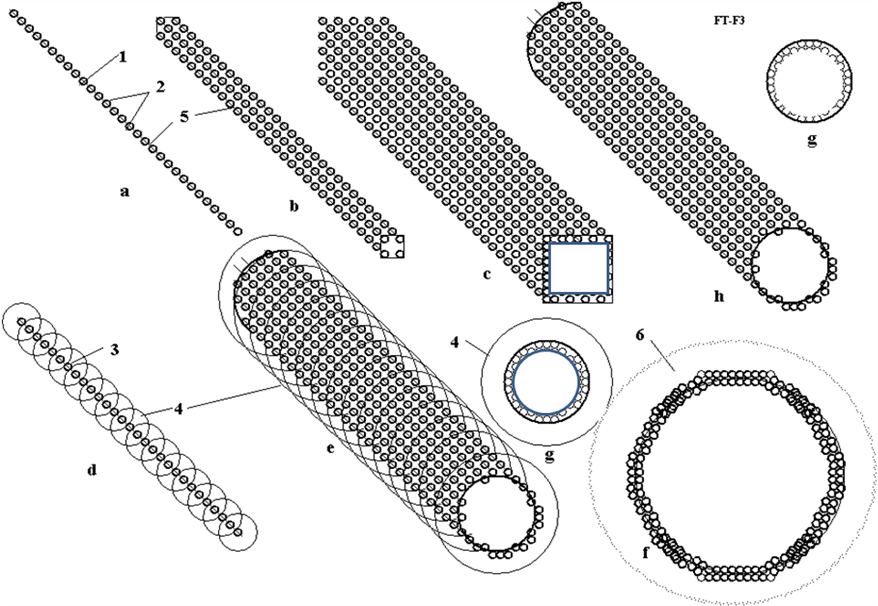
Fig. 3. Design of AB-matter from nucleons (neutrons, protons, etc.) and electrons (a) linear one string (monofilament) (fiber, whisker, filament, thread, needle); (b) ingot from four nuclear monofilaments; (c) multi-ingot from nuclear monofilament; (d) string made from protons and neutrons with electrons rotated around monofilament; (e) single wall femto tube (SWFT) fiber with rotated electrons; (f) cross-section of multi wall femto tube (MWFT) string; (g) cross-section of tube; (h) single wall femto tube (SWFT) string with electrons inserted into AB-matter. Notations: 1-nuclear string; 2-nucleons (neutrons, protons, etc.). 3-protons; 4-orbit of electrons; 5-nucleons; 6-cloud of electrons around tube.
The main difference between the AB-matter and conventional matter is a strict order of location the proton and neutrons (for example: proton-neutron-proton-neutron) in line (string) or in the super thin (in one nucleon) plate (nuclear graphene). That gives the strong tensile stress (electrostatic repulse force) which does not allow the nucleons to mix in messy clump (ball). This force is less than a nuclear force if the AB-matter has a form where the most protons are located far from one another, where the nuclear force from the far protons is absent. That is in line, net and plate (Fig. 1a, b, d), but that may be absent in the solid beam, rod (Fig. 3c, d) if their cross-section area contains a lot of nucleons. The other problem: compensation of the positive charges is solved by rotating electrons around the AB string, rod, tube, net (grid) or an electron cloud near the plate [1] or the electron locates near nucleons.
-
Using the AB-matter
The simplest use of AB-matter is strengthening and reinforcing conventional material by AB-matter fiber. As is shown in the `Computation' section [1], AB-matter fiber is stronger (has a gigantic ultimate tensile stress) than conventional material by a factor of millions of times, can endure millions degrees of temperature, and does not accept any attacking chemical reactions. We can insert (for example, by casting around the reinforcement) AB-matter fiber (or net) into steel, aluminum, plastic and the resultant matrix of conventional material increases in strength by thousands of times--if precautions are taken that the reinforcement stays put! Because of the extreme strength disparity design tricks must be used to assure that the fibers stay `rooted'. The matrix form of conventional artificial fiber reinforcement is used widely in current technology. This increases the tensile stress resistance of the reinforced matrix matter by typically 2-4 times. Engineers dream about a nanotube reinforcement of conventional matrix materials which might increase the tensile stress by 10-20 times, but nanotubes are very expensive and researchers cannot decrease its cost to acceptable values yet despite years of effort. Another way is to use a construct of AB-matter as a continuous film or net (Fig. 2b, d) or as the AB-needles (Fig. 2) [3].
These forms of AB-matter have such miraculous properties as invisibility, superconductivity, zero friction, etc. The ultimate in camouflage, installations of a veritable invisible world can be built from certain forms of AB-matter with the possibility of being also interpenetable, literally allowing ghost-like passage through an apparently solid wall. Or the AB-matter net (of different construction) can be designed as an impenetrable wall that even hugely destructive weapons cannot penetrate.
The AB-matter film and net may be used for energy storage which can store up huge energy intensities and used also as rocket engines with gigantic impulse or weapon or absolute armor (see computation and application sections in [1-3]). Note that in the case of absolute armor, safeguards must be in place against buffering sudden accelerations; g-force shocks can kill even though nothing penetrates the armor!
The AB-matter net (which can be designed to be gas-impermeable) may be used for inflatable construction of such strength and lightness as to be able to suspend the weight of a city over a vast span the width of a sea. AB-matter may also be used for cubic or tower solid construction as it is shown in Fig. 3. Detailed computation of properties of the AB-matter is in [1-3]. Our purpose is to show that the curtain forms of AB-matter will be stable and may be produced.
2. About stability of the nuclear ab-matter
-
Short Information About Atom and Nuclei
Conventional matter consists of atoms and molecules. Molecules are collection of atoms. The atom contains a nucleus with proton(s) and usually neutrons (except for Hydrogen-1) and electrons revolve around this nucleus. Every particle may be characterized by parameters as mass, charge, spin, electric dipole, magnetic moment, etc. There are four forces active between particles: strong interaction, weak interaction, electromagnetic charge (Coulomb) force and gravitational force. The nuclear force dominates at distances up to 1.5 ¤ 2 fm (femto, 1 fm = 10-15 m). They are hundreds of times more powerful than the charge (Coulomb) force and million-millions of times more than gravitational force. Charge (Coulomb) force is effective at distances over 2 fm. Gravitational force is significant near and into big masses (astronomical objects such as planets, stars, white dwarfs, neutron stars and black holes). Strong force is so overwhelmingly powerful that it forces together the positively charged protons, which would repel one from the other and fly apart without it. The strong force is key to the relationship between protons and neutrons. Electric force can keep electrons near nuclei. Scientists conventionally take into attention only the strong force when they consider the nuclear and near nuclear size range, and the other forces on that scale are negligible by comparison for most purposes.
Strong nuclear forces are anisotropic (non-spherical, force distribution not the same in all directions equally), which means that they depend on the relative orientation of the nucleus. The proton has a magnetic moment which produces the magnetic force. This force orients the proton in magnetic field and helps to keep the form of AB-matter.
Typical nuclear energy (force) is presented in Fig. 4. The nuclear and electric forces can be attractive and repulsive. When it is positive the nuclear force repels the other atomic particles (protons, neutrons). When nuclear energy is negative, it attracts them up to a distance of about 2 fm. The value r0 is usually taken as radius of nucleus.
Fig. 4 Typical nuclear force of nucleus. When nucleon is at distance less than 1.8 fm, it is attracted to nucleus.
When nucleon is very close, it is repulsed from nucleus [11].
-
Law (Necessary Conditions) of Stability the AB-matter
The necessary conditions (prerequisite law) of stability the AB-matter are as following:
1) The number of protons must be less approximately 90 into a local sphere of radius 3 fm in any point of AB-matter;
2) The number of nucleons must be less approximately 240 into a local sphere of radius 3 fm in any point of AB-matter;
3) The AB-matter contains minimum two protons.
4) Any neutron has minimum one contact with proton.
That law follows from relation between attractive nuclear and repulsive electrostatic forces into nucleus. The nuclear force is short distance force (2 fm), the electrostatic force is long distance force. When number of protons is more than 92 (in lamb), the repulsive electrostatic force may become more than nuclear force and electrostatic force may destroy the AB-matter. That law means the number of nucleons in any perpendicular cross-section area AB-matter design of Fig. 3 must be less than 37.
The press strong possibilities of the AB-matters are very large because AB-needles has the surprising property discovered by author - keep the huge press force in any length of AB-needle (transfer the pressure to any long distance). That properties are described in [3] and shortly in below.
3. ab-needles
The most important design of AB-matter is connection of nucleons in string (Fig. 5a, b, c). That may be only protons pppp.... (Fig. 5a), proton-neutron-proton-neutron-.... (pnpn....)(Fig. 5b), proton-neutron-neutron-proton-neutron-neutron-.... (pnnpnn....)(Fig. 5c). The ends of AB-string contains the protons. The electrostatic repulse force of these end protons is not balanced and creates the strong repulsive force 3 (Fig. 5c,d,e) which stretches the AB-string. That helps to keep the string form and other forms (plate, tube, beam, shaft, rod, etc.) of AB-matter presented in Figs. 3, 5. This is very important properties. This property does not have the conventional molecular matter, because the conventional matter contains the neutral molecules. The charges of ions in conventional matter locate far from one another and repulsive force is small. That property discovered by author gives the AB-string the amusing feature: an independence of the safety press stress from length of the nuclear string. Remand: the safety press force of long conventional matter strong depends on length of wire, beam, shaft, etc. According to the Euler's law the safety compressive force in the ordinary matter is inversely proportional to the square of the length of the rod. If the length of rod is more than the safety length, the construction losses the stability (one is bending). You cannot push the car a thread or thin wire having one km length. They bend. The AB thin string can pass the compressive force for any length of string. That is why it is named the AB-needle. AB-needle allows penetrating into any conventional matter, into the interior of Earth, planets, Sun. They allow making the interplanetary trips and investigations of planet from Earth.
Fig. 5 Connection of nucleons in string (needle) (Fig. 2a, b, c) and film, plate (Fig.5d, e) and Coulomb (electrostatic, repulse) force. Notations: 1-protons, 2-neutrons, 3-repulse (Coulomb) force from protons.
4. Theory of AB-needles
A) Estimation of magnetic force the nucleons.
Proton and neutron have the magnetic momentum pm. That means they are magnets. Magnets have North and Source poles and have ability connecting one to other in line. Let us to calculate this force and compare it with the nuclear and electrostatic forces.
The magnetic momentum pm (J/T) is creating the circle currency I (fig. 6). It is
pm = Is , (1)
where I is electric currency, A; s = ?r2 is a circle area of electric currency, m2; r is radius of circle, m.
Magnetic momentum of proton, neutron are known. The radius of the proton charge is also measured. In any case it is less than the radius of particles. From (1) we calculate the minimal electric currency of nucleon
I = pm/s . (2)
The magnetic intensity H in point "A" located in circle axis OA (fig.5) is
. (3)
For b = 0 the magnetic intensity in circle center is
(4)
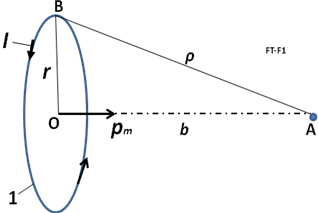
Fig.6. For theory of the magnetic intensity in an axis of the circle currency having the magnetic momentum pm . Notations: A is point where we measure the magnetic intensity H; 1 - current circle is creating the electric charge: r is radius, I is electric currency, pm is magnetic momentum; b is distance of line OA; ? is distance AB.
The charge of proton is e = +1.6.10-19, C. That allows to calculate the number of charge revolutions n (1/s) and speed of charge V (m/s):
(5)
where V must be less than the light speed c = 3.108 m/s.
If we know the magnetic intensity, we can estimate the attractive force F (N) of opposed pole same (closed) magnet
(6)
where ?o - 4?.10-7 is magnetic constant (permeability) ( N/A2). F0 is force (N) in center of the currence circle.
The computation shows: the magnetic forces have the significantly value.For example, the proton has pm = 1.41в10-26 J/T, the radius r = 0.8775в10-15 m. From (6) we get F0 = 16.9 N. This force is closed to the nuclear + electric forces. The spherical distribution (as dot lines) of these forces along the radius are shown in fig. 7. As the result the attractive forces along the magnetic momentum axis is considerable more than in perpendicular axis. The force body has a form of rotated oval or ellipsoid. In result the protons and neutrons may be orientated in outer magnetic field and connected into AB-needle or filament as shown in fig.7d.
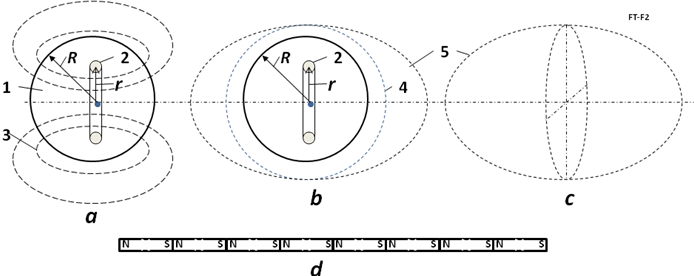
Fig.7. For computation of the magnetic force from the magnetic momentum of a nucleon (proton or neutron). Notations: a - nucleon: 1 - nucleon having radius R, 2 -electric currency ring having radius r, 3 - magnetic lines from the magnetic momentum. b - magnitudes of forces near nucleon: 4 - nuclear and electrostatic forces, 5 - magnetic force. Magnitudes equal a distance from the center to the dot line. c - form of forces in isometric view. Form is closed to a rotated oval or rotated ellipsoid. d - is AB needle from nucleons connected in line as magnets.
The magnetic forces of nucleons may be significantly increased when they connected one to other (fig.8a). In this case they work as solenoid having the summary electric currency and an inverse linear relationship from a length of solenoid d (not inverse relationship of the third order as in (4)-(3)).
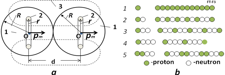
Fig.8. Left: Two connected nucleus work as solenoid. Their magnetic force is increases. 3 is common magnetic lines. Right: AB-needles: Notations: 1 - AB-needle from protons (pppp...); 2 - AB-needle from one proton + one neutron (pnpn...); 3 - AB-needle from one proton + two neutrons (pnnpnn...); 4 - AB-needle from one proton + three neutron (pnnnpnnn...), 5 - AB-needle from two protons + two neutrons (ppnnppnn...)(ends have one proton).
The magnetic intensity (H) and force between two nucleons as solenoid may be computed the equations:
(7)
where I1 is circle electric currency in the first nucleon (A), I2 is circle electric currency in the second nucleon (A); d is distance between circles (m), d - 2R; Fd is force, N; s = ?r2 is a circle area of the electric currency, m2. If solenoid row have n same nucleons, the summary magnetic intensity of long solenoid changes as:
. (8)
The AB-needles can have the different structures. Some of them are sown in fig. 8b. For example: The first AB-needle (fig.8b-1) contains only protons (pppp...). The second (fig. 8b-2) - contains the proton-neutron (pnpn...). The third (fig. 8b-3) - contains proton and two neutrons (pnnpnn...). The fourth (fig.8b-4)- contains proton + three neutrons (pnnnpnnn...). The fifth (fig.8b - 5) - contains two protons + two neutrons (ppnnppnn...). I think for stability AB-needle (include many row needles about every neutrons must be proton because some theory propose the proton and neutron are exchanging the charge.
The repulse electrostatic force between two protons is
(9)
where k = 9в109 N.m2/C2 is electrostatic constant; d is distance between two protons, m. If row (thread) contains only protons the maximal summary electrostatic force is
(10)
The average nuclear force FN (N) equals approximately
(11)
where E is avarage nuclear connection (binding) energy (J), l is average distance of the active force (m).
For the hydrogen nucleus 2H (proton + neutron) the nuclear binding energy equals 1 MeV [12, p.547] . That means E = 1,6в10-13 J. The active distance of the nuclear force is about l = 10-15 m.
Substitute it into equation (11) we get the average nuclear force
FN = 160 N. (12)
Numerical estimation.
-
Let us estimate the forces between proton - proton. It is known the radius R (m) of nucleon approximately equals
(11)
where A is number of nucleons into nucleus. In our case A = 1 and
m for all nucleons (proton and neutron). The radius of positive charge into proton is known and equal r = 0.8775в10-15 m. The magnetic momentum of proton is pm = 1.41в10-26 J/T.
Using the equation above we can compute magnetic force and next parameters of solenoid from couple neutrons:
(12)
(13)
. (14)
For solenoid having two protons we get:
(15)
Note: the attractive nuclear force FN =160 N (12) is significantly more than repulsive electrostatic force Fe = - 40N.
2. Let us estimate the solenoid magnetic force in couple proton + neutron. The magnetic momentum of neutron is pm = - 0.966в10-26 J/T. Sign minus means the vector of magnetic moment and vector of mechanical momentum (spin) is opposed. It is not important for us because we can turn the vector of the magnetic force in a need direction by an outer magnetic field.
Let us take the radius of neutron equals the radius of proton R = 1.2в10-15 m and radius
of charge into neutron equal to radius of charge of proton r = 0.8775в10-15 m.
Using the equation above we can compute the next values and force in neutron:
(16)
(17)
. (18)
For solenoid having two protons we get:
(19)
The attractive nuclear force FN =160 N (12).
3. Let us estimate the solenoid magnetic force in couple neutron + neutron. The magnetic momentum of neutron is pm = - 0.966в10-26 J/T. Sign minus means the vector of magnetic moment and vector of mechanical momentum (spin). Let us take the radius of neutron equals the radius of proton R = 1.2в10-15 m and radius of charge into neutron equal to radius of charge of proton r = 0.8775в10-15 m.
Using the equation above we can compute the next values and force in neutron:
(20)
(21)
. (22)
For solenoid having two protons we get:
(23)
The attractive nuclear force FN =160 N (12).
This computations show: the magnetic forces of protons and neutrons allow to design from them the long AB-treads if we connect them by the corresponding magnetic poles. We can make their need orientation by the outer magnetic field. If AB-thread contains the correct located protons one became the springy AB-needle.
5. SOME APPLICATION of AB-needles
Some constructions from AB-string are shown in Fig.9.
Fig. 9. Some construction from AB-string. Notations: a - vertical string (AB-needle). The big lift (support) force 4 does not depend from length; b - lifting the load to any altitude. 5 - spool of AB-string; c - stability of AB-string; d - ring 6 from AB-string; e - bridge (long arm) from AB-string; f - research of the Earth crust interior: 8 - installation (spool of AB-needle), 9 - AB-needle (string, cable).
AB-needles may be illustrated by a children long inflatable air-balloon (Fig. 10a). This press force also does not depend on length of balloon. The force is transferred by compressed air. This idea was used by author in designing the inflatable space tower [5].
The tension Fp activates along all lengths of AB-needle and does not allow to curl the AB-string into the lamb - conventional nucleus. This tension works when there are no other closed protons with a side of the string. When AB-needle is created, the outside protons cannot joint to AB-needle because the protons repel each other.
The proton and neutron have the magnetic dipole moments. Magnetic dipole moment of proton equals +1.41"10-26 J/T, and magnetic dipole moment of neutron equals -0.966"10-26 J/T. They are small magnets having magnetic force some newtons. That also allows creating the stable AB-needles, to arrange them in a certain position and order.
The AB-needle can also keep the maximal side force F2 - 0.5F1 (Fig. 10b). That allows accelerating anybody (for example space ship) in side direction, to produce an elastic design (for example, air bridge, storage of mechanical energy, long arm (hand), etc.). AB-matter designs do not have the drawbacks of the ordinary matter as fatigue, residual strain and the susceptibility to the external environment.
Fig. 10. Applications of AB-needles. Notations: a - conventional children inflatable long tube illustrated the capability to accept the pressure in end of tube (F - force); b - illustration of AB-needle to lift the load, accepts the vertical and horizontal forces (F1, F2 = 0.5F1); c - AB-needles as the over GSO Space Elevator; d - AB-needles as space ship and the investigator of the planet interior (for example Moon); e - the building suspended at high altitude by AB - needles, f - the investigation of interior of building, men, etc. by AB-needles. 1- conventional children inflatable long tube (air balloon); 2 - AB-needles; 3 - reel of AB-needles; 4 - the guides of AB-needles; 5 - Earth; 6 - Geosynchronous orbit; 7 - space ship; 9 - building; 10 - AB-needle; 11 - the guides of AB-needles; 12 - devices (TV-camera, capture grid, weapon, etc.); 13 - elevator.
One meter of AB-needle has line having n = 5.7.10-14 nucleons with mass m = 1.67. 10-27 kg. Total mass of one meter AB-needle equals only 10-12 kg/m.
M1 = nm = 5.7.10-14 в1.67.10-27 = 10-12 kg/m.
One million kilometers of AB-needle weights only 10-3 kg/Mm. For transferring the large force we can take the thin cable from AB-needles.
-
Summary
Four above necessary conditions, repulsive force of protons and magnetic force of nucleons can make the stability of AB-matter.
6. production of ab-needles
The charged particles interact with electric and magnetic fields. The magnetic moment interacts with magnetic field. That allows designing the technologies for production of artificial AB-matter. Some offered technologies were described in [1]. Here the author offers some new technologies.
The possible particles are shown in Table 1.
table 1. charge, impulse and magnetic moments of some nucleus
|
Z |
Nucleus |
Charge |
Mass |
Impulse |
Magnetic* |
|
0 |
n |
0 |
1 |
1/2 |
-1.9125 |
|
1 |
p |
1 |
1 |
1/2 |
2.7828 |
|
1 |
2H = D |
1 |
2 |
1 |
0.8565 |
|
2 |
3He |
2 |
3 |
1/2 |
-2.121 |
|
2 |
4He |
2 |
4 |
0 |
0 |
|
3 |
6Li |
3 |
6 |
1 |
0.821 |
|
3 |
7Li |
3 |
7 |
3/2 |
3.2332 |
*Nuclear magnetron ЅN = 5.051"10Ђ27 J/T. Sign "-"shows: magnetic moment is opposite the impulse moment.
-
Notes About Possible Form AB-needles
The possible form of AB-needles is shown in Fig. 11.
The first form marked 1 (pppp...) contains only line of protons. This form is cheapest and has maximum pressure strength. But it is unknown whether this form is possible or not. It is known the single hydrogen and single proton are stable. In other side the fusion of two single hydrogen nuclei 1H (protons) produces deuterium 2H= D (pn) releasing a positron and a neutrino as one proton changes into a neutron:
1H + 1H ? 2H + e+ + ?e + 0.42 MeV (24)
The fusion reaction released in this step produces energy up to 0.42 MeV. The most of this energy is taken away by neutrino.
The positron immediately annihilates with an electron, and their mass energy is carried off by two gamma ray photos:
e+ + e-- ? 2? + 1.02 MeV . (25)
But most nucleuses have a lot of protons and they do not rely on the reaction (24). The AB-needle also has a lot of protons. If reaction (24) is released, the form 1 transfers in form 2 (Fig. 11) and the process produces a lot of nuclear energy. The ionized conventional hydrogen 1H may be used for production of AB-matter. I remain: the Universe is composed of about 80% hydrogen. As a result we will have the AB-needle in form npnp... .
The second form of AB-needle is pnpn... marked 2 (Fig. 11). This form may be produced directly from deuterium D oriented by magnetic field along axis of AB-needles. The third form of the double AB-needles marked 3 (Fig. 10) may be also produced directly from deuterium D oriented by magnetic field perpendicular of axis of AB-needles. The forth form of four-needles marked 4 (Fig. 11) may be produced directly from helium 4He oriented by magnetic field perpendicular of axis of AB-needles.
Fig.11 Types of AB-needles. Notations: a - Nucleus: black is p, white is n; b - AB-needles (side view); c - AB-needles in isometrical view; d - increasing the internal tensile stress by the double protons (5) located in the end of single AB-needle from protons (for increasing the tensile stress); 1- protons (p). Single AB-needles from proton; 2 - deuterium 2H = D (pn). Single AB-needles from deuterium; 3 - deuterium 2H (pn). Double AB-needles from deuterium; 4 - helium 4He. 4 - square AB-needles from helium. 5 - double protons in end of single AB-needle.
-
Installations for Production AB-needles
1) The First Method: Toroid Method:
One of installation for production of AB-needles is shown in Fig. 12. The installation has a vacuum topoid 1 and particles gun 4 which injects charged particles into toroid. The perpendicular (to fig.) magnetic lines 2 penetrate the toroid. As a result the charged particles 3 move in circles inside the toroid. This electric current of particles produces the magnetic field 5 (pinch-affect). This field pulls the particles in a cord and helps to keep them into the toroid ring.
Fig. 12 Toroid producer of AB-needles (AB-matter). Notations: 1 - vacuum toroid; 2 - perpendicular (to sketch) magnetic lines; 3 - particles; 4 - particles gun; 5 - round magnetic lines from motion charged particles; 6 - electric accelerator; 7 - electric focuser; 8 - AB - needles; 9 - magnetic field keeping the AB-needles; 10 - electric focuser; 11 - electric accelerator.
The producing AB-needles 8 locate inside the toroid ring and are kept by special local magnetic field 9 in position along the circle axis of the toroid ring. That means the moving particles can connect to AB-needles only to end nucleus when they collide the forward end of AB-needle and their energy is sufficient to overcome the Coulomb repulsion. The toroid ring has the accelerators 6, 11 and focusers 7, 10 of particles. Their electric fields collect the scattered charged particles back to toroid axis.
Probability of hitting in the front end of the AB-needles is small. But the charged particles rotate into toroid a lot (millions) of times and join to end of AB-needles. Note they can connect only to end of AB-needle. Their perpendicular speed to the toroid circle axis is not enough to overcome the nuclear repulsion force.
Author wrote only the principal scheme (schematic diagram) of the AB-needle producing. The developing of this method may request a big research and work.
2) The Second Method: Method Particles Traps:
That is shown in Fig. 13. That is closed to method described in [1-3]. Feature is the net of traps 8 (Fig. 13a and 13b). They catch the particles and direct them to end of creating AB-needles. Advantage is high efficiency of production AB-matter (every charged particle will be used, small of energy consumption). Lack is the request of a special form of AB-matter (see 8 in Fig. 13b). That method may be useful when we have enough AB-matter.
Fig. 13. Method particle traps for production of the AB-needles. Notations: a - device; b - particle traps; 1 - vacuum cell; 2- charged particles; 3 - magnetic lines; 4 - electric issue for the acceleration nets; 5 - plasma from particles; 6 - flow of electrons; 7 - AB-needles; 8 - trap made from AB-matter for the charged particles (p, 2H, 4He, etc.); 9 - cell for cover the AB-needles by electrons.
3) The Third Method: Method Standing Waves:
The current special mirrors [4, Ch.12] and lasers allow to create the net of electromagnetic traps for AB-matter producer (Fig. 14) from the monochromatic polarized electromagnetic standing waves (Fig. 14a, b). That net may partially change the net of AB-matter traps of the Fig. 14b and increase the efficiency. This method may be useful for AB-matter producer in [1-3].
Fig. 14. Net of electromagnetic traps for AB-matter producer. Notations: a - forward view; b - the monochromatic polarized electromagnetic standing waves (electrostatic part, side view); c - particles storage and accelerator; 1 - net from the perpendicular monochromatic polarized electromagnetic standing waves; 2 - the electromagnetic monochromatic polarized standing wave; 3 - electric accelerator of particles; 4 - particles.
The threads from AB-matter are stronger by millions of times than normal materials. They can be inserted as reinforcements, into conventional materials, which serve as a matrix, and are thus strengthened by thousands of times (see computation section in [1]).
The offered AB-producers can be used for producing the new NANO-matters. Now the scientist offers to produce nano-matters by nano-robots. I think that is a very difficult way. The nano-robot must have the devices for searching, recognizing, catching the flying molecules, deliver them in given place, and connect to other selected molecules. That means the nano-robot must have a million molecules. It is difficult to get an elephant to catch the flies and glue them from the device. This productivity will be very low. The production of AB-matter may be easy.
Also we can ionize the molecules (create the charged particles!) and apply the modified offered methods for design and production of the nano-matters.
7. discussion
The humanity will make a gigantic jump in technology when one will produce AB-matter. We consider unconventional application of AB-matter.
-
Super Micro-World from AB-Matter: An Amusing Thought-Experiment
AB-matter may have 1015 ¤ 1043 times more particles in a given volume than a single atom. A human being, man is made from conventional matter, contains about 5в1026 molecules. That means that `femto-beings' of equal complexity from AB-matter (having same number of components) could be located in the volume of one microbe having size 10 ? = 10Ђ5 m. It is difficult to make the nano-robot (one is large for Nano World). But the smart small femto-robot is suitable for Nano World. In future the people could make the artificial intelligent super micro F-beings which can withstand a huge temperature, acceleration of electric field, travel to other stars, other galactic, live in stars and travel through black holes to other universes and times.
-
Stability of AB-matter
Readers usually ask: the connection (proton to proton) gives a new element when, after 92 protons, this element is unstable?
Answer: That depends entirely on the type of connection. If we conventionally join the carbon atom to another carbon atom a lot of times, we then get the conventional piece of a coal. If we join the carbon atom to another carbon atom by the indicated special forms, we then get the very strong single-wall nanotubes, graphene nano-ribbon (super-thin film), armchair, zigzag, chiral, fullerite, torus, nanobud and other forms of nano-materials. That outcome becomes possible because the atomic force (van der Waals force, named for the Dutch physicist Johannes Diderik van der Waals, 1837-1923, etc.) is non-spherical and active in the short (one molecule) distance. The nucleon nuclear force is also non-spherical and they may also be active about the one nucleon diameter distance (Fig. 1). Moreover, the nucleus are tensile electrostatic force which allows designing the long linear structures. Moreover, the proton and neutron are the small magnets. The magnets (and nucleus) connect one to other specific side. That means we may also produce with them the strings, tubes, films, nets and other geometrical constructions.
The further studies are shown that AB-matter will be stable if:
1) The any sphere having radius R - 6в10-15 m in any point of structure Figs. 1- 4 must contain no more than 238 nucleons (about 92 of them must be protons). That means any perpendicular cross-section area of the solid rod, beam and so on of AB-structure (for example figs. 1b,c,g) must contain no more than about 36 nucleons in any circle with R - 6в10-15 m.
2) AB-matter must contain the proton in a certain order because the electrostatic repel forces of them give the stability of the given structure.
3) The magnetic force of protons and neutrons also allows giving the different forms of AB-matter.
8. conclusion
The author offers a design for a new form of nuclear matter from nucleons (neutrons, protons), electrons, and other nuclear particles. He also suggests the necessary conditions of stability of AB-matter. He shows that the new AB-matter has most extraordinary properties (for example, (in varying circumstances) remarkable tensile strength, stiffness, hardness, critical temperature, superconductivity, super-transparency, ghostlike ability to pass through matter, zero friction, etc.), which are millions of times better than corresponded properties of conventional molecular matter. He shows (in [2]) how to design aircraft, ships, transportation, thermonuclear reactors, and constructions, and so on from this new nuclear matter. These vehicles will have correspondingly amazing possibilities (invisibility, passing through any wall and amour, protection from nuclear bombs and any radiation, etc).
People may think this is fantasy. But fifteen years ago most people and many scientists thought nanotechnology is fantasy. Now many groups and industrial labs, even startups, spend hundreds of millions of dollars for development of nanotechnological-range products (precise chemistry, patterned atoms, catalysts, metamaterials, etc) and we have nanotubes (a new material which does not exist in Nature!) and other achievements beginning to come out of the pipeline in prospect. Nanotubes are stronger than steel by a ten times--surely an amazement to a 19th century observer if he could behold them.
Nanotechnology, in near term prospect, operates with objects (molecules and atoms) having the size in nanometer (10-9 m). The author here outlines perhaps more distant operations with objects (nuclei) having size in the femtometer range, (10-15 m, millions of times smaller than the nanometer scale). The name of this new technology is femtotechnology.
I want to explain the main thrust of this by analogy. Assume some thousands of years ago we live in a great river valley where there are no stones for building and only poor timber. In nature we notice that there are many types of clay (nuclei of atom--types of element). One man offers to people to make from clay bricks (AB-Matter) and build from these bricks a fantastic array of desirable structures too complex to make from naturally occurring mounds of mud. The bricks enable by increased precision and strength things impossible before. A new level of human civilization begins.
The author calls upon scientists and the technical community to research and develop femtotechnology [10]. We can reach progress more quickly than in the further prospects of nanotechnology in this field, because we have fewer (only 3) initial components (proton, neutron, electron) and interaction between them is well-known (3 main forces: strong, weak, electrostatic). The different conventional atoms number about 100, most common molecules are tens of thousands and interactions between them are very complex (e.g. Van der Waals force).
What time horizon might we face in this quest? The physicist Richard Feynman offered his idea to design artificial matter from atoms and molecules at an American Physical Society meeting at Caltech on December 29, 1959. But only in the last 15 years we have initial progress in nanotechnology. On the other hand, progress is becoming swifter as more and better tools become common and as the technical community grows.
Now we are in the position of trying to progress from the ancient `telega' haywagon of rural Russia (in analogy, conventional matter composites) to a `luxury sport coupe' (advanced tailored nanomaterials). The author suggests we have little to lose and literal worlds to gain by simultaneously researching how to leap from `telega' to `hypersonic space plane'. (Femotech materials and technologies, enabling all the wonders outlined here) [1 - 10].
acknowledgement
The author wishes to acknowledge Joseph Friedlander (of Shave Shomron, Israel) for correcting the English and offering useful advices and suggestions.
references
(The reader may find some of these articles at the web storages: http://www.scribd.com , http://arxiv.org , http://vixra.org, http://aiaa.org , search "Bolonkin" and in the author's books: "Non-Rocket Space Launch and Flight", Elsevier, London, 2005, 488 pages; "New Concepts, Ideas, Innovations in Aerospace, Technology and Human Science", NOVA, 2006, 502 pages and "Macro-Projects: Environment and Technology", NOVA 2007, 536 pages; "New Technologies and Revolutionary Projects", Scribd, 2008, 324 pgs; Innovations and New Technologies. Scribd, 2013. 309 pgs. 8 Mb.).
-
Bolonkin A.A., Femtotechnology. Nuclear AB-Matter with Fantastic Properties, American Journal of Engineering and Applied Sciences. 2 (2), 2009, p.501-514. Presented as paper AIAA-2009-4620 to 7th Annual International Energy Convention Conference, 2-5 August 2009, Denver, CO, USA. [On line]: http://www.scribd.com/doc/24045154. http://viXra.org/abs/1309.0201 .
-
Bolonkin A.A., Femtotechnology: Design of the Strongest AB-Matter for Aerospace. Presented as paper AIAA-2009-4620 to 45 Joint Propulsion Conference, 2-5 August, 2009, Denver CO, USA. See also closed paper AIAA-2010-1556 in 48 Aerospace Meeting, New Horizons, 4 - 7 January, 2010, Orlando, FL, USA. http://www.archive.org/details/FemtotechnologyDesignOfTheStrongestAb-matterForAerospace . Published in "Journal of Aerospace Engineering", Oct. 2010, Vol. 23, No. 4, pp.281-292. http://www.archive.org/details/FemtotechnologyDesignOfTheStrongestAb-matterForAerospace http://www.scribd.com/doc/57369206/Femtotechnology-Design-of-the-Strongest-AB-Matter-for-Aerospace
-
Bolonkin A.A., AB-needles: Fantastic Properties and Application in Energy. International Journal of Energy Engineering (IJEE), December, 2013.
-
Bolonkin A.A., Converting of Matter to Nuclear Energy by AB-Generator. American Journal of Engineering and Applied Sciences. 2 (4), 2009, p.683-693. [on line] http://www.scribd.com/doc/24048466. http://viXra.org/abs/1309.0200
-
Bolonkin A.A., "Non-Rocket Space Launch and Flight", Elsevier, 2005, 488 pgs. ISBN-13: 978-0-08044-731- 5, ISBN-10: 0-080-44731-7 . http://www.archive.org/details/Non-rocketSpaceLaunchAndFlight, http://www.scribd.com/doc/24056182.
-
Bolonkin A.A., "New Concepts, Ideas, Innovations in Aerospace, Technology and the Human Sciences", NOVA, 2006, 510 pgs. ISBN-13:978-1-60021-787-6.http://www.scribd.com/doc/24057071 , http://www.archive.org/details/NewConceptsIfeasAndInnovationsInAerospaceTechnologyAndHumanSciences, http://viXra.org/abs/1309.0193,
-
Bolonkin A.A., Cathcart R.B., "Macro-Projects: Environments and Technologies", NOVA, 2007, 536 pgs. ISBN 978-1-60456-998-8. http://www.scribd.com/doc/24057930 . http://viXra.org/abs/1309.0192 , http://www.archive.org/details/Macro-projectsEnvironmentsAndTechnologies
-
Bolonkin A.A., "New Technologies and Revolutionary Projects", Scribd, 2008, 324 pgs, http://www.scribd.com/doc/32744477, http://www.archive.org/details/NewTechnologiesAndRevolutionaryProjects.
-
Bolonkin A.A., LIFE. SCIENCE. FUTURE (Biography notes, researches and innovations). Lambert, 2010, 208 pgs. 16 Mb. ISBN: 978-3-8473-0839-3 . http://www.scribd.com/doc/48229884, http://www.archive.org/details/Life.Science.Future.biographyNotesResearchesAndInnovations, http://viXra.org/abs/1309.0205 , http://www.lulu.com, search "Bolonkin".
-
Bolonkin A.A., Femtotechnologies and Revolutionary Projects. Lambert, USA, 2011. 538 p. 16 Mb. ISBN: 978-3-8473-0839-0. http://www.scribd.com/doc/75519828/, ISBN 078-1-105-64111-4; http://viXra.org/abs/1309.0191, http://www.archive.org/details/FemtotechnologiesAndRevolutionaryProjects .
-
http://www.physicum.narod,ru, Vol. 5., p.670.
-
AIR Physics Desk Reference, Third Edition, p. 547.
13 November 2013.
Chapter 8
Universe (Part 3 and summary Parts 1 - 2).
Relations between Charge, Time,Matter, Volume, Distance, and Energy .
Summary
In Universe (Part 1)[1] author has developed a theory which allows derivation of the unknown relations between the main parameters (energy, time, volume, matter) in the Universe. In given part 3 he added charge as main parameter in this theory. He finds also the quantum (minimal values) of energy, time, volume and matter and he applied these quantum for estimations of quantum volatility and the estimation of some values of our Universe and received both well-known and new unknown relations.
Author offers possibly valid relations between charge, time, matter, volume, distance, and energy. The net picture derived is that in the Universe exists ONLY one substance - ENERGY. Charge, time, matter, volume, fields are evidence of this energy and they can be transformed one to other. Author gives the equations which allow to calculate these transformation like the famous formula E = mc2. Some assumptions about the structure of the Universe follow from these relations.
Most offered equations give results close to approximately known data of Universe, the others allow checking up by experiment.
Key words: Universe, time, matter, volume, distance, energy; limits of specific density of energy, matter, pressure, temperature, intensity of fields; collapse of space and time into point.
Introduction
In the theoretical physic the next fundamental constants presented in Table 1 are important .
Table 1: Fundamental physical constants
|
Constant |
Symbol |
Dimension |
Value in SI units with uncertainties |
|
Speed of light in vacuum |
c |
L T?--1 |
2.99792458в108 m s--1 |
|
Gravitational constant |
G |
L3 M--1 T?--2 |
6.67384(80)в10--11 m3 kg--1 s--2 |
|
Reduced Planck constant |
? = h/2? |
L2 M T?--1 |
1.054571726(47)в10--34 J s |
|
Coulomb constant |
(4??0)--1 |
L3 M T?--2 Q--2 |
8.9875517873681764в10^9 kg m3 s--2 C--2(exact by definitions of ampere and meter) |
|
Boltzmann constant |
kB |
L2 M T?--2 ?--1 |
1.3806488(13)в10--23 J/K |
Where are: L = length, M = mass, T = time, Q = electric charge, ? = temperature.
If we take these constants as base units, we get the Planks units:
Table 2: Base Planck units
|
Name |
Dimension |
Expression |
Value (SI units) |
|
Planck length
|
Length (L) |
|
1.616?199(97) в 10--35 m |
|
Planck mass |
Mass (M) |
|
2.176?51(13) в 10--8 kg |
|
Planck time |
Time (T) |
|
5.391?06(32) в 10--44 s |
|
Planck Charge |
Electric charge (Q) |
|
1.875?545?956(41) в 10--18 C |
|
Planck temperature |
Temperature (?) |
|
1.416?833(85) в 1032 K |
From data Table 2 we can receive the derived Planck units (Table 3).
Table 3: Derived Planck units
|
Name |
Dimension |
Expression |
Approximate SI equivalent |
|
Planck area |
Area (L2) |
|
2.61223 в 10--70 m2 |
|
Planck volume |
Volume (L3) |
|
4.22419 в 10--105 m3 |
|
Planck momentum |
Momentum (LMT--1) |
|
6.52485 kg m/s |
|
Planck energy |
Energy (L2MT--2) |
|
1.9561 в 109 J |
|
Plank force |
Force (LMT--2) |
|
1.21027 в 1044 N |
|
|
Power (L2MT--3) |
|
3.62831 в 1052 W |
|
Planck density |
Density (L--3M) |
|
5.15500 в 1096 kg/m3 |
|
Planck energy density |
Energy density (L--1MT-2) |
|
4.63298 в 10113 J/m3 |
|
Planck intensity |
Intensity (MT--3) |
|
1.38893 в 10122 W/m2 |
|
Planck angular frequency |
Frequency (T--1) |
|
1.85487 в 1043 s--1 |
|
Planck pressure |
Pressure (L--1MT--2) |
|
4.63309 в 10113 Pa |
|
Planck currency |
Electrictric currency (QT--1) |
|
3.4789 в 1025 A |
|
Planck voltage |
Voltage (L2MT--2Q--1) |
|
1.04295 в 1027 V |
|
Planck impedance |
Resistance (L2MT--1Q--2) |
|
29.9792458 ? |
Universal units do not depend from Earth units. That is suitable for the Universe communication. They also give the more simple physical equations.
Theory. Relation between charge, time, matter, volume, distance and energy.
The author presents an original theory which allows derivation of unknown relations between main parameters in a given field of nature. He applies his hypotheses to theory of Universe. The next well-known constants used in his equations are below:
(1)
where c is speed of light in vacuum, m/s; e is electronic charge, C; G is a Newton gravitation constant, Nm2/kg2; ?o is electric constant, F/m; ?o is magnetic constant, H/m; h is Planck constant, J.s; ? is Stefan - Boltzmann constant, W/m2K ; kB is Boltzman constant, J/K.
In our equations below the constant G is constant of gravitation theory, c is constant of relativistic theory, and h is constant of quantum theory. Productions Ghc5 - 1.071 and kc4 - 1.088в1052G produce the new constants:
(2)
which we will use in our equation.
The author postulated the following relations:
1. Relations between time , matter , volume , distance, specific density of matter and energy :
(3)
where T is time in sec; E is energy in J; M is mass, kg; v is volume in m3; R is distance, m; ? is specific density of matter in given volume, kg/m3, Q is charge, C. (Only the first 6 digits are right in all our formulas).
The dimensional theory is employed; that way these relations are obtained to within a constant factor. That factor may be derived from experiment. This factor has been neglected in cosmology and high energy physics. But these equations (2)-(6) cannot be derived ONLY from dimensional theory because dimensional theory does not contain the physical constants.
Equations (3) may be written in form
(4)
From these equations follow some interesting propositions. Time is energy, Time depends upon mass, volume, length, electric charges and density of matter. If time simultaneously produced the positive and negative charges, the total charge is zero. Time can create the energy, mass, distance, volume change and the density of matter in the Universe or the energy produce time, matter, distance, volume and charge (positive and negative simultaneously)(see (9)-(10)).
If we will use the relation (2) (quantum constant) the relation between time and the energy, mass, distance, volume and change, may be written in form
(5)
2. Relations between volumes, energy, matter, time, and distance
(6)
where v is volume of 3-demantional space, m3; vn is n-dimensional space, mn.
3. Relations between matter, time, volume, distance, energy, charge and temperature are
(7)
where t is temperature, K; kB is Boltzmann constant, J/K.
If we will use the relation (2) (quantum constant) the relation between mass, time and the energy, distance, volume and change, may be written in form
(8)
4. We can receive from equations (3) - (8) the expressions for the energy from time, volume, distance, mass and charge
(9)
Here t is temperature, K.
Last equation in (9) is the well known relation between energy and matter. This relationship follows from
(2) - (8) as a special case. This indirectly confirms the correctness of the equations (2) - (9) as a special case.
If we will use the relation (2) (quantum constant) the relation between energy, mass, distance, volume, change and temperature may be written in form
(10)
Here v (Latin) is volume, m3.
5. The relations between the density of matter, energy, charge and time (frequency) are following:
(11)
Where ?M , ?E, ?Q are density of matter, energy and charge respectively, kg/m3, J/m3, C/m3; ? (Greg) is frequency, 1/s.
If we will use the relation (2) (quantum constant) the relation between the density of the matter, energy, and change, may be written in form:
(12)
6. The relations between the field intensity of electric, magnetic and gravitation field a mnd time (frequency) are following:
(13)
Where Ee, H, HG are intensity of electric, magnetic and gravitation fields respectively; ?0, ?0 are electric and magnetic constants (see (1)).
Application to current Universe
Let us estimate the real size and parameters (mass, radius, time, density, etc.) of the Universe. We can make it if we accurately know at least one of its parameters.
Thus the most reliable parameter is the lifetime of the Universe after the Big Bang. Estimates of the observed mass and radius are growing all the time. Estimation of the time specified is about 14 billion years now (13.75Ђ0.17 billion years).
(14)
Substitute in (14) the age of Universe after Big Bang (T=14 billions years = 4.4.1017 sec) we receive:
(15)
In right side of the inequality (15) is given the estimations of universal parameters made by other researchers. They are very different. The author took average or approximate values.
As you see the values received by offered equations and other methods have similar magnitudes. The mass of the Universe is little more because we do not see the whole Universe (only the closer bodies). The estimation of radius is more than light can travel in the time since the origin of the Universe. It is possible the Universe in initial time had other physical laws than now or the expansion of space may account for this. The difference of space density is result of the old methods that do not include invisible matter, dark matter and dark energy.
The main fields are acceleration, gravity, electric, magnetic and photon/radiation. Density of energy in given point of these fields compute by equations:
(16)
where wa is density of acceleration energy, J/m3; wg is density of gravitation energy, J/m3; we is density of electric energy, J/m3; wm is density of magnetic energy, J/m3; wr is density of radiation energy, J/m3; wE is time energy density, J/m3.a is acceleration, m/s2; g is gravitation, m/s2; ? is Stefan - Boltzmann constant, W/m2K ; E is electric intensity, V/m or N/C; H is magnetic intensity, T or Vs/m2 or Wb/m2; wr is density of radiation energy, J/m3; t is temperature , K; T is time, sec. The last two formulas show the energy density depends from temperature and time.
Full energy, W, we find by integration of density to a full volume.
(17)
These computations in analytical form we can take as relating to simple geometric figures as, for example, the spherical forms of fields.
Note: In many cases the light speed "c" in the equations (2)-(13) may be changed in conventional speed V. That means we can verify the formulas (2)-(13) and find the correct constant factor.
Quanta of energy, charge, time, matter, volume, and distance.
It is known the energy of photon is
where ? is frequency, 1/s (? = 1, 2, 3, ...). The minimal quantum of photon energy is when ? = 1,
Eq = h. (18)
Let us substitute (18) into (3)-(12), we receive the quanta of time, mass, length, volume (size) and charge:
(19)
where vq is quantum of volume, m3; Vq is quantum of voltage, V; Iq is quantum of the electric currency, A, Qp, Tp are Planck units of charge and time respectively (see Table 2).
Heisenberg uncertainty principle
Heisenberg uncertainty principle are
(20)
where ?I, ?R, ?E, ?T are uncertainty of momentum, length, energy and time respectively.
Substitute into (20) the quanta (19) we receive the following the uncertainties the main quanta (19)
(21)
As you see, the uncertainties of quanta are big and we can not measure them. These values ?E, ?R, appears when are appeared in the first quantum of time Tq . The ?M, ?Q not appeared yet. They are equivalent the given ?E.
The probability serve of inequality (20) is normal. If we take (20) in the more common form
(22)
the multiplier 4? in equations (21) become 1 and ?R = c. That means the speed in the first quantum of time equals the light speed.
Note: For getting the values (3)-(21) we also used the dimension theory and some of them may be defined with accuracy the constant factor.
Main Results and Discussion
Main result of this research (part 1 -3) is equations with result that energy can be the universal source of Universe (see Eq.(5)). Energy can produce time, mass, charge and volume. The same role/factor also can act as time (see Eq. (3)). All main components of Universe (size, matter, energy, volume, time, charge) are closely connected and can transform from one to another.
That means at the foundation of the Universe is ONE factor, which creates our diverse world.
The reader can ask: How we can convert time to energy? I can ask a counter question: The equation E = M c2 (here M is mass) was open about hundred years ago. In that (past) time nobody could answer: How to convert the matter into this huge energy using this equation? Only tens of years later the scientists opened that certain nuclei of atoms can convert one to another, significantly change their mass and emit or absorb such quantity of energy. In 2006 the author offered the method which can convert any matter to energy with according to the equation E= mc2 [5] - [6].
In Universe (Part 1)[1] author has developed a theory, which allows derivation of the unknown relations between main parameters (energy, time, volume, matter) in Universe. In given part 3 he added charge as main parameter in this theory. He finds also the quantum (minimal values) of energy, time, volume and matter and he applied these quantum for estimations of quantum volatility and the estimation of some values of our Universe and received both well-known and new unknown relations.
Only time and experiments can confirm, correct or deny the proposed formulae.
The authors other works closest to this topic are presented in references [1] - [7].
References:
-
Bolonkin A.A., Universe (part 1). Relations between Time, Matter, Volume, Distance, and
Energy. JOURNAL OF ENERGY STORAGE AND CONVERSION, JESC : July-December 2012, Volume 3, #2, pp. 141-154. http://viXra.org/abs/1207.0075 ,
http://www.scribd.com/doc/100541327/ ,
http://archive.org/details/Universe.RelationsBetweenTimeMatterVolumeDistanceAndEnergy -
Bolonkin A.A., Universe (Part 2): Rolling of Space (Volume, Distance, Time, and Matter)
into a Point. http://www.scribd.com/doc/120693979 -
Bolonkin A.A., "Remarks about Universe" (part 1-2), International Journal of Advanced
Engineering Applications, IJAEA. Vol.1, Iss.3, pp.62-67 (2012) .
http://viXra.org/abs/1309.0196 ,
http://fragrancejournals.com/wp-content/uploads/2013/03/IJAEA-1-3-10.pdf -
Bolonkin A.A., "New Technologies and Revolutionary Projects", Scribd, 2010, 324 pgs, http://www.scribd.com/doc/32744477 or http://www.archive.org/details/NewTechnologiesAndRevolutionaryProjects
-
Bolonkin A.A., Converting of Any Matter to Nuclear Energy by-AB-Generator
American Journal of Engineering and Applied Science, Vol. 2, #4, 2009, pp.683-693.
http://www.scribd.com/doc/24048466/ -
Bolonkin A.A., Universe, Human Immortality and Future Human Evaluation. Scribd. 2010г. 124 pages, 4.8 Mb. http://www.scribd.com/doc/52969933/ http://www.archive.org/details/UniverseHumanImmortalityAndFutureHumanEvaluation
-
AIP Physics Desk Reference, Springer.
-
Wikipedia. Universe. http://Wikipedia.org .
30 December, 2013.
Chapter 9
Electrostatic Generator and Electronic Transformer
Abstract
Transmission of high voltage by direct currency (DC) over long distance has big advantages in comparison with the current transmission by alternative current (AC). But about one hundred years ago generating electricity by the magnetic method was easy and development led to a system centered on AC. Now AC is the dominant method. That is only a result of the quirks of electricity's historical development.
In present time it is possible to research and develop (R&D) high voltage electrostatic generators and inverters of high voltage DC in low voltage DC and in AC and using the old AC lines and devices.
Author offers a cheap high voltage electrostatic generator and transformer of high voltage DC to low voltage DC and DC in AC (any frequency and phases) and back. That may be adopted gradually and it will give significantly savings of electricity and energy.
-------------------------------------------------------------
Key words: Electrostatic generator. Electronic transformer. High voltage generator, long distance electric line.
Introduction
Electric Generator.
In electricity generation, an electric generator is a device that converts mechanical energy to electrical energy. A generator forces electric current to flow through an external circuit. The source of mechanical energy may be a reciprocating or turbine steam engine, water falling through a turbine or waterwheel, an internal combustion engine, a wind turbine, a hand crank, compressed air, or any other source of mechanical energy. Generators provide nearly all of the power for electric power grids.
The reverse conversion of electrical energy into mechanical energy is done by an electric motor, and motors and generators have many similarities. Many motors can be mechanically driven to generate electricity and frequently make acceptable generators.
Electrostatic generator,
is a mechanical device that produces static electricity, or electricity at high voltage and low continuous current. The knowledge of static electricity dates back to the earliest civilizations, but for millennia it remained merely an interesting and mystifying phenomenon, without a theory to explain its behavior and often confused with magnetism. By the end of the 17th Century, researchers had developed practical means of generating electricity by friction, but the development of electrostatic machines did not begin in earnest until the 18th century, when they became fundamental instruments in the studies about the new science of electricity. Electrostatic generators operate by using manual (or other) power to transform mechanical work into electric energy. Electrostatic generators develop electrostatic charges of opposite signs rendered to two conductors, using only electric forces, and work by using moving plates, drums, or belts to carry electric charge to a high potential electrode. The charge is generated by one of two methods: either the triboelectric effect (friction) or electrostatic induction.
Electric-power transmission
is the bulk transfer of electrical energy, from generating power plants to electrical substations located near demand centers. This is distinct from the local wiring between high-voltage substations and customers, which is typically referred to as electric power distribution. Transmission lines, when interconnected with each other, become transmission networks. The combined transmission and distribution network is known as the "power grid" in the United States, or just "the grid". In the United Kingdom, the network is known as the "National Grid".
A wide area synchronous grid, also known as an "interconnection" in North America, directly connects a large number of generators delivering AC power with the same relative phase, to a large number of consumers. For example, there are three major interconnections in North America (the Western Interconnection, the Eastern Interconnection and the Electric Reliability Council of Texas (ERCOT) grid), and one large grid for most of continental Europe.
The electric transmission may be overhead and underground. High-voltage overhead conductors are not covered by insulation. The conductor material is nearly always an aluminum alloy, made into several strands and possibly reinforced with steel strands.
Today, transmission-level voltages are usually considered to be 110 kV and above. Lower voltages such as 66 kV and 33 kV are usually considered subtransmission voltages but are occasionally used on long lines with light loads. Voltages less than 33 kV are usually used for distribution. Voltages above 230 kV are considered extra high voltage and require different designs compared to equipment used at lower voltages.
Electric power can also be transmitted by underground power cables instead of overhead power lines. Underground cables take up less right-of-way than overhead lines, have lower visibility, and are less affected by bad weather. However, costs of insulated cable and excavation are much higher than overhead construction.
Engineers design transmission networks to transport the energy as efficiently as feasible, while at the same time taking into account economic factors, network safety and redundancy. These networks use components such as power lines, cables, circuit breakers, switches and transformers.
Transmission and distribution losses in the USA were estimated at 6.6% in 1997 and 6.5% in 2007.
As of 1980, the longest cost-effective distance for direct-current transmission was determined to be 7,000 km (4,300 mi). For alternating current it was 4,000 km (2,500 mi), though all transmission lines in use today are substantially shorter than this.
In any alternating current transmission line, the inductance and capacitance of the conductors can be significant. Currents that flow solely in 'reaction' to these properties of the circuit, (which together with the resistance define the impedance) constitute reactive power flow, which transmits no 'real' power to the load.
These reactive currents however are very real and cause extra heating losses in the transmission circuit. The ratio of 'real' power (transmitted to the load) to 'apparent' power (sum of 'real' and 'reactive') is the power factor. As reactive current increases, the reactive power increases and the power factor decreases. For transmission systems with low power factor, losses are higher than for systems with high power factor. Utilities add capacitor banks, reactors and other components (such as phase-shifting transformers; static VAR compensators; physical transposition of the phase conductors; and flexible AC transmission systems, FACTS) throughout the system to compensate for the reactive power flow and reduce the losses in power transmission and stabilize system voltages. These measures are collectively called 'reactive support.
High-voltage direct current.
High-voltage direct current (HVDC) is used to transmit large amounts of power over long distances or for interconnections between asynchronous grids. When electrical energy is to be transmitted over very long distances, the power lost in AC transmission becomes appreciable and it is less expensive to use direct current instead of alternating current. For a very long transmission line, these lower losses (and reduced construction cost of a DC line) can offset the additional cost of the required converter stations at each end.
HVDC is also used for submarine cables because over about 30 kilometres (19 mi) lengths AC cannot be supplied. In these cases special high voltage cables for DC are used. Submarine HVDC systems are often used to connect the electricity grids of islands, for example, between Great Britain and mainland Europe, between Great Britain and Ireland, between Tasmania and the Australian mainland, and between the North and South Islands of New Zealand. Submarine connections up to 600 kilometres (370 mi) in length are presently in use.
HVDC links can be used to control problems in the grid with AC electricity flow. The power transmitted by an AC line increases as the phase angle between source end voltage and destination ends increases, but too large a phase angle will allow the systems at either end of the line to fall out of step. Since the power flow in a DC link is controlled independently of the phases of the AC networks at either end of the link, this phase angle limit does not exist, and a DC link is always able to transfer its full rated power. A DC link therefore stabilizes the AC grid at either end, since power flow and phase angle can then be controlled independently.
As an example, to adjust the flow of AC power on a hypothetical line between Seattle and Boston would require adjustment of the relative phase of the two regional electrical grids. This is an everyday occurrence in AC systems, but one that can become disrupted when AC system components fail and place unexpected loads on the remaining working grid system. With an HVDC line instead, such an interconnection would: (1) Convert AC in Seattle into HVDC. (2) Use HVDC for the three thousand miles of cross-country transmission. Then (3) convert the HVDC to locally synchronized AC in Boston, (and possibly in other cooperating cities along the transmission route). Such a system could be less prone to failure if parts of it were suddenly shut down. One example of a long DC transmission line is the Pacific DC Intertie located in the Western United States.
The cost of high voltage electricity transmission (as opposed to the costs of electric power distribution) is comparatively low, compared to all other costs arising in a consumer's electricity bill. In the UK transmission costs are about 0.2p/kWh compared to a delivered domestic price of around 10 p/kWh.
Research evaluates the level of capital expenditure in the electric power T&D equipment market will be worth $128.9bn in 2011.
Advantages of HVDC over AC transmission.
The most common reason for choosing HVDC over AC transmission is that HVDC is more economic than AC for transmitting large amounts of power point-to-point over long distances. A long distance, high power HVDC transmission scheme generally has lower capital costs and lower losses than an AC transmission link.
Even though HVDC conversion equipment at the terminal stations is costly, overall savings in capital cost may arise because of significantly reduced transmission line costs over long distance routes. HVDC needs fewer conductors than an AC line, as there is no need to support three phases. Also, larger conductors can be used since HVDC does not suffer from the skin effect. These factors can lead to large reductions in transmission line cost for a long distance HVDC scheme.
Depending on voltage level and construction details, HVDC transmission losses are quoted as about 3.5% per 1,000 km, which is less than typical losses in an AC transmission system. HVDC transmission may also be selected because of other technical benefits that it provides for the power system. HVDC schemes can transfer power between separate AC networks. HVDC powerflow between separate AC systems can be automatically controlled to provide support for either network during transient conditions, but without the risk that a major power system collapse in one network will lead to a collapse in the second.
The combined economic and technical benefits of HVDC transmission can make it a suitable choice for connecting energy sources that are located far away from the main load centers.
Specific applications where HVDC transmission technology provides benefits include:
Undersea cables transmission schemes (e.g., 250 km Baltic Cable between Sweden and Germany, the 580 km NorNed cable between Norway and the Netherlands, and 290 km Basslink between the Australian mainland and Tasmania).
Endpoint-to-endpoint long-haul bulk power transmission without intermediate 'taps', usually to connect a remote generating plant to the main grid, for example the Nelson River DC Transmission System in Canada.
Increasing the capacity of an existing power grid in situations where additional wires are difficult or expensive to install.
Power transmission and stabilization between unsynchronised AC networks, with the extreme example being an ability to transfer power between countries that use AC at different frequencies. Since such transfer can occur in either direction, it increases the stability of both networks by allowing them to draw on each other in emergencies and failures.
Stabilizing a predominantly AC power-grid, without increasing fault levels (prospective short circuit current).
HVDC Converter.
At the heart of an HVDC converter station, the equipment which performs the conversion between AC and DC is referred to as the converter. Almost all HVDC converters are inherently capable of converting from AC to DC (rectification) and from DC to AC (inversion), although in many HVDC systems, the system as a whole is optimised for power flow in only one direction. Irrespective of how the converter itself is designed, the station which is operating (at a given time) with power flow from AC to DC is referred to as the rectifier and the station which is operating with power flow from DC to AC is referred to as the inverter.
Early HVDC systems used electromechanical conversion (the Thury system) but all HVDC systems built since the 1940s have used electronic (static) converters. Electronic converters for HVDC are divided into two main categories: Line-commutated converters (LCC), Voltage-sourced converters, or current-source converters.
A magnetic transformer
is an electrical device that transfers energy between two or more circuits through electromagnetic induction. A varying current in the transformer's primary winding creates a varying magnetic flux in the core and a varying magnetic field impinging on the secondary winding. This varying magnetic field at the secondary induces a varying electromotive force (emf) or voltage in the secondary winding. Making use of Faraday's Law in conjunction with high magnetic permeability core properties, transformers can thus be designed to efficiently change AC voltages from one voltage level to another within power networks.
Transformers range in size from RF transformers a small cm3 fraction in volume to units interconnecting the power grid weighing hundreds of tons. A wide range of transformer designs are used in electronic and electric power applications. Since the invention in 1885 of the first constant potential transformer, transformers have become essential for the AC transmission, distribution, and utilization of electrical energy.
Costs of high voltage DC transmission.
Generally, providers of HVDC systems, such as Alstom, Siemens and ABB, do not specify cost details of particular projects. It may be considered a commercial matter between the provider and the client.
Costs vary widely depending on the specifics of the project (such as power rating, circuit length, overhead vs. cabled route, land costs, and AC network improvements required at either terminal). A detailed comparison of DC vs. AC transmission costs may be required in situations where there is no clear technical advantage to DC alone, and economical reasoning drives the selection.
However, some practitioners have provided some information:
For an 8 GW 40 km link laid under the English Channel, the following are approximate primary equipment costs for a 2000 MW 500 kV bipolar conventional HVDC link (exclude way-leaving, on-shore reinforcement works, consenting, engineering, insurance, etc.)
Converter stations ~ё110M (~€120M or $173.7M)
Subsea cable + installation ~ё1M/km (~€1.2M or $6M/km)
So for an 8 GW capacity between England and France in four links, little is left over from ё750 M for the installed works. Add another ё200-300M for the other works depending on additional onshore works required.
An April 2010 announcement for a 2,000 MW, 64 km line between Spain and France is estimated at €700 million. This includes the cost of a tunnel through the Pyrenees.
Electric generator
Current electric grid needs a great deal of electricity which can be gotten either from a nuclear reactor, steam turbine or from connection of the conventional turbojet engine with an electric generator (gas turbine). Let us consider the last possibility.
When industry needs electricity, most electric engineers offer the conventional way: take the usual magnetic electric generator and connect it to the turbojet or other (for example, piston) engine.
Let us analyze the limiting possibilities of different versions.
Magnetic electric generator.
Magnetic electric generator was first produced about century ago and has been very well studied. The ratio of power/mass of magmatic generator for 1 m3 may be estimated by equation:
(1)
Here A is density of energy into 1 m3 of magnetic material J/m3; B is maximal magnetic intensity, T; ?0 =
4?10-7 is magnetic permeability (magnetic constant), N/A2; P is power, W; ? is electric frequency, 1/s (? = 50 ¤ 400 1/s, maximal ? - 700 1/s); M is mass 1 m3 of generator, kg/m3; ? is specific mass of the generator bogy, kg/m3 (? - 8000 kg/m3); c - 1/8 correction coefficient, because average B = 0.5Bmax and ferromagnetic iron uses only about Ґ engine volume. The maximal frequency determinates the ratio L/r, where L is inductance, r is electric resistance. That equals about 500 - 1000 1/s.
Example. Let us take the typical data B = 1 T, ? = 400 1/s, ? = 8000 kg/m3. We get maximal P/M = 2.5 kW/kg.
Typical high performance aviation generator has:
|
Type: ГТ-120ПЧ8 |
Power 120 kW |
Phases |
Voltage 208V |
Currency 334 A |
Frequency 400 1/s |
Number of rev. 8000 in min |
Mass |
The ratio for the usual aircraft generator equals 1.33 kW/kg. That is two times less than maximal possible. For our purposes that will be two times less because we need high voltage. But the high voltage transformer will weigh not less than electric generator. If aircraft has turbo 10,000 kW the magnetic propulsion system will weigh about 14 tons, 5 times more than turbojet. That is not acceptable in aviation and bad for a ground station. In addition, magnetic generator produces AC. The DC electrostatic generator weighs significantly less.
Electrostatic generator (EG).
Principal schema of electrostatic generator is in fig. 1.
.
Fig. 1. Electrostatic generator. Notations: a - side view; b - forward view; 1 - electrostatic generator, 2 - steam, turbojet or other engine, 3 - electric collector.
The installation contains the electrostatic generator 1, the engine 2 (steam, turbo or other engine), electric collector 3 for charging the generator and getting the electricity.
The offer electrostatic generator is working the following way. There are stationary and rotate charged plates of capacitor (or two plates rotate in opposed direction). When charged plates remove from one to other, the voltage between them increases. When voltage reaches a need value, the plates discharges throw an outer load, After this they charge again and process is repeated.
Different types of electrostatic electric generator is known for about two centuries but it is not used because it produces very high voltage which is very dangerous for people and not suitable for practice and home devises. As a result, EG is studied very little and no power EG produces by industry.
The ratio power/mass of electrostatic generator for area S = 1 m2 may be estimated by equation:
(2)
where A is density of energy on 1 m2 of the electrostatic (isolator plate) material J/m2; C is capacitance of plate (one plate of condenser), F/m2; U is voltage, V; ? (1 ¤ 3000) dielectric constant of plate matter; ?0 = 8.85?10-12 is permittivity, F/m; S is area of one plate, m2; d is distance between plates (include thickness of one plate, m); P is power, W; t is time, s; M is mass 1 m2 of generator plate, kg/m3; ? is specific mass of the generator plate, kg/m3 (? - 1800 kg/m3), ? is clearance between plates, m; Va is the average relative speed of two plates, m/s (Va - 0.5V, where V is the peripheral disk (plate) speed).
Properties of some insulators in Table 1.
Table 1. Properties of various good insulators (recalculated in metric system)
|
Insulator |
Resistivity |
Dielectric |
Dielectric |
Tensile strength |
|
Lexan |
1017-1019 |
320-640 |
3 |
5.5 |
|
Kapton H |
1019-1020 |
120-320 |
3 |
15.2 |
|
Kel-F |
1017-1019 |
80-240 |
2-3 |
3.45 |
|
Mylar |
1015-1016 |
160-640 |
3 |
13.8 |
|
Parylene |
1017-1020 |
240-400 |
2-3 |
6.9 |
|
Polyethylene |
1018-5в1018 |
40-680* |
2 |
2.8-4.1 |
|
Poly (tetra- fluoraethylene |
1015-5в1019 |
40-280** |
2 |
2.8-3.5 |
|
Air (1 atm, |
- |
4 |
1 |
0 |
|
Vacuum (1.3в10-3 Pa, |
- |
80-120 |
1 |
0 |
*For room temperature 500-700 MV/m.
** 400-500 MV/m.
Source: Encyclopedia of Science & Technology9 (Vol. 6, p. 104, p. 229, p. 231).
Note: Dielectric constant
can reach 4.5 - 7.5 for mica (E is up 200 MV/m); 6 - 10 for glasses (E = 40 MV/m) and 900 - 3000 for special ceramics (marks are CM-1, T-900) (E = 13 - 28 MV/m). Dielectric strength appreciable depends from surface roughness, thickness, purity, temperature and other conditions of material. It is necessary to find good insulating materials and reach conditions which increase the dielectric strength.
The safe peripheral disk speed may be estimated by equation V = (?/?)0.5 where ? is safety tensile stress (N/m2), ? is specific weight, kg/m3. The disk may be reinforced by fiber having high tensile stress.
Let us consider the following experimental and industrial fibers, whiskers, and nanotubes:
Experimental nanotubes CNT (carbon nanotubes) have a tensile strength of 200 Giga-Pascals (20,000 kg/mm2), Young's modulus is over 1 Tera Pascal, specific density ? =1800 kg/m3 (1.8 g/cc) (year 2000). For safety factor n = 2.4, ? = 8300 kg/mm2 = 8.3в1010 N/m2, ? =1800 kg/m3, (?/?)=46в106, K = 4.6. The SWNTs nanotubes have a density of 0.8 g/cc, and MWNTs have a density of 1.8 g/cc. Unfortunately, the nanotubes are very expensive at the present time (1994).
For whiskers CD ? = 8000 kg/mm2, ? = 3500 kg/m3 (1989).
For industrial fibers ? = 500 - 600 kg/mm2, ? = 1800 kg/m3, ?/? = 2,78в106, K = 0.278 - 0.333,
Figures for some other experimental whiskers and industrial fibers are given in Table 2.
Table 2. Properties of fiber and whiskers
|
Material Whiskers |
Tensile strength |
Density |
Material Fibers |
Tensile strength |
Density |
|
AlB12 |
2650 |
2.6 |
QC-8805 |
6200 |
1.95 |
|
B |
2500 |
2.3 |
TM9 |
6000 |
1.79 |
|
B4C |
2800 |
2.5 |
Thorael |
5650 |
1.81 |
|
TiB2 |
3370 |
4.5 |
Allien 1 |
5800 |
1.56 |
|
SiC |
1380-4140 |
3.22 |
Allien 2 |
3000 |
0.97 |
See Reference [9] p. 33.
Example: Let us estimate ratio P/M of the electrostatic generator by equation (2). Take the electric intensity E = 107 V/m, area of the disk 1 m2, thickness of the disk 0.003m, clearance between disks ? = 0,002 m, (d = 0.005 m), V = 500 m/s, ? = 1800 kg/m3, ? = 3. Substitute these data in equation (23) we get P/M = 53 kW/kg. That means the electrostatic generator (motor) of equal power will be in 20 times less than magnetic generator (motor). The 10,000 kW electrostatic generator (motor) will weigh only 400 kg (200 disks). And additional the electrostatic generator produces high voltage direct (constant) electric currency (DC).
Air friction in electrostatic generator and its efficiency.
Let us estimate ratio of the air friction/produced power 1 m2 of disk the electrostatic generator. Compute the friction, produced power and efficiency:
, (3)
where Pf is power of friction 1 m2 of disk, W/m2; F is friction force 1 m2 of disk, N/m2; Va is average disk speed, m/s; ? is viscosity of the gas (for air ? =1.72?10-5 Pa?s, for hydrogen ? = 0.84?10-5 at atmospheric pressure and T = 0oC); P is power produced 1 m2 of disk, W/m2; ? is dielectric constant of plate matter; ?0 = 8,85?10-12 is electric permeability, F/m; ? is clearance between disk, m; E is electric intensity, V/m ; ? is efficiency of generator related to air friction.
Example: If Va = 250 m/s; E = 2?106 V/m; ? = 0.002 m, then ? = 0.92.
The coefficient of gas friction weak depends from the pressure and temperature. If we change the air into the electrostatic generator by hydrogen, the loss of friction decreases in two times. If we create a vacuum in the electrostatic generator, the gas friction will be zero and the safety electric intensity is increased in many times.
Transformer direct currency into alternative currency and back.
Principal schema of the offered electronic transformer - high voltage DC in low voltage DC or DC in AC and back is presented in fig.2.
Fig.2. Principal Schema of the offered transformer -- high voltage DC in low voltage DC or DC in AC and back. Notations: 1 - high voltage line, 2 - condensers (capacitor), 3 - two positions electronic switch, 4 - contact the high voltage line, 5 - contact the low voltage line, 6 - low voltage line. 7 - outer electric load.
The installation contains two line (high voltage 1 and low voltage 6), the series of the capacitors 2 and series of the electronic switches 3. Switches 3 have a two position 4, 5. In position 4 the switches connect the capacitors in the series connection; in position 5 the switches connect the capacitors in the parallel connection. In position 4 every capacitor has voltage U/n , where U is voltage of line 1, n is number of capacitors in series. In position 5 the voltage is U/n in line 6, but an electric currency increases in n times. As the result we decrease voltage U in n times, but increases the currency i in n times.
The offered transformer can work in back direction: increases the voltage of DC to very high voltage.
Connections the capacitor and electronic switches we can transform the direct currency in the any alternative currency, any frequency, any phases, any form of waves (directly and back).
The possible frequency determined by ratio 1/rC, where C is capacitance of capacitor, r is Ohm electrical resistance. That equals about 108 - 109 1/s.
SUMMARY.
The author offers a cheap electrostatic generator produced a high voltage direct currency (DC) and electronic transformer, which converts high voltage DC into low voltage DC or any alternative electric currency (or back). He shows a transmission of the high voltage direct currency (DC) to long distance has big advantages in comparison with the current transmission by the alternative current (AC). The electrostatic generator (installation) is cheaper, more efficiency and more appropriate for long distance transmission than current equipment for AC. one hundred years ago generating electricity by the magnetic method was easy and development led to a system centered on AC. Now AC is the dominant method. That is only a result of the quirks of electricity's historical development. But development of electronics in recent years makes possible the design of powerful electrostatic generators and electronic transformers.
In present time it is achievable to research and develop (R&D) the high voltage electrostatic generators and inverters of high voltage DC in low voltage DC and in AC and using the old AC lines and devices. In present time it is possible to research and develop (R&D) high voltage electrostatic generators and inverters of high voltage DC in low voltage DC and in AC and using the old AC lines and devices.
Author offers a cheap high voltage electrostatic generator and transformer of high voltage DC to low voltage DC and DC in AC (any frequency and phases) and back. That may be adopted gradually and it will give significantly savings of electricity and energy.
Researches related to this topic are presented in [1]-[13].
ACKNOWLEDGEMENT
The author wishes to acknowledge Joseph Friedlander for correcting the English and offering useful advice and suggestions.
References
[1]. A.A. Bolonkin, "New Concepts, Ideas, Innovations in Aerospace, Technology and the Human Sciences",
NOVA, 2006, 510 pgs. ISBN-13: 978-1-60021-787-6.
http://www.archive.org/details/NewConceptsIfeasAndInnovationsInAerospaceTechnologyAndHumanSciences, http://www.scribd.com/doc/24057071 ,
[2]. A.A. Bolonkin, R. Cathcart, "Macro-Projects: Environments and Technologies", NOVA, 2007, 536 pgs.
ISBN 978-1-60456-998-8. http://www.scribd.com/doc/24057930; http://www.archive.org/details/Macro-projectsEnvironmentsAndTechnologies .
[3]. A.A. Bolonkin, Femtotechnologies and Revolutionary Projects. Lambert, USA, 2011. 538 p., 16 Mb.
http://www.scribd.com/doc/75519828/ ,
http://www.archive.org/details/FemtotechnologiesAndRevolutionaryProjects
[4] A.A. Bolonkin , Innovations and New Technologies. Scribd, 30/7/2013. 309 pgs. 8 Mb.
http://www.scribd.com/doc/157098739/Innovations-and-New-Technologies-7-9-13
http://archive.org/details/InnovationsAndNewTechnologies, http://viXra.org/abs/1307.0169
[5] A.A.Bolonkin, Electrostatic Climber for Space Elevator and Launcher. Paper AIAA-2007-5838 for
43 Joint Propulsion Conference. Cincinnati, Ohio, USA, 9 - 11 July, 2007. See also [12], Ch.4, pp. 65-82.
[6] A.A.Bolonkin, Wireless Transfer of Electricity from Continent to Continent.
International Journal of Sustainable Engineering. 2011. Vol.4, #4, p. 290-300.
http://www.scribd.com/doc/42721638/,
http://www.archive.org/details/WirelessTransferOfElectricityFromContinentToContinent
[7] A.A.Bolonkin, Hypersonic Ground Electric AB Engine.
Academic Journal of Applied Sciences Research (AJASR), Volume-1, Issue-1, 2013.
http://www.scribd.com/doc/119462908/Hypersonic-Ground-Electric-AB-Engine
http://archive.org/details/HypersonicGroundElectricAbEngine
International Journal of Advanced Engineering Applications, Vol.1, Iss.4, pp.32-43 (2012)
http://fragrancejournals.com/wp-content/uploads/2013/03/IJAEA-1-4-4.pdf
[8] A.A. Bolonkin, Air Catapult Transportation. NY, USA, Scribd, 2011.
Journal of Intelligent Transportation and Urban Planning (JTUP), April 2014, Vol.2, pp. 70-84.
http://www.scribd.com/doc/79396121/Article-Air-Catapult-Transportation-for-Scribd-1-25-12,
http://www.archive.org/details/AirCatapultTransport, http://viXra.org/abs/1310.0065 .
Chapter in Book: Recent Patents on Electrical & Electronic Engineering, Bentham Science
Publishers, Vol.5, No.3, 2012.
[9] A.A. Bolonkin, "Non Rocket Space Launch and Flight". Elsevier, 2005. 488 pgs. ISBN-13: 978-0-08044-
731-5, ISBN-10: 0-080-44731-7 .
http://www.scribd.com/doc/203941769/Non-Rocket-Space-Launch-and-Flight-v-3 ,
http://www.archive.org/details/Non-rocketSpaceLaunchAndFlight ,
http://www.scribd.com/doc/24056182 .
[10] S.G. Kalashnikov, Electricity, Moscow, Nauka, 1985.(in Russian).
[11] N.I. Koshkin and M.G. Shirkebich, Directory of Elementary Physics, Nauka, Moscow, 1982
(in Russian).
[12] I.K. Kikoin. Table of Physics values. Atomisdat, Moscow, 1976 (in Russian).
[13] Wikipedia. Electricity, http://wikipedia.org .
June 30, 2014
Chapter 10
Jet Electric Generator
Abstract
Author offers and develops the theory of a new simple cheap efficient electric (electron) generator. This generator can convert pressure or kinetic energy of any non-conductive flow (gas, liquid) into direct current (DC). The generator can convert the mechanical energy of any engine into high voltage DC. One can covert the wind and water energy into electricity without turbine. One can convert the rest energy of an internal combustion engine or turbojet engine in electricity and increase its efficiency.
-----------------------------------------------------------------------
Key words: Jet Electric Generator, Electron generator, AB generator, Wind electric generator, Water electric generator, DC generator, High voltage generator.
Introduction
Electric Generator.
In electricity generation, an electric generator is a device that converts mechanical energy to electrical energy. A generator forces electric current to flow through an external circuit. The source of mechanical energy may be a reciprocating or turbine steam engine, water falling through a turbine or waterwheel, an internal combustion engine, a wind turbine, a hand crank, compressed air, or any other source of mechanical energy. Generators provide nearly all of the power for electric power grids.
The reverse conversion of electrical energy into mechanical energy is done by an electric motor, and motors and generators have many similarities. Many motors can be mechanically driven to generate electricity and frequently make acceptable generators.
The MHD (magneto hydrodynamic) generator transforms thermal energy and kinetic energy directly into electricity. MHD generators are different from traditional electric generators in that they operate at high temperatures without moving parts. MHD was developed because the hot exhaust gas of an MHD generator can heat the boilers of a steam power plant, increasing overall efficiency. MHD was developed as a topping cycle to increase the efficiency of electric generation, especially when burning coal or natural gas. MHD dynamos are the complement of MHD propulsors, which have been applied to pump liquid metals and in several experimental ship engines.
An MHD generator, like a conventional generator, relies on moving a conductor through a magnetic field to generate electric current. The MHD generator uses hot conductive plasma as the moving conductor. The mechanical dynamo, in contrast, uses the motion of mechanical devices to accomplish this. MHD generators are technically practical for fossil fuels, but have been overtaken by other, less expensive technologies, such as combined cycles in which a gas turbine's or molten carbonate fuel cell's exhaust heats steam to power a steam turbine.
Natural MHD dynamos are an active area of research in plasma physics and are of great interest to the geophysics and astrophysics communities, since the magnetic fields of the earth and sun are produced by these natural dynamos.
The jet electric generator offered in given article is principal different from MHD generator. One does not need hot plasma, magnets and a magnetic field, it's easier, cheaper by ten times and more efficient. It might serve for purposes of propulsion. MHD is also not reversible.
The first author publications about new jet AB electron-electric generator are in [1] - [5].
AB Jet Electric Generator (ABJEG)
Principal schema. Jet electric generator (ABJEG) is very simple (fig.2). That is nonconductive tube 2, injector 4 of electrons (ions) in beginning of tube and collector 5 of electrons (ions) in end of tube. If generator does not have grounding 10, one may have the charge compensator 10.
The electron injector is conventional: cold field electron emission (edge needles) or hot electron emission (hot cathode). See more detailed description and computation of the injectors in next chapters. Correct design of them practically does not consume electricity.
The charge (electron) collector may be conductive plates or conductive net located in end of tube. The ABJEG needs in it if one does not have the good grounding or want to improve the efficiency.
The charge compensator deletes the opposed charges (electrons and positive ions) and injects the surplus charges into exhaust flow.
The charge compensator is necessary if ABJEG cannot have the grounding (for example ABJEG is located in aircraft).
The offered generator can work on non-conductive gas or liquid. It may be convertible to either a pump or propulsion system.
Fig.2. Schema of AB Jet electric generator. a - side view; b - back view. Notations: 1 is pressured gas or liquid, 2 is Jet Electric Generator (ABJEG), 3 is flow, 4 is injector of electrons, 5 is collector of electrons, 6 is source of injector voltage, 7 is useful load, 8 is compensator of the lost electrons, 9 is compensator of internal charge, 10 is grounding (if no grounding we need the compensator 8), 11 needles of the ejector 4.
Work of the ABJEG (fig. 3). The nonconductive pressure gas (or liquid) locates into volume 1 (fig.2). Under pressure the gas flow into ABJEG (fig.3, tube 1). In beginning of tube the injector 2 injects into gas the electrons 5. The electrons are captured by the flow 6 and move to end of tube 1 against the electric field between injector and collector. They brake the flow (get the work, create the opposed pressure). The flow reaches the collector (plate 7, 11) and charges it. When the charge of collector became over the charge of the injector 4 (fig.2) the electrical current appears in the circuit. It consume by load 7 (fig.2).
Fig.3. Work of the AB Jet Electric Generator. Notations: 1 is Jet Electric Generator, 2 is needle injector, 3 is opposed cathode plate of needle injector, 4 is the electric intensity lines of needle injector, 5 is the injected electrons, 6 is flow of working mass (gas or liquid), 7 is plate of collector, 8 is the electric intensity lines of the needle injector, 9 is electron moved against the electric field under flow pressure, 10 is electron not captured collector, 11 conductive isolated surface of collector, 12 is conductive coating of the dielectric tube 1 for balancing the internal charge of electrons, 13 is collector of electrons, 14 are conductive internal plates of collector.
Different designs of the injectors, collectors, compensators and electric schemas of ABJEG are possible.
One of them is shown in fig. 4. This injector has a conductivity net a high transparency and collector having opposed charged plates. This collector attracts the electron and increases the efficiency. Correct design of them practically does not consume electricity.
Fig.4. Electric schema of one version of the ABJEG. Notations: 2 is electron injector, 4 is useful load, 5 is compensator, 6 is exhaust flow, 7 is input stream, 8 is trajectory of electrons, 9 is control, 10 is anode net of injector, 11 is collector with opposed charged plates.
Differences of ABJEG (AB Electric Generator) relative to MHD (magnetohydrodynamic generator).
The jet electric generator is principal different from MHD generator. MHD works on plasma or conductive liquid. ABJEG works on dielectric (non-conductive gas or liquid (for example, water)). MHD needs in very hot gas (high conductivity plasma). The currently available materials cannot endure this temperature. Result in practical systems is low efficiency. Converting of gas to a high conductivity plasma requests a lot of energy for heating, ionization and dissociation of gas. Most part of this energy is useless loses. The MHD needs very powerful magnets (better superconductive magnets). For increasing efficiency the MHD connects to conventional gas turbine. The installation is very complex and expensive. MHD is not reversible.
Advantages of ABJEG over MHD:
1. ABJEG does not need hot plasma, magnets and magnetic field.
2. ABJEG is easier, cheaper by ten (perhaps a hundred) times and more efficient.
3. ABJEG may be used for getting energy from wind, river and moving water (ocean stream).
4. ABJEG can be small and it may be used for getting energy in small vehicles.
5. ABJEG can work as propulsion or pump.
Advantages ABJEG over the conventional electric (magnetic) generator:
1. ABJEG is easier, by some times than a conventional generator.
2. ABJEG produces high voltage electricity. Big electric stations do not need a heavy expensive and vulnerable transformer.
3. ABJEG produces a direct current (DC). That is suitable for transfer over long distance.
4. The small DC generators can easy connect to the common net. Not necessary the harmonize the frequency and phase of current.
Theory of Jet Electric generator. Computation and Estimation.
1. Ion and electron speed.
Ion mobility. The ion speed onto the gas (air) jet may be computed by equation:
js = qn-b-E + qD-(dn-/dx) , (1)
where js is density of electric current about jet, A/m2; q = 1.6в10-19 C is charge of single electron, C; n- is density of injected negative charges in 1 m3; b - is charge mobility of negative charges, m2/sV; E is electric intensity, V/m; D- is diffusion coefficient of charges; dn-/dx is gradient of charges. For our estimation we put dn-/dx = 0. In this case
js = qn-b-E , Q = qn , v = bE , js = Qv , (2)
where Q is density of the negative charge in 1 m3; v is speed of the negative charges about jet, m/s.
The air negative charge mobility for normal pressure and temperature T = 20oC is:
In dry air b- = 1.9в10-4 m2/sV, in humid air b- = 2.1в10-4 m2/sV. (3)
In Table 1 is given the ions mobility of different gases for pressure 700 mm Hg and for T = 18oC.
Table 1. Ions mobility of different gases for pressure 700 mm Hg and for T = 18 oC.
|
Gas |
Ion mobility |
Gas |
Ion mobility |
Gas |
Ion mobility |
|
|
Hydrogen |
5.91 8.26 |
Nitrogen |
1.27 1.82 |
Chloride |
0.65 0.51 |
|
|
Oxygen |
1.29 1.81 |
CO2 |
1.10 1.14 |
|
|
|
Source [8] p.357.
In diapason of pressure from 13 to 6в106 Pa the mobility follows the Law bp = const, where p is air pressure. When air density decreases, the charge mobility increases. The mobility strength depends upon the purity of gas. The ion gas mobility may be recalculated in other gas pressure p and temperature T by equation:
(4)
where lower index "o" mean the initial (known) point. At the Earth surface H = 0 km, T0 = 288 K, p = 1 atm; at altitude H = 10 km, T0 = 223 K, p = 0.261 atm;
For normal air density the electric intensity must be less than 3 MV (E < 3 MV/m) and depends from pressure.
Electron mobility. The ratio E/p - constant. Conductivity ? of gas depends upon density of charges particles n and their mobility b, for example:
(5)
where b is mobility of the electron, ? is a free path of electron.
Electron mobility depends from ratio E/n . This ratio is given in Table 2.
Table 2. Electron mobility be in gas vs E/n
|
Gas |
E/n в10-17 0.03 V?cm2 |
E/n в10-17 1 V?cm2 |
E/n в10-17 100 V?cm2 |
Gas |
E/n в10-17 0.03 V?cm2 |
E/n в10-17 1 V?cm2 |
E/n в10-17 100 V?cm2 |
|
N2 |
13600 |
670 |
370 |
He |
8700 |
930 |
1030 |
|
O2 |
32000 |
1150 |
590 |
Ne |
16000 |
1400 |
960 |
|
CO2 |
670 |
780 |
480 |
Ar |
14800 |
410 |
270 |
|
H2 |
5700 |
700 |
470 |
Xe |
1980 |
- |
240 |
Source: Physics Encyclopedia http://www.femto.com.ua/articles/part_2/2926.html
The electrons may connect to the neutral molecules and produce the negative ions (for example, affinity of electron to O2 equals 0.3 - 0.87 eV, to H2O equals 0.9 eV [7] p.424). That way the computation of the mobility of a gas containing electrons and ions is a complex problem. Usually the computations are made for all electrons converted to ions.
The maximal electric intensity in air at the Earth surface is Em = 3 MV/m. If atmospheric pressure changes the Em also changes by law Em/p = constant.
Example 4. If E = 105 V/m, than v = 20 m/s in Earth surface conditions.
2. Electron injectors.
There are some methods for getting the electron emissions: hot cathode emission, cold field electron emission (edge cold emission, edge cathode). The photo emission, radiation emission, radioisotope emission and so on usually produce the positive and negative ions together. We consider only the hot emission and the cold field electron emission (edge cathodes), which produces only electrons.
Hot electron emission.
Current i of diode from potential (voltage) U is
(6)
where C is constant which depends from form and size cathode. For plate diode
(7)
where ?o = 8.85?10-12 F/m; S is area of cathode (equals area of anode), cm2; d is distance between cathode and anode, cm; e/me is the ratio of the electron charge to electron mass, C/kg;
Result of computation equation (7) is in fig. 5.
Fig.5. Electric current via voltage the plain cathodes for different ratio of the distance.
The maximal hot cathode emission computed by equation:
js = BT2exp(-A/kT) , (8)
where B is coefficient, A/cm2K2; T is cathode temperature, K; k = 1.38в10-23 [J/K] is Bolzmann constant; A = e? is thermoelectron exit work, J ; ? is the exit work (output energy of electron) in eV, e = 1.6?10 -19 . Both values A, B depend from material of cathode and its cover. The "A" changes from 1.3 to 5 eV, the "B" changes from 0.5 to120 A/cm2K2. Boron thermo-cathode produces electric current up 200 A/cm2. For temperature 1400 -1500K the cathode can produce current up 1000 A/cm2. The life of cathode can reach some years.
Exit energy from metal are (eV):
W 4.5, Mo 4.3, Fe 4.3, Na 2.2 eV, (9)
From cathode covered by optimal layer(s) the exit work is in Table 3.
Table 3. Exit work (eV) from cathode is covered by the optimal layer(s):
|
Cr - Cs |
Ti - Cs |
Ni - Cs |
Mo - Cs |
W - Ba |
Pt - Cs |
W - O - K |
Steel- Cs |
Mo2C-Cs |
WSi2-Cs |
|
1.71 |
1.32 |
1.37 |
1.54 |
1.75 |
1.38 |
1.76 |
1.52 |
1.45 |
1.47 |
Source [8]: Kikoin, Table of physic values, 1976, p. 445 (in Russian).
Results of computation the maximal electric current (in vacuum) via cathode temperature for the different exit work of electrons f are presented in fig.6.
Fig.6. The maximal electric current via cathode temperature for the different exit work of electrons f.
Method of producing electrons and positive ions is well developed in the ionic thrusters for space apparatus.
The field electron emission. (The edge cold emission).
The cold field electron emission uses the edge cathodes. It is known that the electric intensity Ee in the edge (needle) is
Ee = U/a . (10)
Here a is radios of the edge. If voltage between the edge and nears net (anode) is U = 1000 V, the radius of edge a = 10-5 m, electric intensity at edge is the Ee = 108 V/m. That is enough for the electron emission. The density of electric current may reach up 104 A/cm2 . For getting the required current we make the need number of edges.
The density of electric current approximately is computed by equation:
, (11)
where j is density of electric current, A/cm2; E is electric intensity near edge, V/cm; ? is exit work (output energy of electron, field electron emission), eV.
The density of current is computed by equation (11) in Table 4 below.
|
? = 2,0 eV |
? = 4,5 eV |
? = 6,3 eV |
|
1,0 |
2,98 |
2,0 |
-3,33 |
2,0 |
-12,9 |
|
1,2 |
4,45 |
3,0 |
1,57 |
4,0 |
-0,88 |
|
1,4 |
5, 49 |
4,0 |
4,06 |
6,0 |
3,25 |
|
1,6 |
6,27 |
5,0 |
5,59 |
8,0 |
5,34 |
|
1,8 |
6,89 |
6,0 |
6,62 |
10,0 |
6,66 |
|
2,0 |
7,40 |
7,0 |
7,36 |
12,0 |
7,52 |
|
2,2 |
7,82 |
8,0 |
7,94 |
14,0 |
8,16 |
|
2,4 |
8,16 |
9,0 |
8,39 |
16,0 |
8,65 |
|
2,6 |
8,45 |
10.0 |
8,76 |
18,0 |
9,04 |
|
|
|
12,0 |
9,32 |
20,0 |
9,36 |
Source: http://www.femto.com.ua/articles/part_1/0034.html
Example: Assume we have needle with edge S1 = 10-4 cm2, ? = 2 eV and net S2 = 10в10 = 102 cm2 located at distance L = 10 cm. The local voltage between the needle and net is U = 102 volts. Than electric intensity at edge of needle, current density and the electric current is:
, (12)
Here j is taken from Table 4 or computed by equation (11). If we need in the electric current 10 A, we must locate 100 needles in the entrance area 1в1 m of generator.
Computation of equation (11) is presented in fig. 7.
Fig.7. Density of electric current the noodle injector via the electric intensity for different the field electron emissions f.
3. Internal and outer pressure on the generator surface.
The electric charges located in the ABJEG generator produce electric intensity and internal and outer pressure. The electric intensity can create electrical breakdown; the pressure can destroy the generator.
a) For the cylindrical generator the electric intensity and pressure may be estimated by equations:
(13)
where E is electric intensify, V/m; k = 9?109 is electric constant, Nm2/C2; ? is the linear charge, C/m;
? is dielectric constant for given material (? = 1 - 1000), r is radius of tube (generator), m; i is electric current A; Va is average speed of flow inside of generator, m/s; p is pressure, N/m2; ? is the density of charge, C/m2 at an tube surface.
Example. Assume the generator has r = 0.1 m, Va = 50 m/s, i = 0.1 A. Let us take as isolator GE Lexan having the dielectric strength Em = 640 MV/m and ? = 3. Than from (13) we have E = 120 MV/m < Em = 640 MV/m.
If E > Em we can locate the part of the compensate charge inside generator.
b) For plate of generator having rectangular entrance hвw = 1в 3 m and compensation charges on two sides, the electric intensity and pressure may be estimated by equations:
(14)
where w is width of entrance, m; ? is dielectric coefficient of the isolator.
4. Loss of energy and matter to ionization.
Let us estimate the energy and matter requested for ionization and discharge in the offered ABJEG generator. Assume we have ABJEG generator having the power P = 10,000 kW and a work voltage V = 1 MV. In this case the electric current is i = P/V = 10 A = 10 C/s.
Assume we use the nitrogen N2 for ionization (a very bad gas for it). It has exit work about 5 eV and relative molecular weight 14. One molecule (ion) of N2 weights mN = 14?1.67?10-27 = 2.34 ?10-26 kg. The 1 ampere has nA = 1/e = 1/1.6?10-19 = 6.25?1018 ions/s. Consumption of the ion mass is:
M = mNi nA = 2.34 ?10-26?10? 6.25?1018 = 1.46?10-6 kg/s = 1.46?10-6 ?3.6?10-3 = 5.26?10-3 kg/hour - 5 gram/hour.
If electron exit work equals ? = 4.5 eV the power spent extraction of one electron is: E1 = ?e = 4.5?1.6?10-19 = 7.2?10-19 J.
The total power for the electron extraction is E = i?nA?E1 = 10?6.25?1018 ?7.2?10-19 = 45 W.
The received values mass M and power E are very small in comparison with conventional consumption of fuel (tons in hour) and generator power (thousands of kW).
Important note (Compensation of flow charge). Any contact collector cannot collect ALL charges. Part of them will fly away. That means the generator (apparatus) will be charged positive (if fly away electrons or negative ions) or negative (if fly away the positive ions). It is easy to delete the negative charges by edge. The large positive charge we may delete by a small ion accelerator. The art of ion engines for vacuum is well developed. They may be used as injectors and dischargers in the first design.
The charges may be deleted also by grounding.
Below is spark gap in air.
Table 5. Electric spark in air (in mm. For normal atmospheric pressure).
|
Voltage, kV |
Two edges, |
Two spheres, d = 5 sm |
Two plates |
|
20 |
15.5 |
5.8 |
6.1 |
|
40 |
45.5 |
13 |
13.7 |
|
100 |
200 |
15 |
36.7 |
|
|
|
Two spheres, d = 2 sm |
|
|
200 |
410 |
262 |
75.3 |
|
300 |
600 |
530 |
114 |
Source [6], p124.
Application of Jet Electric Generator
1. Electric Station.
Estimations of main parameters of ABJEG for an electric station.
Assume we have ABJEG as the cylindrical tube with constant cross-section area f = 0.01 m2 (fig.8). Let us take the pressure in balloon 1 p = 0.5 atm = 50,000 N/m2 and the gas (air) speed in exit of ABJEG V = 50 m/s.
Fig.8. Principal schema of the Jet Electric Generator. Nominations: 1 - balloon with pressure gas, 2 - jet electric generator (ABJEG), 3 - injector of electrons, 4 - collector of electrons, 5 - outer load, 6 - gas flow, 7 - grounding.
The useful (working) pressure equals the pressure p into balloon 1 minus the kinetic loss of a gas in the exit
. (15)
That is anti-pressure of electron (ions) moving against the flow.
Power of ABJEG is
, (16)
Coefficient of efficiency of ABJEG
. (17)
Let us estimate the voltage and current for length L = 0.3 m of active part of tube.
The maximum of electric intensity Em must be less than
. (18)
Let us take the electric intensity E = 2?105 V/m. Than the work voltage will be
U = EL=2?105?0.3 = 60 kV . (19)
The current will be
i = P/U = 24.2/60 = 0.4 A . (20)
The ABJEG is suitable as simple (tube) additional electric generator for internal combustion engines working by Otto's cycle or any machine having pressure or high speed exhaust gases. That increases their efficiency. Vast industrial possibilities are opened by recovery of otherwise waste energies at low opportunity cost.
The under critical speed w and consumption m of ideal gases from the converging nozzle may be estimated by equations:
, (21)
where k is adiabatic coefficient in gas dynamic; p is gas pressure in beginning "1" and end "2" of nozzle; v is specific gas volume, f is cross-section area of tube, m2.
Critical ratio ?k and critical speed wk is
. (22)
For one atom gas k = 1.66 and ?k = 0.42 ,
For two atom gas k = 1.4 and ?k = 0.528 ,
For one atom gas k = 1.3 and ?k = 0.546 .
Equation of gas state and continuity equation is
. (23)
Here V is gas volume, m3; m is gas mass, kg; T is gas temperature, K; R is gas constant, for air R = 287 J/kg K.
These equations allow to compute the data of gas flow.
The steam is very suitable gas for converting its extension directly to electricity without steam piston machines, steam turbines and magnetic generator directly to electricity by ABJEG.
The steam speed after a converting nozzle may be computed by equation
, (24)
where I is the steam enthalpy in the beginning and end of the adiabatic process. The enthalpy is found in diagram "is" by data of the beginning and end of the adiabatic process.
2. Wind Energy.
The simplest wind electric generator (ABJEG) is shown in fig.9. In end of mast 1 is installed the electron injector 2. The wind 6 pick up the electrons and moves them to the Earth surface. Under Earth surface the electros throw the grounding 4 and outer electric load 3 return to injector 2.
Fig.9. Simplest wind generator. Notations: 1 - mast, 2 - electron injector, 3 - electric load, 4 - grounding, 5 - trajectories of electrons, 6 = wind.
The electric resistance of the grounding may be estimated by equation
, (25)
? is specific average resistance of the ground,
; a is average radius the plate of grounding.
The good grounding must be in place of underground water or in sea water. For sea water ? - 0.2
.
For underground water ? is below. Connection having one line underground widely uses in communication.
Suggested method may be used for getting the wind energy at high altitude. The injector must be supported at high altitude by balloon, dirigible or wing apparatus [1].
a). Power of a wind energy N [Watt, Joule/sec]
N = 0.5?? AV3 [W] . (26)
The coefficient of efficiency, ?, equals about 0.2 -0.25 for EABG; 0.15 - 0.35 for low speed propeller rotors (ratio of blade tip speed to wind speed equals ? - 1); ? = 0.45 - 0.5 for high speed propeller rotors (? = 5 - 7). The Darrieus rotor has ? = 0.35 - 0.4. The gyroplane rotor has 0.1 - 0.15. The air balloon and the drag (parachute) rotor has ? = 0.15 - 0.2. The Makani rotor has 0.15 - 0.25. The theoretical maximum equals ? - 0.6. Theoretical maximum of the electron generator is 0.25. A - front (forward) area of the electron injector, rotor, air balloon or parachute [m2]. ? - density of air: ?o =1.225 kg/m3 for air at sea level altitude H = 0; ? = 0.736 at altitude H = 5 km; ? = 0.413 at H = 10 km. V is average annually wind speed, m/s.
Table 5. Relative density ?r and temperature of the standard atmosphere via altitude
|
H, km |
0 |
0.4 |
1 |
2 |
3 |
6 |
8 |
10 |
12 |
|
?r=?/?o |
1 |
0.954 |
0.887 |
0.784 |
0.692 |
0.466 |
0.352 |
0.261 |
0.191 |
|
T, K |
288 |
287 |
282 |
276 |
269 |
250 |
237 |
223 |
217 |
Source [6].
The salient point here is that the strength of wind power depends upon the wind speed (by third order!). If the wind speed increases by two times, the power increases by 8 times. If the wind speed increases 3 times, the wind power increases 27 times!
The wind speed increases in altitude and can reach in constant air stream at altitude H = 5 - 7 km up V = 30 - 40 m/s. At altitude the wind is more stable/constant, which is one of the major advantages that an airborne wind systems has over ground wind systems.
For comparison of different wind systems of the engineers must make computations for average annual wind speed V0 = 6 m/s (or 10 m/s) and altitude H0 = 10 m. For standard wind speed and altitude the maximal wind power equals 66 W/m2.
The energy, E, produced in one year is (1 year - 30.2в106 work sec) [J]
E = 3600в24в350N - 30в106N, [J]. (27)
3. Water Energy.
Typical hydroelectric station is shown in fig, 10. The water from a top level 1 flows by tube 2 to ABJEG 3 and after working runoff to lower level 4.
Fig. 10. Typical Hydroelectric station with ABJEG. Notations: 1 - upper source; 2 - water canal; 3 - ABJEG; 4 - lower runoff.
Note: It is possible also the water electric generator shown in fig. 8. One may be used in rivers and ocean streams.
1. Power of a water flow is N [Watt, Joule/sec]:
N = ??BgH [W]. (28)
The coefficient of efficiency,?, equals about 0.8 - 0.95; ? - density of liquid: ? - 1.000 kg/m3 for water; B is the flow in cubic meters per second; g = 9.81 m/s2 is Earth gravity; H is the height difference between inlet and outlet of installation, m (fig.10).
Without ABJEG the H and V connected by equation
H = V2/2g . (29)
2. Resistance of water. Salt water conducts an electric current. The specific electric resistance of water is significantly depends from salinity of water. When we have the plates (nets) with both sides (cathode and anode), the specific electric resistance are:
1. Distilled water R - 106 ?m.
2. Fresh water R = 40 - 200 ?m (depends from water salinity). (30)
3. Sea water R - 0.2 ?m.
In our case in one side we have the electron injector (cathode) which has conventionally a small area. In this case the specific electric resistance is:
Ro = R/ 4? a , (31)
where a is radius of needle (or cathode), m; this radius conventionally is very small (mm). That means the Ro has an electric resistance of hundreds Ohms. We can neglect their influence in the installation efficiency .
3. Electron speed in water.
The charge mobility in water is:
Cl- is 0.667в10-7 m2/sV, Na+ is 0.450 в10-7 m2/sV. (32)
As you see the mobility of ions in water is very small. The applied voltage in water is also small. That means the ion speed v is small in the comparison with water speed. In many case we can put v = bE - 0
If v > 0, the electrons accelerate the water (E > 0 and installation spends energy, works as engine). If v < 0, the electrons brake the water (E < 0 and the correct installation can produce energy, works as electric generator). If v = 0 (electron speed about installation equals water speed V), the electric resistance is zero.
4. The efficiency of installation from back electric current may be estimated by equation:
? - 1/(1+ Ru/Ro) , (33)
where Ru is an useful electric resistance. Ratio Ru/Ro conventionally is small and ? is closed to 1.
5. Specific power of Installation N1 [W/m2]. The specific power of the offered installation may be estimated by a series of equations:
N1 - ? A1/t = ?Q1EL/t = ?Q1EV = jsU = ??B1gh =0.5?m1V2, (34)
where A1 is energy of flow through 1 m2, J/m2; t is time, sec; B1 is flow in m3 through cross section area of flow 1 m2; E is electric intensity, V/m; L is distance between injector and net (cathode and anode); V is flow speed, m/s; js is density of electric current, A/m2; U is electric voltage, V; m1 is flow mass per second through area 1 m2; Q1 is density of the negative charge in 1 m3; g = 9.81 m/s2 is Earth gravity; h is the height difference between inlet and outlet of installation (between electron injector and net, between cathode and anode), m.
Summary
Relatively no progress has been made in electric generators in the last years.
The author proposes a fundamentally new efficient electric generator for gas and liquid. No gas (water) turbine, no dynamo-machine. Practically there is only a tube.
It is not comparable to conventional MHD generator or heat machine. The MHD generator requests very high temperature, which cannot be endured by available materials. MHD generator is very complex and expensive.
Author offers and develops theory of a new simple cheap and efficient electric (electron) generator. This generator can convert pressure or kinetic energy of the any non-conductive flow (gas, liquid) into direct current (DC). The generator can convert the mechanical energy of any engine in high voltage DC. One can covert in electricity the wind and water energy without turbine. One can convert the rest energy of an internal combustion engine or turbojet engine in electricity and increase its efficiency. ABJEG may be propulsors, which have been applied to pump a gas or dielectric liquid and as engine in several experimental ships.
As any new idea, the suggested concept is in need of research and development. The theoretical problems do not require fundamental breakthroughs. It is necessary to design small, cheap installations to study and get an experience in the design electron wind (water) generator.
This paper has suggested some design solutions from patent application. The author has many detailed analysis in addition to these presented projects. Organizations or investors are interested in these projects can address the author (http://Bolonkin.narod.ru , aBolonkin@juno.com , abolonkin@gmail.com).
The closed ideas are in [1]-[5]. Researches and information related to this topic are presented in [6]-[9].
ACKNOWLEDGEMENT
The author wishes to acknowledge Joseph Friedlander for correcting the English and offering useful advice and suggestions.
References
[1] Bolonkin A.A., Electronic Wind Generator.
Electrical and Power Engineering Frontier Sep. 2013, Vol. 2 Iss. 3, PP. 64-71.
http://www.academicpub.org/epef/Issue.aspx?Volume=2&Number=3&Abstr=false
http://viXra.org/abs/1306.0046 , www.IntellectualArchive.com,
https://archive.org/details/ArticleElectronWindGenerator6613AsterShmuelWithPicture
http://www.scribd.com/doc/146177073/Electronic-Wind-Generator
[2] Bolonkin A.A., Electron Hydro Electric Generator. International Journal of Advanced Engineering
Applications. ISSN: 2321-7723 (Online), Special Issue I, 2013.
http://fragrancejournals.com/?page_id=18, http://viXra.org/abs/1306.0196,
http://www.scribd.com/doc/149489902/Electron-Hydro-Electric-Generator , #1089
http://archive.org/details/ElectronHydroElectricGenerator_532, http://intellectualarchive.com,
[3] Bolonkin A.A., Electron Super Speed Hydro Propulsion. International Journal of Advanced Engineering
Applications, Special Issue 1, pp.15-19 (2013), http://viXra.org/abs/1306.0195
http://www.scribd.com/doc/149490731/Electron-Super-Speed-Hydro-Propulsion
http://archive.org/details/ElectronSuperSpeedHydroPropulsion
http://intellectualarchive.com . #1090
http://fragrancejournals.com/wp-content/uploads/2013/03/Special-Issue-1-4.pdf
[4] Bolonkin A.A., Electron Air Hypersonic Propulsion. International Journal of Advanced Engineering
Applications, Vol.1, Iss. 6, pp.42-47 (2012). http://viXra.org/abs/1306.0003,
http://www.scribd.com/doc/145165015/Electron-Air-Hypersonic-Propulsion ,
http://www.scribd.com/doc/146179116/Electronic-Air-Hypersonic-Propulsion ,
http://fragrancejournals.com/wp-content/uploads/2013/03/IJAEA-1-6-6.pdf .
[5] Bolonkin A.A., Electric Hypersonic Space Aircraft. Global Science Journal, 2 July, 2014,
http://viXra.org/abs/1407.0011, http://www.scribd.com/doc/232209230.
http://intellectualarchive.com Ref. #1288
[6] N.I. Koshkin and M.G. Shirkebich, Directory of Elementary Physics, Nauka, Moscow, 1982 (in Russian).
[7] I.K. Kikoin. Table of Physics values. Atomisdat, Moscow, 1976 (in Russian).
[8] S.G. Kalashnikov, Electricity, Moscow, Nauka, 1985.(in Russian).
[9] Wikipedia. Electric Generator, http://wikipedia.org .
May 27, 2014
Chapter 11
Terraforming of planets and Space Objects
Abstract
The current physics believes that vacuum can produce energy and Universes. The basis of any Universe is energy. Author assumes: energy may be positive or negative. Positive energy produces our positive matter, negative energy produces negative matter. Using this effect the author offers the formatting the current planets of Solar system, making them suitable for people, for humanity. That include: the production of Earth atmosphere, water, magnetic field in planets and natural satellites, change their angle speed, and transportation them to Earth orbit.
Negative matter repels our (positive) matter. Using this effect the author offers a space propulsion system which allows reaching by space ship a speed close to light speed and to enable massive retrieval of extraterrestrial materials to construct works in space. That may be the best method colonization the space, Solar System and Universe.
Concept of negative energy also allows solving the many very important problems of humanity. For example, humanity can create any artificial material, food, travel to other stars and possible (in future) create a new Universe.
------------------------------------------------------------
Key words: Thermoforming planets, Space Flight, Space propulsion, negative energy, negative matter.
Introduction
In works [1]-[4] author showed the basis of the Universe: Time, Matter, Charge, Distance (dimensions), Volume, is energy. Energy may be positive and negative. All particles are only different forms; collections of energy units. Author offered new artificial forms of matter having gigantic strength, heat resistance (millions times more than steel) and other awesome properties [5]-[6]. He also offered method for conversion any matters in energy and using than in aerospace [6]-[10].
The concept of negative energy explains the main riddle of the Universe: From where did the vacuum take a huge amount of energy for creation of our Universe? If we include the equal virtual pair positive and negative energy in vacuum, the total (sum) energy in vacuum equals zero.
It may help to explain the dark energy and dark matter in the current model of the Universe. If there exist two Universes (positive and negative), embedded one (positive) Universe into the other (negative) Universe. As shown in [11] the negative Universe is full identical to our positive Universe because the choice of sign is arbitrary.
Negative energy generates negative matter. But the relationship of negative matter to positive matter is different. Positive matter attracts positive matter but repels negative matter and the negative matter attracts the negative matter but powerfully repels the positive matter. They fly away one from other with a speed close to light speed. If they are connected, the positive and negative matters are annihilated (the sum of energy became zero).
Solar System.
The Solar System comprises the Sun and the objects that orbit it, whether they orbit it directly or by orbiting other objects that orbit it directly. The four smaller inner planets, Mercury, Venus, Earth and Mars, also called the terrestrial planets, are primarily composed of rock and metal. The two largest, Jupiter and Saturn, are composed mainly of hydrogen and helium; the two outermost planets, Uranus and Neptune, are composed largely of substances with relatively high melting points (compared with hydrogen and helium), called ices, such as water, ammonia and methane, and are often referred to separately as "ice giants". All planets have almost circular orbits that lie within a nearly flat disc called the ecliptic plane.
The Solar System also contains regions populated by smaller objects. The asteroid belt, which lies between Mars and Jupiter, mostly contains objects composed, like the terrestrial planets, of rock and metal. Within these populations are several dozen to more than ten thousand objects that may be large enough to have been rounded by their own gravity. Such objects are referred to as dwarf planets.
Six of the planets, at least three of the dwarf planets, and many of the smaller bodies are orbited by natural satellites
All the planets and most other objects orbit the Sun in the same direction that the Sun is rotating (counter-clockwise, as viewed from a long way above Earth's north pole).
Most of the planets in the Solar System possess secondary systems of their own, being orbited by planetary objects called natural satellites, or moons (two of which are larger than the planet Mercury), and, in the case of the four gas giants,
Most of the largest natural satellites are in synchronous rotation, with one face permanently turned toward their parent.
Kepler's laws of planetary motion describe the orbits of objects about the Sun. Following Kepler's laws, each object travels along an ellipse with the Sun at one focus.
On an elliptical orbit, a body's distance from the Sun varies over the course of its year. A body's closest approach to the Sun is called its perihelion, whereas its most distant point from the Sun is called its aphelion. The orbits of the planets are nearly circular,
The boundary in the Solar System beyond which those volatile substances could condense is known as the frost line, and it lies at roughly 5 AU from the Sun.
The objects of the inner Solar System are composed mostly of rock, the collective name for compounds with high melting points, such assilicates, iron or nickel, that remained solid under almost all conditions in the protoplanetary nebula. Jupiter and Saturn are composed mainly of gases, the astronomical term for materials with extremely low melting points and high vapour pressure, such as molecular hydrogen, helium, and neon, which were always in the gaseous phase in the nebula. Ices, like water, methane, ammonia, hydrogen sulfide and carbon dioxide, have melting points up to a few hundred kelvins. They can be found as ices, liquids, or gases in various places in the Solar System, whereas in the nebula they were either in the solid or gaseous phase. Icy substances comprise the majority of the satellites of the giant planets, as well as most of Uranus and Neptune (the so-called "ice giants") and the numerous small objects that lie beyond Neptune's orbit. Together, gases and ices are referred to as volatiles.
The Solar System formed 4.568 billion years ago from the gravitational collapse of a region within a large molecular cloud.
Due to their higher boiling points, only metals and silicates could exist in solid form in the warm inner Solar System close to the Sun, and these would eventually form the rocky planets of Mercury, Venus, Earth, and Mars. Because metallic elements only comprised a very small fraction of the solar nebula, the terrestrial planets could not grow very large. The giant planets (Jupiter, Saturn, Uranus, and Neptune) formed further out, beyond the frost line,
Within 50 million years, the pressure and density of hydrogen in the centre of the protostar became great enough for it to begin thermonuclear fusion. The temperature, reaction rate, pressure, and density increased until hydrostatic equilibrium was achieved: the thermal pressure equalled the force of gravity
The Solar System will remain roughly as we know it today until the hydrogen in the core of the Sun has been entirely converted to helium, which will occur roughly 5.4 billion years from now. This will mark the end of the Sun's main-sequence life. At this time, the core of the Sun will collapse, and the energy output will be much greater than at present. The outer layers of the Sun will expand to roughly 260 times its current diameter, and the Sun will become a red giant.
The expanding Sun is expected to vaporize Mercury and Venus and render Earth uninhabitable as the habitable zone moves out to the orbit of Mars.
Sun.
The Sun is the Solar System's star, and by far its chief component. Its large mass (332,900 Earth masses)[47] produces temperatures and densities in its core high enough to sustain nuclear fusion,https://en.wikipedia.org/wiki/Solar_System - cite_note-54 which releases enormous amounts of energy, mostly radiated into space as electromagnetic radiation, peaking in the 400-700 nm band of visible light.
The vast majority of the Solar System consists of a near-vacuum known as the interplanetary medium. Along with light, the Sun radiates a continuous stream of charged particles (a plasma) known as the solar wind.
Inner Planets (Planets of Earth group).
The four inner or terrestrial planets have dense, rocky compositions, They are composed largely of refractory minerals, such as the silicates, which form their crusts and mantles, and metals, such as iron and nickel, which form their cores. Three of the four inner planets (Venus, Earth and Mars) have atmospheres substantial enough to generate weather; all have impact cratersand tectonic surface features, such as rift valleys and volcanoes.
Mercury
Mercury (0.4 AU from the Sun) is the closest planet to the Sun and the smallest planet in the Solar System (0.055 Earth masses). Mercury has no natural satellites; besides impact craters, its only known geological features are lobed ridges or rupes, Mercury's almost negligible atmosphere consists of atoms blasted off its surface by the solar wind. Its relatively large iron core and thin mantle have not yet been adequately explained.
Venus
Venus (0.7 AU from the Sun) is close in size to Earth (0.815 Earth masses) and, like Earth, has a thick silicate mantle around an iron core, a substantial atmosphere, and evidence of internal geological activity. It is much drier than Earth, and its atmosphere is ninety times as dense. Venus has no natural satellites. It is the hottest planet, with surface temperatures over 400 ®C (752®F), most likely due to the amount of greenhouse gases in the atmosphere.[71] No definitive evidence of current geological activity has been detected on Venus, but it has no magnetic field that would prevent depletion of its substantial atmosphere, which suggests that its atmosphere is frequently replenished by volcanic eruptions.
Earth
Earth (1 AU from the Sun) is the largest and densest of the inner planets, the only one known to have current geological activity, and the only place where life is known to exist. Its liquid hydrosphere is unique among the terrestrial planets, and it is the only planet where plate tectonics has been observed. Earth's atmosphere is radically different from those of the other planets, having been altered by the presence of life to contain 21% free oxygen.[74] It has one natural satellite, the Moon, the only large satellite of a terrestrial planet in the Solar System.
Mars
Mars (1.5 AU from the Sun) is smaller than Earth and Venus (0.107 Earth masses). It possesses an atmosphere of mostly carbon dioxide with a surface pressure of 6.1 millibars (roughly 0.6% of that of Earth). Its surface, peppered with vast volcanoes, such as Olympus Mons, and rift valleys, such as Valles Marineris, shows geological activity that may have persisted until as recently as 2 million years ago. Its red colour comes from iron oxide (rust) in its soil. Mars has two tiny natural satellites (Deimos and Phobos) thought to be captured asteroids.
Ceres
Ceres (2.77 AU) is the largest asteroid, a protoplanet, and a dwarf planet.[d] It has a diameter of slightly under 1,000 km, and a mass large enough for its own gravity to pull it into a spherical shape. Ceres was considered a planet when it was discovered in 1801, and was reclassified to asteroid in the 1850s as further observations revealed additional asteroids.[84] It was classified as a dwarf planet in 2006.
Outer Solar System
The outer region of the Solar System is home to the gas giants and their large moons.
Due to their greater distance from the Sun, the solid objects in the outer Solar System contain a higher proportion of volatiles, such as water, ammonia and methane. They have a lot of satellites which may be useful for our research.
Jupiter. Jupiter has 67 known satellites. The four largest, Ganymede, Callisto, Io, and Europa, show similarities to the terrestrial planets, such as volcanism and internal heating. Ganymede, the largest satellite in the Solar System, is larger than Mercury.
Saturn has 62 confirmed satellites; two of which, Titan and Enceladus, show signs of geological activity, though they are largely made of ice. Titan, the second-largest moon in the Solar System, is larger than Mercury and the only satellite in the Solar System with a substantial atmosphere.
Uranus has 27 known satellites, the largest ones being Titania, Oberon, Umbriel, Ariel, and Miranda.
Neptune has 14 known satellites. The largest, Triton, is geologically active, with geysers of liquid nitrogen.[94] Triton is the only large satellite with a retrograde orbit. Neptune is accompanied in its orbit by several minor planets, termed Neptune trojans, that are in 1:1 resonance with it.
Pluto. The dwarf planet Pluto (39 AU average) is the largest known object in the Kuiper belt. Charon, Pluto's largest moon, is sometimes described as part of a binary system with Pluto, as the two bodies orbit a barycentre of gravity above their surfaces (i.e. they appear to "orbit each other"). Beyond Charon, four much smaller moons, Styx, Nix, Kerberos, and Hydra, are known to orbit within the system.
Centaur (minor planet).
The centaurs are icy comet-like bodies whose orbits have semi-major axes greater than Jupiter's (5.5 AU) and less than Neptune's (30 AU). The largest known centaur, 10199 Chariklo, has a diameter of about 250 km.[95] The first centaur discovered, 2060 Chiron, has also been classified as comet (95P) because it develops a coma just as comets do when they approach the Sun.
List of natural satellites of the Solar System
There are 19 natural satellites in the Solar System that are known to be massive enough to be close to hydrostatic equilibrium, which Alan Stern calls satellite planets. However, several of these were once in equilibrium but are no longer: these include all of the moons listed for Saturn apart from Titan and Rhea. Other moons that were once in equilibrium but are no longer very round, such as Saturn's Phoebe, are not included. Satellites are listed first in order from the Sun, and second in order from their parent body.
Main idea. Positive and negative Energy. Positive and negative matter.
Vacuum energy is an underlying background energy that exists in space throughout the entire Universe. One contribution to the vacuum energy may be from virtual particles which are thought to be particle pairs that blink into existence and then annihilate in a timespan too short to observe. They are expected to do this everywhere, throughout the Universe. Their behavior is codified in Heisenberg's energy-time uncertainty principle. Still, the exact effect of such fleeting bits of energy is difficult to quantify.
The effects of vacuum energy can be experimentally observed in various phenomena such as spontaneous emission, the Casimir effect and the Lamb shift, and are thought to influence the behavior of the Universe on cosmological scales. Using the upper limit of the cosmological constant, the vacuum energy in a cubic meter of free space has been estimated to be 10--9 joules (10-2 ergs).[1] However, in both Quantum Electrodynamics (QED) and Stochastic Electrodynamics (SED), consistency with the principle of Lorentz covariance and with the magnitude of the Planck constant requires it to have a much larger value of 10113 joules per cubic meter. This huge discrepancy is known as the vacuum catastrophe.
Vacuum energy can also be thought of in terms of virtual particles (also known as vacuum fluctuations) which are created and destroyed out of the vacuum. These particles are always created out of the vacuum in particle-antiparticle pairs, which in most cases shortly annihilate each other and disappear. However, these particles and antiparticles may interact with others before disappearing, a process which can be mapped using Feynman diagrams. Note that this method of computing vacuum energy is mathematically equivalent to having a quantum harmonic oscillator at each point and, therefore, suffers the same renormalization problems.
Additional contributions to the vacuum energy come from spontaneous symmetry breaking in quantum field theory.
Other predictions are harder to verify. Vacuum fluctuations are always created as particle-antiparticle pairs. The creation of these virtual particles near the event horizon of a black hole has been hypothesized by physicist Stephen Hawking to be a mechanism for the eventual "evaporation" of black holes. The net energy of the Universe remains zero so long as the particle pairs annihilate each other within Planck time. If one of the pair is pulled into the black hole before this, then the other particle becomes "real" and energy/mass is essentially radiated into space from the black hole.
In 1973, Edward Tryon proposed the zero-energy universe hypothesis: that the Universe may be a large-scale quantum-mechanical vacuum fluctuation where positive mass-energy is balanced by negative gravitational potential energy. During the 1980s, there were many attempts to relate the fields that generate the vacuum energy to specific fields that were predicted by attempts at a S.Hawking Grand unification theory (2010) and to use observations of the Universe to confirm one or another version. However, the exact nature of the particles (or fields) that generate vacuum energy, with a density such as that required by inflation theory, remains a mystery. Main problem Edward Tryon and Crand unification theory is gigantic difference an energy between the positive mass-energy and negative gravitational potential energy.
In difference of Edward Tryou and Hawking theory the author believes the vacuum has the zero energy and produces simultaneously in equal amount the positive and negative energy. The positive and negative matter repel one other and the part of the negative matter may to fly with light speed in space or in the negative Universe. That also means in the same time with our (positive) Universe was created the same negative Universe which does not have interaction with our Universe. We cannot view the negative Universe. Contact between positive and negative matter requests the high speed (returning the energy was received in removing) and produces full annihilation with zero-point energy. The zero-annihilation is opposed the conventional annihilation of a positive particle-antiparticle which produces the maximum of energy.
Ratio between positive and negative energies and positive and negative matters are described equations:
(1)
where E+ is positive energy, J; E- is negative energy, J; m+ is positive matter, kg; m- is negative matter, kg; c = 3в108 m/s is the light speed.
This assumption about the existing of negative energy may to give the huge possibilities in human technology. We can produce a need matter in a need amount (include the new planet atmosphere) in need place, annihilate the positive matter (for example, bad atmosphere in Venue), free travel in space, relocate of small planets, create a large space colonization and so on. Some of them possibilities are considered below.
Creating the earth atmosphere in other planets
For colonization the Mercury, Venue, Mars, Moon and other planets it is desirable the planet has the atmosphere similar to Earth's atmosphere (pressure and composition). In this case we can wait the climate closed to Earth. It cannot be widely colonization of planet if people will live into special hermetic settlement and walk out of them only into a special space suite. It will be possible only if men can be in space without special space suit [11] or the biological civilization will be changed by E-exists [12] (electronic civilization).
We can compute the need positive mass and energy for creating of new atmosphere. The need equations are:
(2)
where p is surface pressure of atmosphere, N/m2; m is specific mass of atmosphere on 1 m2, kg/m2; S is planet surface, m2; R is radius of planet, m; M is total mass of planet atmosphere, kg; g is gravity of planets, m/s2; E is energy need for creating the planet atmosphere, J.
Result of computation is presented in Table 1.
Table 1. Mass and energy is needed for creating the artificial
Earth atmosphere on nearest planets and Moon.
|
Planets |
Planet |
Planet |
Mass of
atmosphere, |
Desire |
|
Mercury |
3.72 |
2.43 |
2.69 |
2.42 |
|
Venue |
8.69 |
6.05 |
5.3 |
4.77 |
|
Mars |
3.72 |
3.38 |
3.87 |
3.48 |
|
Moon |
1.62 |
1.737 |
2.35 |
2.11 |
|
Earth |
9.81 |
6.378 |
5.11 |
4.60 |
If planet has a bad atmosphere (as Venue) the old atmosphere may be annihilated by a negative matter and the Earth atmosphere will be created. The excess of positive matter may be used for getting an agriculture soil and as construction material.
Creating the water in other planets
For comfortable living conditions the humanity needs in ponds, lakes, small rivers and (possible) small sea. Assume the water surface cover k relative part of a planet surface S and has an average deep h meters. The need mass of water may be estimated by equations:
(2a)
where M is planet mass of water, kg; ? = 1000 kg/m3 is specific mass of water, kg/m3; k is relative part of a planet surface covered by water, k < 1; h is average deep of water ponds, m.
Result of estimations for k = 0.1 and h = 5 m is presented in Table 2.
Table 2. Mass of water and energy is needed for creating
the artificial ponds in planets for k = 01 and h = 5 m.
|
Planets and Moon |
Mass of water, |
Need energy |
|
Mercury |
0.74 |
0.733 |
|
Venue |
4.6 |
5.94 |
|
Mars |
1.44 |
1.3 |
|
Moon |
0.38 |
0.342 |
Creating the day time (angle rotary of planet)
For people is important usual alternation the duration of a day and night (24 hours). If we will have not limited the energy, we can change the angle speed of planets and natural satellites.
For computation of the desire energy we use the following equations:
(3)
where ? is desire angle speed of planet, rad/sec; T is time of one revolution, sec; J is angle inertial moment, kg.m2; m is mass of planet, kg; R is radius planet, m; E is rotation energy of planet, J; ?E is energy requested for change the angle speed of planet or satellite, J; ?p is angle speed of planet, rad/sec.
Results of computation of need energy are presented in Table 3.
Table 3. Desire energy for change the angle speed.
|
Planet |
Planet |
Mass, 1024 kg |
Angle |
Period, |
Need |
?E |
|
Mercury |
2.43 |
0.33 |
0.773 |
59 |
0.1314 |
- E |
|
Venus |
6.05 |
4.87 |
71.3 |
247 |
12.12 |
- E |
|
Earth |
6.378 |
5.976 |
97.2 |
1 |
0 |
0 |
|
Mars |
3.39 |
0.645 |
2.94 |
- 1 |
- 0 |
- 0 |
|
Moon |
1.737 |
0.0735 |
0.09 |
27 |
0.015 |
- E |
Creating of Magnetic field
Earth's magnetic field, also known as the geomagnetic field, is the magnetic field that extends from the Earth's interior to where it meets the solar wind, a stream of charged particles emanating from the Sun. Its magnitude at the Earth's surface ranges from 25 to 65 microtesla (0.25 to 0.65 gauss).
The magnetosphere is the region above the ionosphere and extends several tens of thousands of kilometers into space, protecting the Earth from the charged particles of the solar wind and cosmic rays that would otherwise strip away the upper atmosphere, including the ozone layer that protects the Earth from harmful ultraviolet radiation.
Earth's magnetic field serves to deflect most of the solar wind, whose charged particles would otherwise strip away the ozone layer that protects the Earth from harmful ultraviolet radiation. One stripping mechanism is for gas to be caught in bubbles of magnetic field, which are ripped off by solar winds. Calculations of the loss of carbon dioxide from the atmosphere of Mars, resulting from scavenging of ions by the solar wind, indicate that the dissipation of the magnetic field of Mars caused a near-total loss of its atmosphere.
Earth's magnetic field, predominantly dipolar at its surface, is distorted further out by the solar wind. This is a stream of charged particles leaving the Sun's corona and accelerating to a speed of 200 to 1000 kilometres per second. They carry with them a magnetic field, the interplanetary magnetic field(IMF).
As well as deflecting the solar wind, the Earth's magnetic field deflects cosmic rays, high-energy charged particles that are mostly from outside the Solar system. (Many cosmic rays are kept out of the Solar system by the Sun's magnetosphere, or heliosphere.) By contrast, astronauts on the Moon risk exposure to radiation. Anyone who had been on the Moon's surface during a particularly violent solar eruption in 2005 would have received a lethal dose.
Magnetic field is important for humanity planets. One protects the humanity from ultraviolet radiation and decreasing the leak atmosphere in space.
The magnetic field is about 25 ¤ 65 A/m near the Earth surface. The energy of outer Earth magnetic field is about 4 ¤ 8в1018 J. The similar magnetic field must have any human planet located near the Earth orbit.
The creation the artificial magnetic field is described and computed in author article [10].
Relocation the planets or they satellites in Earth and Earth Solar Orbit
The planets are located in different orbits. All orbits (except Earth) have an excess or a lack of solar energy. We have only one the best (Earth's) orbit. The offer concept of negative energy theoretically gives the possibility to receive a gigantic energy needed for the planet relocation. Let us to estimate the energy needed for planet relocation to Earth's orbit.
Table 4. Data on Solar System planets
|
Space body |
Distance from Sun, 1010 m |
Mass, 1024 kg |
Gravitation
constant |
Circular speed, V0 km/s |
Escape speed, Ve km/s |
Orbital speed, Vor km/s |
Gravity Constant. g, m/s2 |
Planet |
|
Sun |
- |
1.99?106 |
1.3276?1020 |
437 |
617.7 |
- |
274 |
696 |
|
Mercury |
5.79 |
0.33 |
2.2?1013 |
3 |
4.25 |
47.87 |
3.72 |
2.43 |
|
Venus |
10.8 |
4.87 |
3.2?1014 |
7.25 |
10.36 |
35.02 |
8.69 |
6.05 |
|
Earth |
14.96 |
5.976 |
4?1014 |
7.9 |
11.18 |
29.78 |
9.78 |
6.378 |
|
Mars |
22.8 |
0.645 |
4.3?1013 |
3.55 |
5.02 |
24.13 |
3.72 |
3.39 |
|
Jupiter |
77.8 |
1899.3 |
1.268?1017 |
40.4 |
59.54 |
13.07 |
23.01 |
70.85 |
|
Saturn |
142.7 |
568.4 |
3.79?1016 |
25.8 |
35.49 |
9.672 |
9.44 |
60.1 |
|
Uranus |
287.1 |
86.3 |
5.76?1015 |
15.4 |
21.29 |
6.835 |
9.67 |
24.6 |
|
Neptune |
449.8 |
103 |
6.87?1015 |
18.8 |
23.71 |
5.4778 |
15.0 |
23.5 |
|
Moon |
0.03841 From Earth |
0.0735 |
0.19?1013 |
1.68 |
2.37 |
1.09 |
1.62 |
1.737 |
For planet relocations from one circle to other circle by Hohmann transfer we need two impulses. Desired Delta Speeds, time of transfer and specific energy may be computed by equations:
(4)
where a is average distance (average radius of planet orbits), m; r1 is radius of the first orbit, m; r2 is the radius of the second orbit, m; ?V1 is delta speed of the first impulse, m/s; ?V2 is delta speed of the second impulse, m/s; ?V is total delta speed, m/s; ? = 1.328в1020 is solar constant, t is transfer time, sec (or days or years); E1 is energy of 1 kg planet mass in given orbit, J; M is mass of planet, kg; E is full energy of planet in given orbit, J; ?E is relocation energy, J; E1,I is energy of planet in desire position, J.
Result of computations for Mercury, Venus, Mars are present in Table 5 and figs.1 - 4.
Table 5. Delta Speeds, time of transfer, specific energy and total energy of planets.
|
Planet |
r в1010 m |
a в1010 m |
?V1в103 |
?V2в103 |
?Vв103 |
t, day |
E1в108 |
Mв1018 kg |
Eв1027 |
|
Mercury |
5.79 |
10.37 |
7.5 |
9.5 |
17 |
105.5 |
6.4 |
2.69 |
1.72 |
|
Venue |
10.5 |
12.88 |
2.86 |
2,74 |
5.6 |
145.8 |
5.15 |
5.3 |
2.73 |
|
Earth |
15. |
15. |
0 |
0 |
0 |
182 |
4.4 |
5.11 |
0 |
|
Mars |
22.8 |
18.88 |
2.65 |
2.94 |
5.59 |
259 |
3.52 |
3.87 |
1.36 |
Fig.1. Desire delta speeds for relocation of planets the Earth's group (Mercury, Venus, Earth, Mars) via radius from Sun in astronomical units, AU = 150 million km; dV1 is the first impulse, dV2 is the second impulse, dV = dV1 + dV2, km/s .
Fig.2. Transfer time (in days) for relocation of planets the Earth's group (Mercury, Venus, Mars) via planet radius from Sun in astronomical units, AU = 150 million km.
Fig.3. Energy (in million J) 1 kg planet the Earth's group (Mercury, Venus, Mars) via radius of planet orbit from Sun in astronomical units, AU = 150 million km.
Example. Let us to estimate the desire energy for relocation 1 kg from Mercury orbit to Earth orbit (or back). In Mercury's orbit 1 kg mass has E1,1 = 6.4в108 J, in Earth's orbit one has E1,2 = 4.4в108 J (see also Fig.3). Consequently, the transfer energy is ?E = E1,1 - E1,2 = 2в108 J .
The far planets as Jupiter, Saturn, Uranus and Neptune have a lot of satellites, which can be relocated in Earth and Earth Sun orbits and used as settlement by Humanity. Computations of desired delta speed, time and energy for relocation are presented in figs. 4 - 6.
Fig.4. Desire delta speeds for relocation (or flight) the planet or their satellites via radius from Sun in astronomical units, AU = 150 million km; dV1 is the first impulse, dV2 is the second impulse, dV = |dV1| + |dV2|, km/s .
Fig.5. Energy (in million J) 1 kg of far planet or their satellites the via planet orbit from Sun in astronomical units,
AU = 150 million km.
Fig.6. Transfer time (in years) for relocation of planets or their satellites via a planet orbit radius from Sun in astronomical units, AU = 150 million km.
More detail data about space bodies and planet satellites suitable for relocation a presented in Table 6.
Table 6. Data of the some natural satellites
|
|
|
Moon |
Io |
Europa |
Ganymede |
Callisto[ |
Mimas |
Enceladus |
Tethys |
Dione |
Rhea |
|
Mean radius |
km |
1,737.1 |
1,815 |
1,569 |
2,634.1 |
2,410.3 |
198.30 |
252.1 |
533 |
561.7 |
764.3 |
|
Surface area[a] |
km« |
37,930,000 |
41.91в106 |
30/9в106 |
87. в106 |
73в106 |
490,000 |
799,000 |
3,570,000 |
3,965,000 |
7,337,000 |
|
Volume[b] |
km3 |
2.2в1010 |
2.53в1010 |
1.59в1010 |
7.6в1010 |
5.9в1010 |
3.3в107 |
6.7в107 |
6.3в108 |
7.4в108 |
1.9 в109 |
|
Mass |
kg |
7.348в1022 |
8.94в1022 |
4.80в1022 |
1.48в1023 |
1.0758в1023 |
3.75в1019 |
1.08в1020 |
6.174в1020 |
1.095в1021 |
2.306в1021 |
|
Density[c] |
g/cm3 |
3.3464 |
3.528 |
3.01 |
1.936 |
1.83 |
1.15 |
1.61 |
0.98 |
1.48 |
1.23 |
|
Equatorial |
m/s2 |
1.622 |
1.796 |
1.314 |
1.428 |
1.235 |
0.0636 |
0.111 |
0.145 |
0.231 |
0.264 |
|
Escape |
km/s |
2.38 |
2.56 |
2.025 |
2.741 |
2.440 |
0.159 |
0.239 |
0.393 |
0.510 |
0.635 |
|
Rotation period |
days[g] |
27.321582 |
1.7691378 |
3.551181 |
7.154553 |
16.68902 |
0.94242 |
1.37022 |
1.88780 |
2.73691 |
4.518212 |
|
Mean orbital speed[o] |
km/s |
1.022 |
17.34 |
13.740 |
10.880 |
8.204 |
14.32 |
12.63 |
11.35 |
10.03 |
8.48 |
|
Atmospheric composition |
H He Na+ K+ Ar |
SO2 |
O2 |
O2 |
O2 CO2 |
|
H2O, N2, CO2,CH4 |
|
|
|
|
Colonization of space
Space colonization (also called space settlement or extraterrestrial colonization) is permanent human habitation that is not on Earth.
Many arguments have been made for space colonization. The two most common are survival of human civilization and the biosphere from possible disasters (natural or man-made), and the huge resources in space for expansion of human society.
As of right now the building of space colonies present a number of huge challenges, both technological and economic. Space settlements would have to provide for all the material needs of hundreds or thousands of humans in an environment out in space that is very hostile to human life. They would involve technologies, such as controlled ecological life support systems, that have yet to be developed in any meaningful way. They would also have to deal with the as yet unknown issue of how humans would behave and thrive in such places long-term. Because of the huge cost of sending anything from the surface of the Earth into orbit (roughly $20,000 USD per kilogram) a space colony would be a massively expensive proposition.
No space colonies have built so far, nor are there any timetables for building one by any large-scale organization (either government or private). However, there have been many proposals, speculations, and designs for space settlements that have been made, and there are a considerable number of space colonization advocates and groups. And several famous scientists, such as Freeman Dyson, have come out in favor of space settlement.
Also on the technological front, there is ongoing progress in making access to space cheaper, and in creating automated manufacturing and construction techniques. This could in the future lead to widespread space tourism, which could be a stepping stone to space colonization.
Negative Matter Engine. Theory and Estimations. Interstellar relocation.
Negative matter propulsion system may be used for space flight into Sun system and relocation the Earth to other Stars.
In the author's works [4]-[5] the author showed: how an artificial micro black hole can create new positive and negative energy (matter), separate positive and negative energy (matter) and how this engine may be used for producing a thrust. Typical photon engine is shown in fig. 1.
Fig.7. Interstellar space propulsion on vacuum energy. Notations: 1 - micro black hole, 2 - reflector, 3 - radiation.
We consider three cases:
-
The obtained positive matter accretes on the space ship; the negative matter leaves (flies away) with a speed close to light speed.
-
The obtained positive matter is discarded in space with zero speed (relative to space ship).
-
The obtained positive matter is fully converted into thrust by rocket (or photon) engine.
If the ship crew using a local watch and measuring the self-acceleration computes time, speed and distance of the space ship, their readings will be different from measurements of an Earthbound observer.
Estimations and computations flight data by a ship crew (without relativistic effect)
1. The obtained positive matter accretes on the space ship.
From impulse theory we can compute the speed of our space ship by equation
(5)
where V is non-relativistic final speed, m/s; M is ship mass, kg; m is mass (module |m|) spent in flight, kg; m/M is relative consumption of vacuum mass, kg.
2. The obtained positive matter is discarded in space with zero speed (relative to space ship).
In this case the final speed is computed by equation
(6)
In this case as you see the final speed is significantly more than in case 1. One may be more that the light
speed (from computation only impulsive acceleration without relativistic effect).
3. The obtained positive matter is full converted into thrust by rocket (or photon) engine.
In this case the ship speed is (ms and w are const):
(7)
where ms is second consumption of the obtained positive matter, kg/s; w is the exhaust speed from engine,
m/s; T is time of engine work, sec.
If we use the photon engine, w = c.
The results of computation of equations (5)-(7) are presented in fig. 8.
Fig.8. Final ship speed in three cases:
1) The obtained positive matter accretes on the space ship, the negative matter leaves (flies away) with a speed close to
light speed.
2) The obtained positive matter is discarded in space with zero speed (relative to space ship). Exhaust speed w = 0.
3) The obtained positive matter is full converted into thrust by rocket (or photon) engine: w = 0.2, 0.4, 0.6, 0.8, 1.
The ship speed V and distance S of non relativistic acceleration flight is
(8)
where V is speed, m/s; a acceleration, m/s2; t is acceleration time, sec.
Results of computations are in figs. 9 - 10 (1 year = 364?24?60?60 - 31.45?106 sec.).
Fig.9. Ship speed via internal time of flight (years) for different accelerations g.
Fig.10. Distance (millions km) via the internal flight time (years) for different accelerations g.
Theory, computations and estimation of a flight the space ship with relativistic effects.
1. Common relations. The relativistic theory [8] asserts the measurement of time t, speed v and distance S of moving object made an immobile observer (on Earth) and observer located in object (astronaut of space ship) gives the different result. The theory gives the following relations between them
where c = 3?108 m/s is light speed; v is speed of the moving object measured by immobile observer, m/s; ve is speed measured by astronaut by calculation the acceleration and self time, m/s; t is time, sec; s is length, m. The subscript `e' means the value is measured by astronaut. The other values are measured by Earth observer. The th, ch, sh are hyperbolic tangent, cosine and sine. Note the speed ve calculated by astronaut may be any, in particular, ve > c. The hyperbolic th x © 1.
The hyperbolic th, ch, sh may be computed through conventional function ex
For small ve /c <<1 the v - ve , t - te, s - se . The computations of magnitudes (9) are presented in fig. 11.
Fig.11. Ratio speeds, times and lengths measured by astronaut and Earth observer.
2. Case of constant acceleration a. In this case the relativistic equations may be integrated and we
get the next relations between the time, speed and distance measured by Earth observer and
astronaut:
where a = const acceleration of space ship measured by astronaut, m/s2. S is distance, m.
The speed and distance are (in te = t = 0, values v(0) = S(0) = 0):
where
is the rest of the relative mass of ship moved by the photon engine.
Let us consider the hypothetic flight to star system Alfa-Centaur (Alpha Centauri) located at a distance 4.3 light years from Earth with constant Earth acceleration a = 10 m/s. The first half of distance the ship accelerates, the second it brakes. Then the maximum speed of ship will be v/c = 0.95, the astronaut time of flight will be 7.3 years, the Earth time will be 12 years. The radioed (beamed) information sent by astronauts about Alfa-Centaur (Alpha Centauri) will reached the Earth after 4.3 years.
3. Relative consumption of mass by rocket engine is
(13)
where
is relative ship speed;
is relative speed of an exhaust mass (gas, photons, protons) measured by astronaut;
; M0 -initial mass of rocket, kg.
The photon engine having
= 1 spends about 40% of rocket mass for reaching relative speed
= 0.5c = 150 000 km/s.
For v/c << 1 the equation (13) became as the well-known equation
. Computations of the equation (13) are presented in fig.12.
Fig.12. Relative mass of rocket via relative speed of rocket and relative speed of exhaust mass.
4. Drag of ship body.
The dynamic pressure (drag) of space ship equals
where pe is dynamic pressure, N/m2; ?e is density of space medium, kg/m3 (mass of proton is mp=1,67?10-27 kg). The computation of equation (14) are presented in fig.13.
Fig.13. Dynamic pressure (drag) via relative space ship and media density
Discussion
The reader can ask: where is guaranty that the negative energy and negative matter exist? That can show only future. The author gives examples when scientists made the assumption which received weak proof after long time. Some of them did not any proof up a recent time however their theories are widely used now.
Examples: In 1974 S. Hawking assumed the black hole has radiation. All attempts (40 years!) find this radiation was not successful. But most scientists believe in this radiation exist and research it. In 2014 S. Hawking received 3 millions prime for his assume.
In 1927 was offered hypotheses about creating the Universe from Big Bang about 14 billion years ago. No strong proofs this theory. But many scientists believe and development it.
Perturbation theory believes the vacuum has virtual particles (Dirac sea). This theory assumes the Casimir force supports this theory. But other scientists explain the Casimor forces the other factors.
Some theories contain conditions which cannot be check up never. For example, quark. Theory believes: if we will try to separate two quarks, they convert to other particles.
Theory Strings believe: there are many other space dimensions, which is impossible to see. Thousands scientists received Ph. Degrees, but no any results for technology.
Any theory may be useful if one simplify current theory, explain the obscure pheromones, prompt the new experiments.
Assumption of positive and negative energy allows to develop not only the theory positive and negative matter, but to build the simple Universe from simplest units of energy.
Let us shortly consider the propulsion system uses the positive and negative matter.
Ever since Newton first formulated his theory of gravity, there have been at least three conceptually distinct quantities called mass: inertial mass, "active" gravitational mass (that is, the source of the gravitational field), and "passive" gravitational mass (that is, the mass that is evident from the force produced in a gravitational field).
In 1957, Hermann Bondi suggested in a paper in Reviews of Modern Physics that mass might be negative as well as positive [19].
Although no particles are known to have negative mass, physicists (primarily Hermann Bondi and Robert L. Forward) [20] have been able to describe some of the anticipated properties such particles may have. Assuming that all three concepts of mass are equivalent the gravitational interactions between masses of arbitrary sign can be explored.
For two positive masses, nothing changes and there is a pull on each other causing an attraction. Two negative masses would produce a pull on one another, but would repel because of their negative inertial masses. For different signs there is a push that repels the positive mass but attracts the negative mass.
Bondi pointed out that two objects of equal and opposite mass would produce a constant acceleration of the system towards the positive-mass object.
Forward used the properties of negative-mass matter to create the diametric drive, a design for spacecraft propulsion using negative mass that requires no energy input and no reaction mass to achieve arbitrarily high acceleration.
The diametric drive was a speculative proposal for an "engine" which would create a non-conservative gravitational field with non-zero curl. It was argued that in such circumstances, the side of the field which creates more force on the spacecraft will accelerate the spacecraft in the direction of the force.
One idea for realizing this concept involved hypothetical particles with negative mass, originally proposed by Robert Forward and Jamie Woodward. If one were to construct a block of negative mass, and then attach it to a normal "positive" mass, the negative mass would fall towards the positive as does any mass toward any other. On the other hand, the negative mass would generate "negative gravity", and thus the positive mass (the spaceship itself generally) would fall away from the negative mass. If arranged properly, the distance between the two would not change, while they continued to accelerate forever.
The negative mass propulsion offered in this article is in principal different from Forward's engine.
Forward believed that inertial, "active" and "passive" masses have different properties (an assumption not so far not supported by experiments).
He designs from them a rigid structure which produces a thrust despite the rigid linkage between them. His engine is a reactionless drive.
A reactionless drive (also known by many other names, including as an inertial propulsion engine, a reactionless thruster, a reactionless engine, a bootstrap drive or an inertia drive) is a fictional or theorized method of propulsion wherein thrust is generated without any need for an outside force or net momentum exchange to produce linear motion. The name comes from Newton's Third Law of Motion, which is usually expressed as, "[f]or every action, there is an equal and opposite reaction". Such a drive would necessarily violate laws of classical physics, the conservation of momentum and the conservation of energy. In spite of their physical impossibility, devices are a staple of science fiction, particularly for space propulsion. Devices and methods are still being proposed as working technologies only now they are based on the real or imagined principles from modern physics.
The author's theory believes the inertial, active and passive positive matter are one positive matter (supported by experiments) and inertial, active and passive negative matter are also one (same) negative matter, which has but a single difference in properties (other than sign): that negative matter repels positive matter.
The Forward drive violates Newton's Third Law of Motion, violates laws of classical physics, the conservation of momentum and the conservation of energy. The suggested engine does not do this (the total energy and mass are zero!). The Forward engine is a reactionless drive, the offered engine works as a conventional reactive engine, sending away the negative mass with speed close to light speed.
The Forward drive has constant mass in during the entire flight. The offered drive increases its' positive mass in the flight and can use it for further increasing the speed, decreasing the flight time or creating an artificial space body i.e. tapping the matter influx for space construction.
Conclusion
The current physics believes that vacuum can produce energy and Universes. Author assumes: The basis of any Universe is energy. Energy may be positive or negative. Positive energy produces our positive matter, negative energy produces negative matter. Using this effect the author offers the formatting the current planets of Solar system, making them suitable for people, for humanity. That include: the production of Earth atmosphere, water, magnetic field in planets and natural satellites, change their angle speed, and relocation them to Earth orbit.
Negative matter repels our (positive) matter. Using this effect the author offers a space propulsion system which allows reaching by space ship a speed close to light speed and to enable massive retrieval of extraterrestrial materials to construct works in space. That may be the best method colonization the space, Solar System and Universe.
Concept of negative energy also allows solving the many very important problems of humanity. For example, humanity can create any artificial material, food, travel to other stars and possible (in future) create a new Universe.
If author assumption about existing of the negative energy is tried, the probability of negative matter existing and exhibiting repulsion from our positive matter is very high. In this case many problems of space flights (including interstellar), and obtaining matter for artificial space bodies will be in principle solved.
ACKNOWLEDGEMENT
The author wishes to acknowledge Richard Cathcart for correcting the English and offering useful advice and suggestions.
References
1. Bolonkin A.A., Universe (part 1). Relations between Time, Matter, Volume, Distance, and
Energy. JOURNAL OF ENERGY STORAGE AND CONVERSION, JESC : July-December 2012,
Volume 3, #2, pp. 141-154. http://viXra.org/abs/1207.0075, http://www.scribd.com/doc/100541327/,
http://archive.org/details/Universe.RelationsBetweenTimeMatterVolumeDistanceAndEnergy
2. Bolonkin A.A., Universe (Part 2): Rolling of Space (Volume, Distance), Time, and Matter
into a Point. http://www.scribd.com/doc/120693979 .
3. Bolonkin A.A., "Remarks about Universe" (part 1-2), International Journal of Advanced
Engineering Applications, IJAEA. Vol.1, Iss.3, pp.62-67 (2012) .
http://viXra.org/abs/1309.0196 , http://fragrancejournals.com/wp-content/uploads/2013/03/IJAEA-1-3-10.pdf
4. Bolonkin A.A., Article Universe (Part 3). Relations between Charge, Time, Matter, Volume,
Distance, and Energy. General Science Journal, 9 January 2014. http://www.gsjournal.net/Science-Journals/Research%20Papers-Mechanics%20/%20Electrodynamics/Download/5245 .
http://www.scribd.com/doc/225550770/, http://viXra.org/abs/1401.0075,
https://archive.org/details/ArticleUniverse3AfterFriedlander010914 .
5. Bolonkin A.A., Femtotechnology. AB-matter. Properties, Stability, Possibility Production
and Applications. Global Science Journal 24 March 2014, http://www.gsjournal.net/Science-Journals/Research%20Papers-Quantum%20Theory%20/%20Particle%20Physics/Download/5244 ,
http://www.scribd.com/doc/214245731/, http://viXra.org/abs/1309.0201; http://intellectualarchive.com
#1245, 24 March 2014;.
6. Bolonkin A.A., Femtotechnologies and Revolutionary Projects. Lambert, USA, 2011. 538 p.
16 Mb. ISBN: 978-3-8473-0839-0. http://www.scribd.com/doc/75519828/, http://viXra.org/abs/1309.0191,
http://www.archive.org/details/FemtotechnologiesAndRevolutionaryProjects
7. Bolonkin A.A., Converting of any Matter to Nuclear Energy by AB-Generator and Aerospace
Journal of Energy Storige and Conversion, Vol.3, #1, January-June 2012, p. 43-69.
http://www.archive.org/details/ConvertingOfAnyMatterToNuclearEnergyByAb-generatorAndAerospace,
http://www.scribd.com/doc/57419950/Converting-of-Matter-to-Nuclear-Energy-by-AB-Generator-and-its-Application
8. Bolonkin A.A., Method for Interstellar Flight. GSJ, 9 August 2014.
http://www.gsjournal.net/Science-Journals/Research%20Papers-Engineering%20(Applied)/Download/5642 ,
http://viXra.org/abs/1408.0055, https://archive.org/details/ArticleInterstellarFlight72014AfterJoseph,
9. Bolonkin A.A., Space Wing Electro Relativistic AB-Ship.
I J N N A, 4(2) January-June 2012, pp. 13-19 • ISSN: 0974-6048, Collection "Femto". www.Vixro.org .
Collection: "Interstellar Medium: New Research". NOVA, 2011.
https://www.novapublishers.com/catalog/product_info.php?products_id=22357 ;
http://www.scribd.com/doc/56874853/Space-Wing-Electro-Relativistic-AB-Ship ;
http://www.archive.org/details/SpaceWingElectroRelativisticAb-ship .
10. Bolonkin A.A., Artificial Magnetic Field for Venus and other Planets. Collection: Inner Solar System.
Prospective Energy and Material Resources , Ch.20. Elsevier, 2014.
11. Bolonkin A.A., Man in Outer Space without a Special Space Suit.
American Journal of Engineering and Applied Science 2(4), 573-579, 2009, ISSN 1991-7020.
http://www.scribd.com/doc/24050793/, http://viXra.org/abs/1309.0199,
http://www.archive.org/details/LiveOfHumanityInOuterSpaceWithoutSpaceSuite .
12. Bolonkin A.A., Universe, Human Immortality and Future Human Evaluation. Scribd. 2010г., 124 pages,
4.8 Mb. ISBN-10: 0124158013, ISBN-13: 978-0124158016
http://www.archive.org/details/UniverseHumanImmortalityAndFutureHumanEvaluation,
http://viXra.org/abs/1207.0020 , http://intellectualarchive.com/?link=find#detail
13. Шацкий А.А., Новиков И.Д., Кардашев И.С., Задача Кеплера и столкновение тел с отрицательной
массой. УФН, Том 181, N4, Апрель 2011г. (in Russian). Shatskiy A.A., I.D. Novikov, N.S. Kardashev ,
The Kepler problem and collisions of negative masses. Uspekhi Fizicheskikh Nauk 181 (4) 399 Ђ 403
(2011).
14. Зингер Е., (1968). К механике фотонных ракет, Москва, Издательство ИЛ, 1968. (Russian).
Translation from the German: Sanger E., Zur mechanik der photonen-stranlantriebe, Verlag Munchen, 1966.
15. Anonymous (2007). "Basic Facts on Cosmos 1 and Solar Sailing". The Planetary Society.
http://www.planetary.org/programs/projects/innovative_technologies/solar_sailing/facts.html.
Retrieved 2007-07-26.
16. Rahls, Chuck (December 7, 2005). "Interstellar Spaceflight: Is It Possible?". Physorg.com.
http://www.physorg.com/news8817.html. Retrieved 2007-07-31.
17. Zobel, Edward A. (2006). "Summary of Introductory Momentum Equations". Zona Land.
http://id.mind.net/~zona/mstm/physics/mechanics/momentum/introductoryProblems/momentumSummary2.html. Retrieved 2007-08-02.
18. Anonymous (2006). "The Sabre Engine". Reaction Engines Ltd..
http://www.reactionengines.co.uk/sabre.html. Retrieved 2007-07-26.
19. Bondi, H. (July 1957). "Negative Mass in General Relativity". Rev. Mod. Phys. 29 (3):
423. Bibcode:1957RvMP...29..423B.doi:10.1103/RevModPhys.29.423.
20. Landis, G. (1991). "Comments on Negative Mass Propulsion". J. Propulsion and Power 7 (2): 304.
doi:10.2514/3.23327.
10 August, 2014
Appendix
Summary
Here there are values useful for calculations and estimations of macro-projects.
1. System of Mechanical and Electrical Units
The following table contains the delivered metric mechanical and the electromagnetic SI units that have been introduced in this text, expressed in terms of the fundamental units meter, kilogram, second, and ampere. From these expressions the dimensions of the physical quantities involved can be readily determined.
Length.............. 1 meter = 1 m
Mass.................1 kilogram = 1 kg
Time.................1 second = 1 s
Electric current.... 1 ampere = 1 A
Force.........1 newton = 1 N = 1 kg"m/s2
Pressure.....1 N/m2 = 1 kg/m.s2
Energy.......1 joule = 1 J =1 N/m = 1 kg.m2/s2
Power........1 watt = 1 W =1 J/s =1 kg.m2/s3
Rotational inertia................1 kilogram.meter2 = 1 kg.m2
Torque.............................1 meter.newton = 1 kg.m2/s2
Electric charge....................1 coulomb = 1 C = 1 A.s
Electric intensity..................1 N/C = 1 V/m = 1 kg.m/s3.A
Electric potential..................1 volt = 1 V = 1 J/C = 1 kg.m2/s3.A
Electric resistance.................1 ohm =1 ? =1 V/A = 1 kg.m2/s3.A2
Capacitance........................1 farad = 1 F =1 C/V = 1 C2/J = 1 s4.A2/kg.m2
Inductance..........................1 henry = 1 H =1 J/A2 = 1 ?.s = 1 kg.m2/s2.A2
Magnetic flux......................1 webwer = 1 Wb = 1 J/A = 1 V.s = 1 kg.m2/s2.A
Magnetic intensity................1 tesla = 1 Wb/m2 =1 V.s/m2 =1 kg/s2.A=N/mA
Reluctance.........................1 ampera-turn/weber = 1 A/Wb =1 s2.A2/kg.m2
Magnetizing force.................1 ampere-turn/meter = 1 A/m
Kelvin is fundamental unit of temperature
Candela is fundamental power-like unit of photometry
Fundamental Physical Constants
Speed of light in vacuum c = 299 792 459 ~ 3в108 m/s
Magnetic constant (permeability) ?o = 4?в10-7 N/A2
Electric constant 1/?oc2 ?o = 8.854 187 817...в10-12 F/m
Plank constant h = 6.626 068 76...в10-34 J s
h/2? = 1.054 571 596...в10-34 J s
Standard gravitational acceleration 9.806 65 m/s2
Standard atmosphere (atm) 101 325 N/m2
Thermochemical kilocalorie 4184 J
Speed of light in vacuum (c) 2.997 935в108 m/s
Electronic charge (e) 1.60210в10-19 C
Avogadro constant (NA) 6.0225в1026/kmol
Faraday constant (F) 9.6487в107 C/kmol
Universal gas constant (R) 8314 J/kmol
Gravitational constant (G) 6.67в10-11 N.m2/kg2
Boltzmann constant (k) 1.3806в10-23 J/K
Stefan-Boltzmann Constant (?) 5.670в10-8 W/K4.m2
Rest energy of one atomic mass unit 931.48 MeV
Electron-volt (eV) 1.60218в10-19 J
Rest masses of particles
(u) (kg) (MeV)
Electron 5.485 97в10-4 9.1091в10-31 0.511 006
Proton 1.002 2766 1.672 52в10-27 938.26
?-particles 4.001 553 6.6441в10-27 3727.3
Detonation energy of 1 kiloton of high explosive is 1012 cal. 1 cal = 4.19 J.
Standard periodic table
|
Group ? |
1 |
2 |
3 |
4 |
5 |
6 |
7 |
8 |
9 |
10 |
11 |
12 |
13 |
14 |
15 |
16 |
17 |
18 |
|
? Period |
||
|