Grigory Kaganitsky
9699 rue Jeannette,
Lasalle, Quebec
Canada H8R1S6
Dear Sir/Madam,
I look for a sponsor, investor or partner to implement the patents claimed by me and to manufacture weapons designed on their basis.
Patent application named:
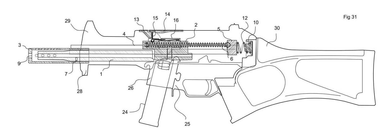
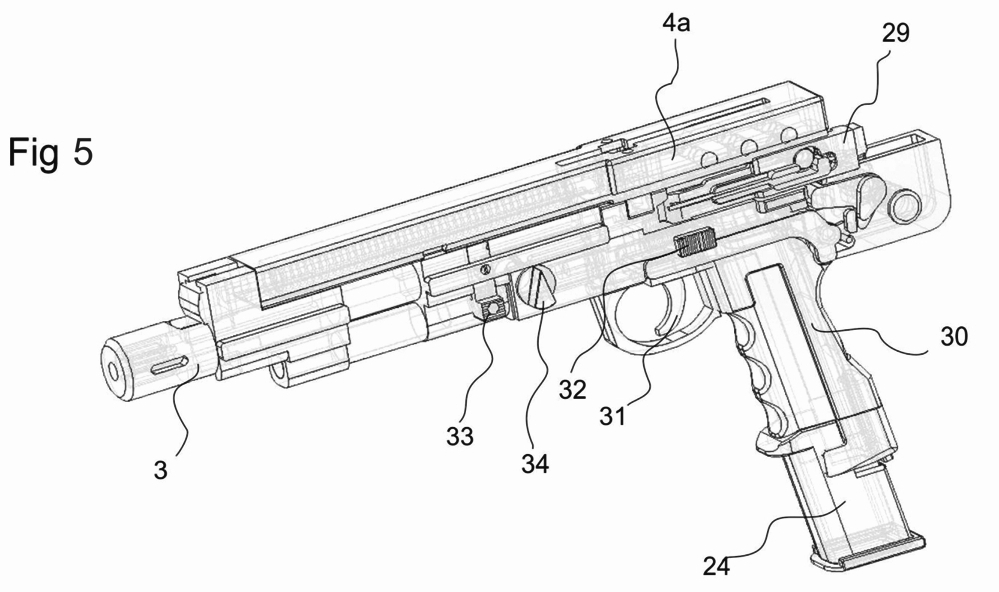
- -- The modular, blowback operated with check point delay, military submachine guns with interchangeable barrels for cartridges: P++; 10мм Auto и 5.7*30 special. As an example - Fig31.
- --
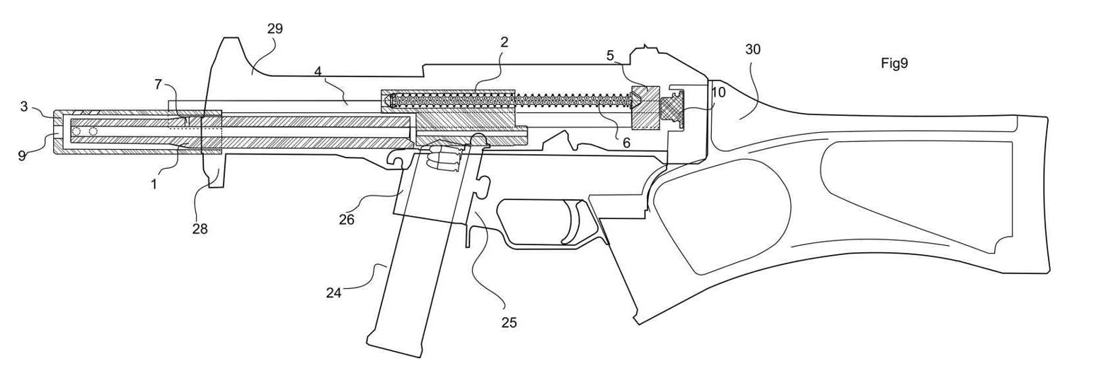
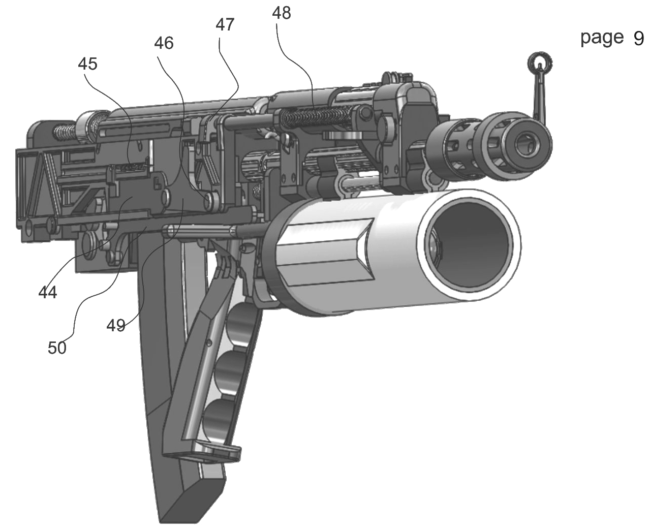
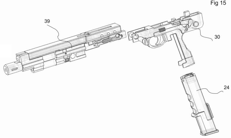
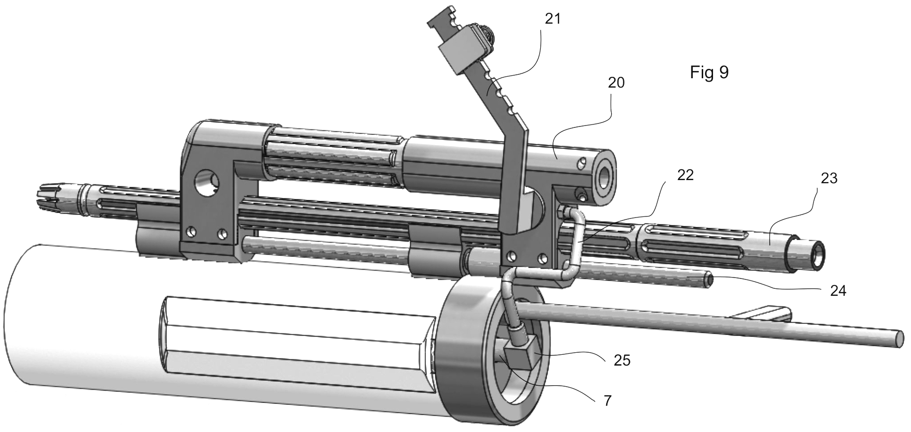
The civil, modular, self-loading carbine with interchangeable barrels and removable breech block for cartridges: TT/mauzer 7.62; P+; .45ACP и .40S&W. As an example - on basis of Fig9.
- -- The blowback operated with check point delay firearm for cartridges: TT/mauzer 7.62; P+; .45ACP и .40S&W on basis of Beretta. As an example - Fig32

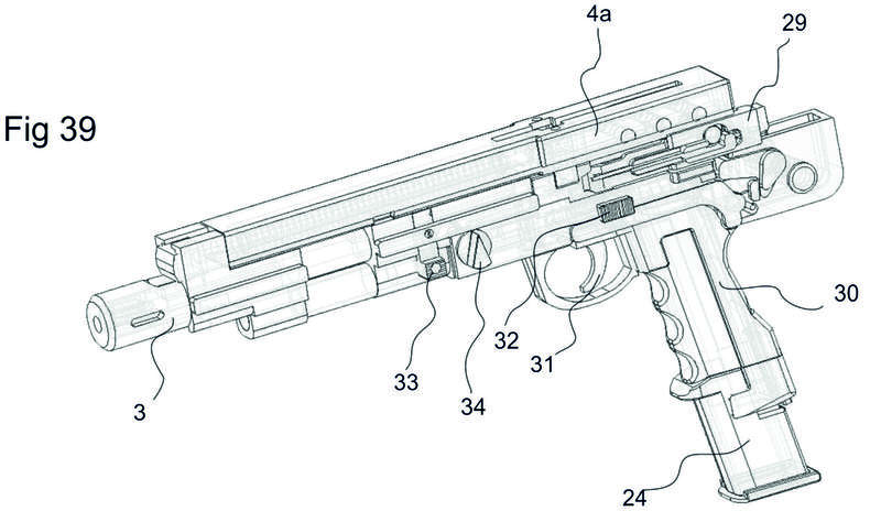
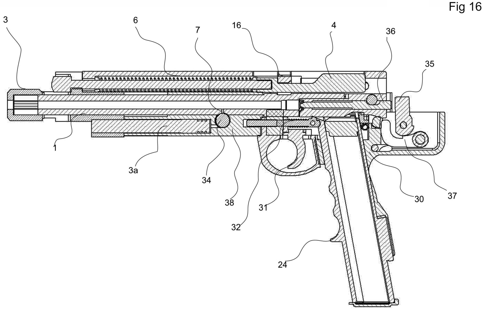
3 - gas brake; 4a - slider; 24 - magazine; 29 - extractor; 30 - module of trigger mechanism and handle; 31- trigger; 32 - lock of magazine; 33 - lock of safety cocked; 34 - gas adjuster and assembler
Comparing of the graphs shows that, at each instant, the vector of moment of inertia on graph P1 of a conventional reloading mechanism is greater than the vector of moment of inertia on graph P2 of the claimed reloading mechanism and closely spaced vectors of moments of inertia of the claimed reloading mechanism are in an antiphase. Fig8
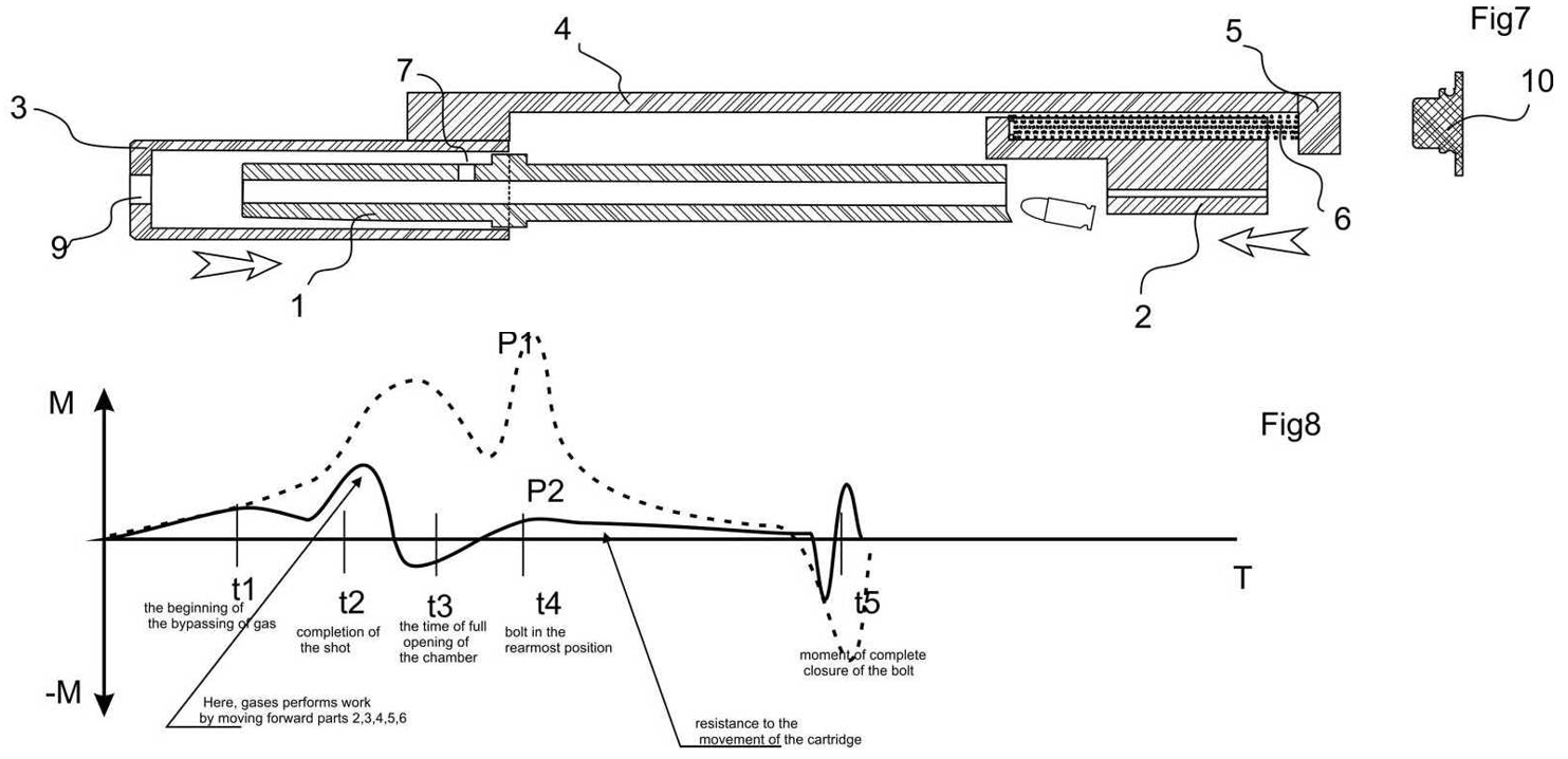
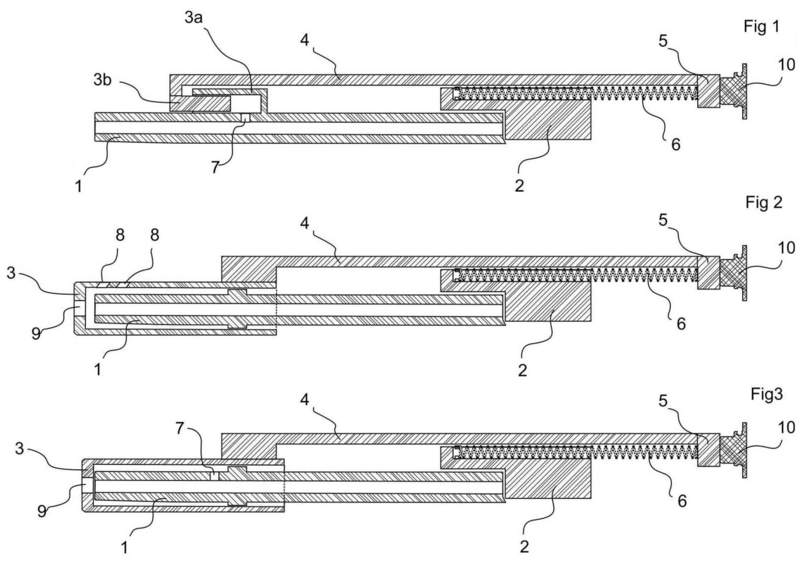
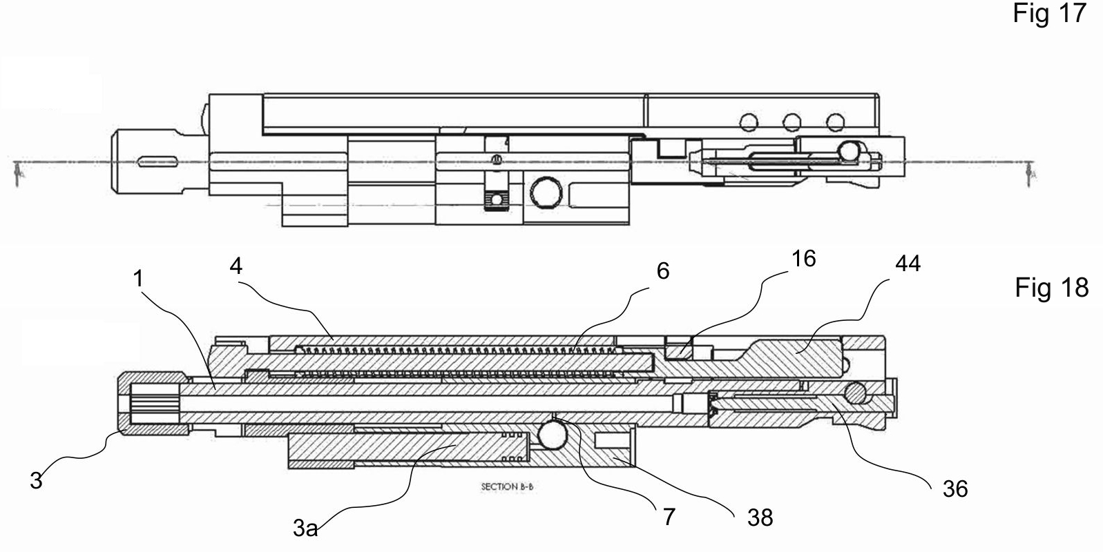
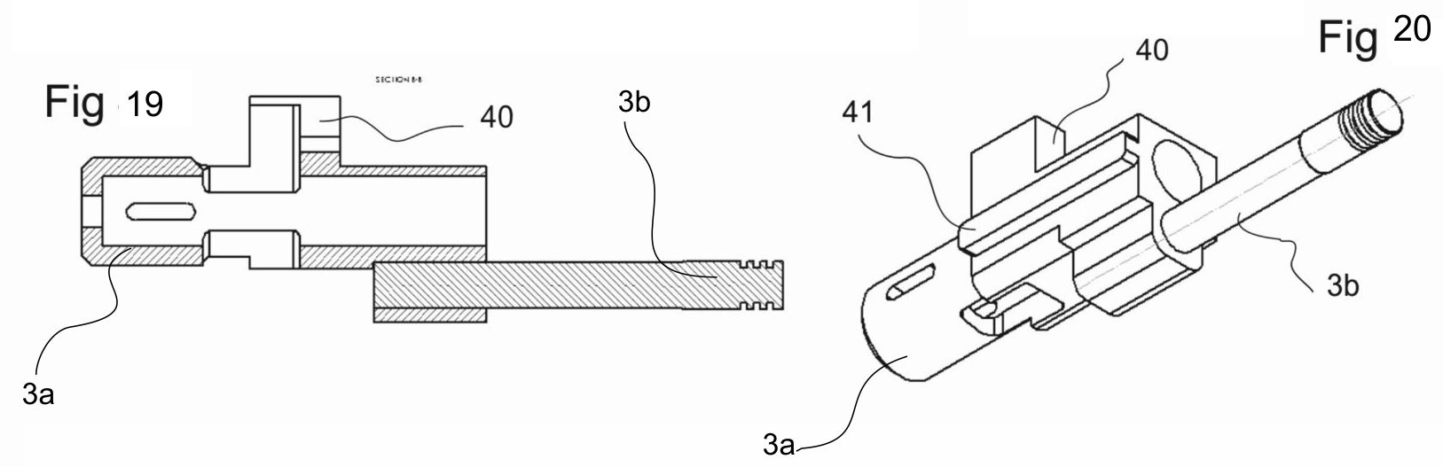
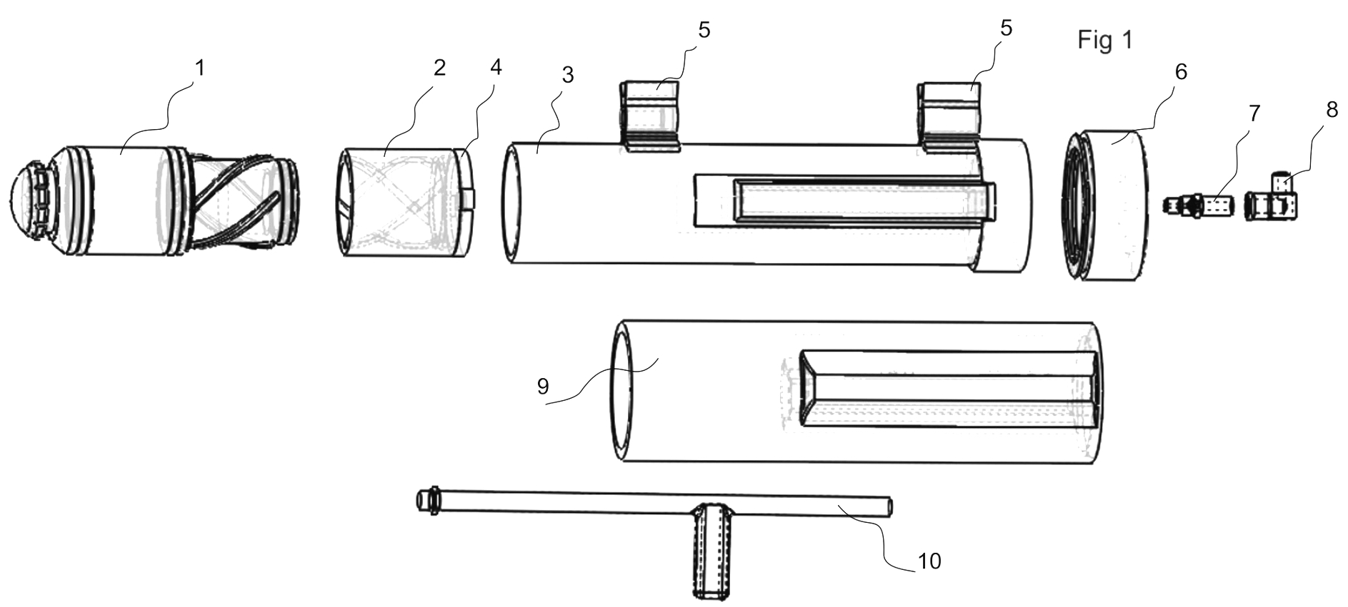
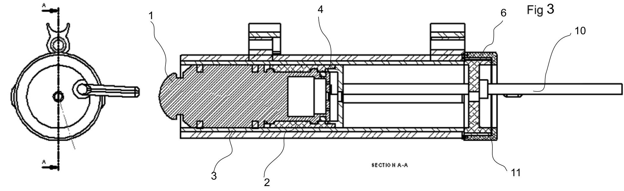
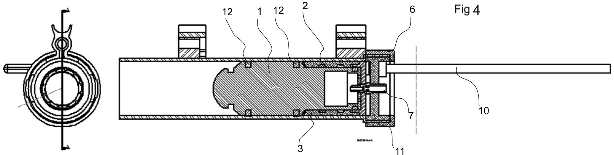
1 - barrel; 2 - bolt; 3 - gas brake; 4 - movable part (slider); 5 - supportive platform for recoil spring; 6 - recoil spring; 7 - aperture for gas bypass; 8 - aperture of gas brake; 9 - outlets of the gas brake; 10 - shock damper; P1 - a conventional blowback; P2 - the blowback that works in manner stated in the Claim 1; M - vectors of moments of inertia; T - vector of time; t1 - start of bypass of gases through aperture 7; t2 - moment of completion of shot; t3 - moment of total opening of chamber ; t4 - bolt in extremely back position; t5 - moment of total closing of chamber
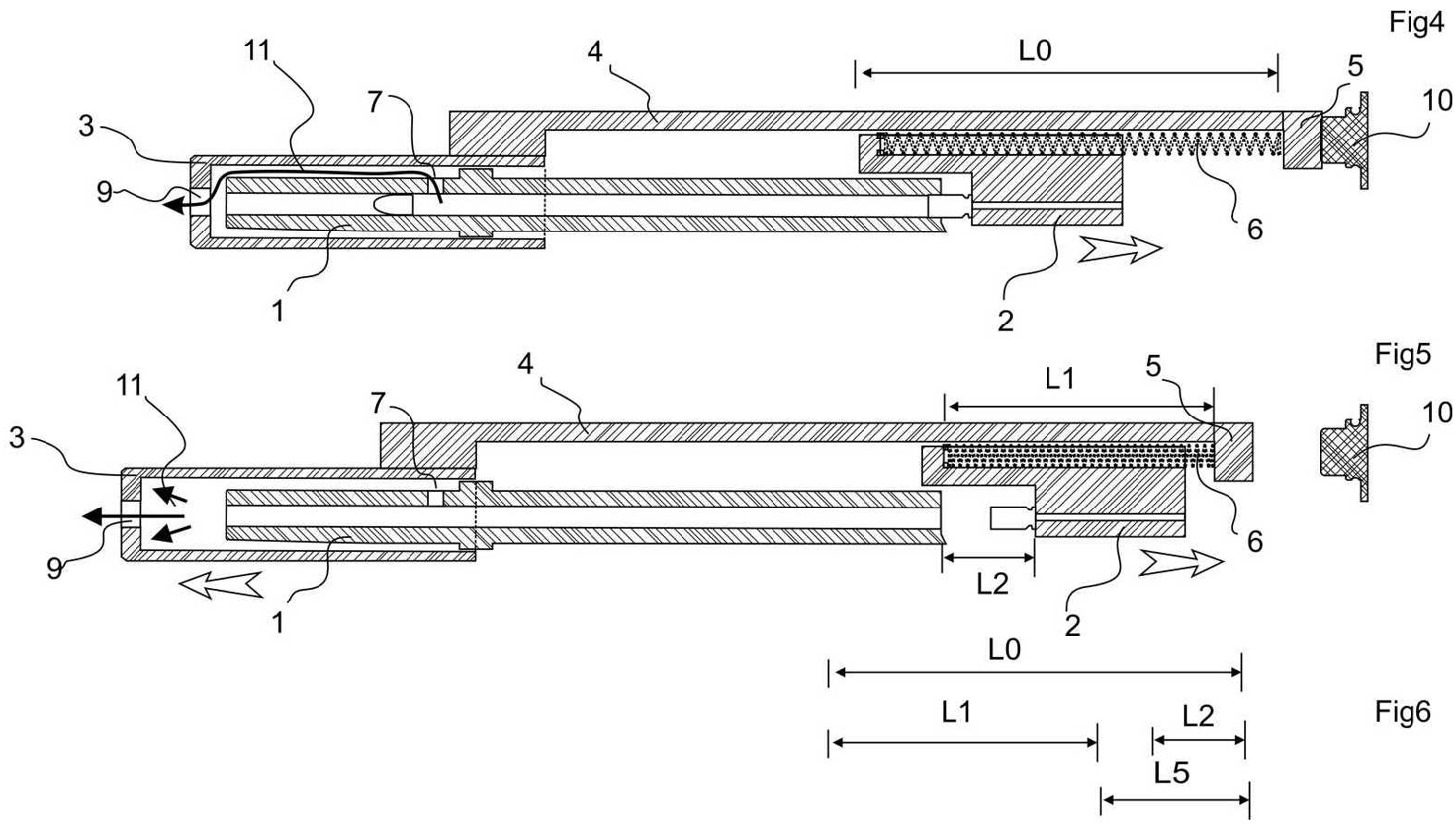
2 - bolt; 3 - gas brake; 4 - slider; 5 - supportive platform; 6 - recoil spring; 7 - aperture for gas bypass; 10 - damper; 12 - spring of damper; 15 - spring of locking block ; 16 - locking block; L0 - overall length of recoil spring; L2 - length of recoil spring in present time; L1 - stroke length of bolt in present time.
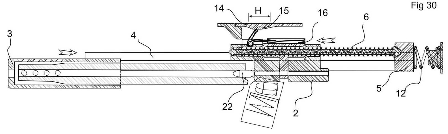
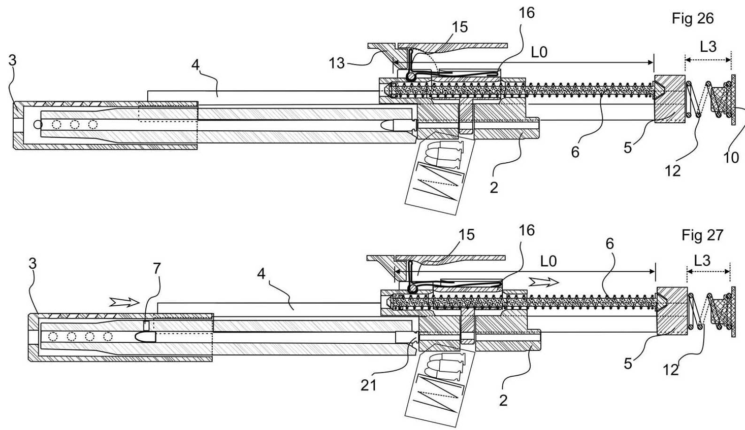
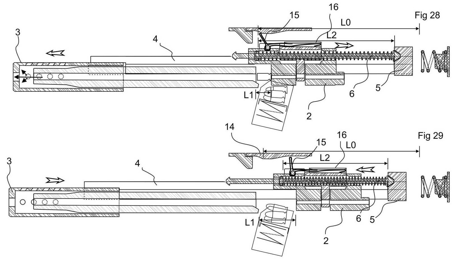
2 - bolt; 3 - gas brake; 4 - slider; 5 - supportive platform; 6 - recoil spring; 7 - aperture for gas bypass; 10 - damper; 12 - spring of damper; 14 - adjuster 15 - spring of locking block ; 16 - locking block; L0 - overall length of recoil spring; L2 - length of recoil spring in present time; L1 - stroke length of bolt in present time
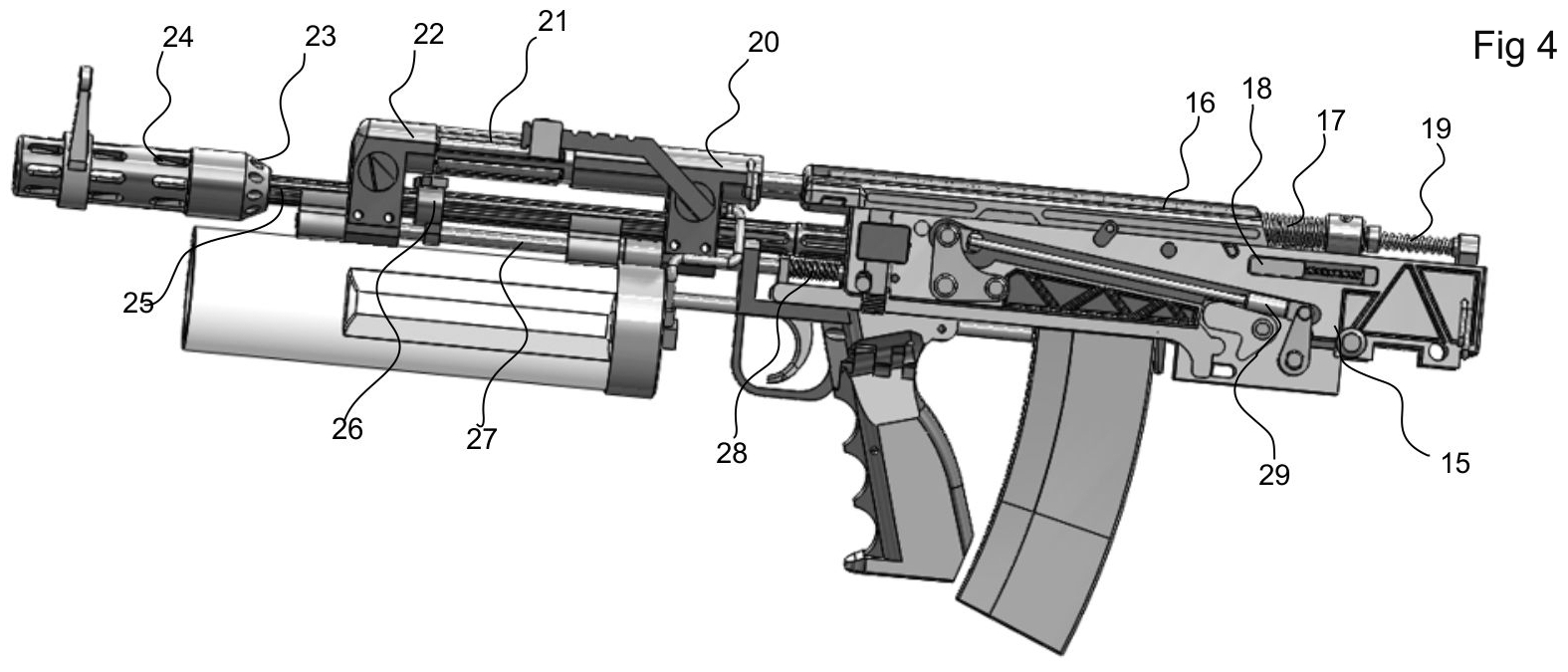
Patent application named:
The proposals which are given into the patenting process:
- --
The design of an automatic, gas operated weapon in which the recoil spring is supported on mobile parts or on combined unit that moves under the influence of powder gases in the direction of shot - as claimed in my patent application - nn 2,960,545 and unlocking of breech block is carried out by influence of gas piston moving in the direction of the shot under the action of the powder gases of the shot.
- -- The design of module of an automatic, gas operated assault carbine that carries out by the proposed in item 1 in which, for the flexible adjustment of the reloading process, two gas chambers which sequentially (during the time) acting in opposite directions on the gas piston are used.
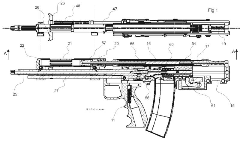
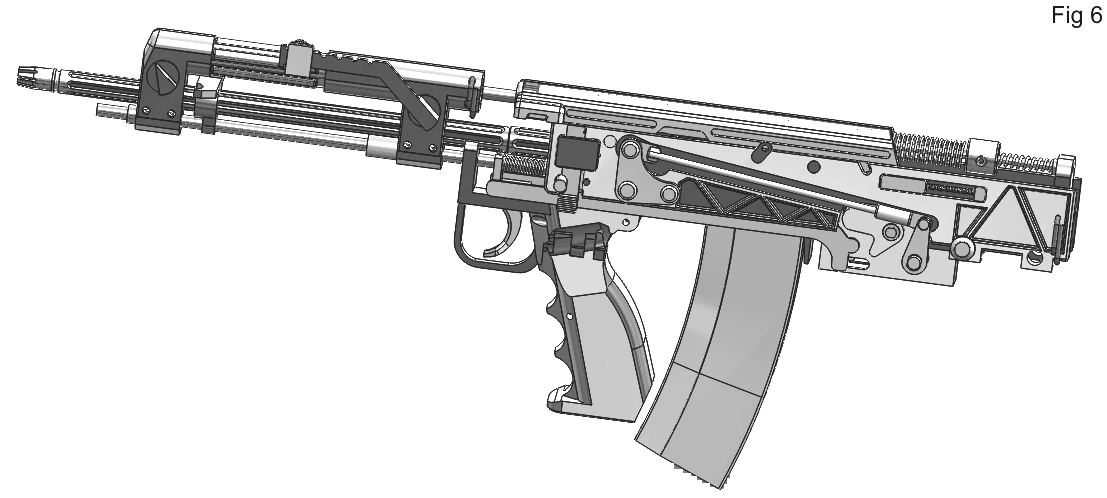
- -- The assault carbine designed as "bullpup" in basis of the module that declared in items 1and 2, in which grip can located near center of gravity as it is adjustable and can be deviated from the vertical position, to the right or left, depending on with which arm a user carries out shoot.
- -- The design of the submachine gun module that carries out by the proposed in item 1, in which the main grip's surface, that is holded by the user's hand, is formed by the magazine being inserted into the simplified frame of a grip.
- -- The design of module of an automatic, gas operated assault carbine that carries out by the proposed in item 1 in which, for the flexible adjustment of the reloading process, two gas chambers which sequentially (during the time) acting in opposite directions on the gas piston are used.
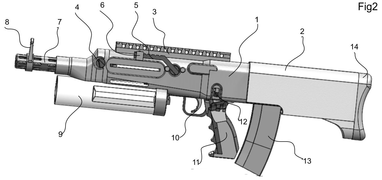
1 - outer shell; 2 - buttstock; 3 - mounting bar and assembling lock; 4 - firing rate accelerator/adjuster; 5 - safety lever of grenade launcher and adjustable basis for rear grenade launcher sight; 6 - rear grenade launcher sight; 7 - muzzle brake and air injector; 8 - front grenade launcher sight; 9 - grenade launcher ; 10 - trigger; 11 - pistol grip; 12 - safety catch; 13 - magazine; 14 - buttstock dumper

Patent application named:
- --
For reducing recoil force it work in manner "fire-out-of-battery";
- -- Composite barrel consist of three main parts - of light weight low pressure barrel (hereinafter LP) and a medium pressure barrel (hereinafter MP) integrated with a high pressure barrel (hereinafter MP) which form a joined moveable chamber that moves inside of a LP barrel;
- -- Loading of a grenade carries out from a muzzle when movable composite chamber is put forward into loading position;
- -- During of shoot, when the grenade leaves the chamber, this chamber changes direction of movement to forward at movement to rearward and compensates and dumps recoil forces arising of grenade leaving from LP barrel.;
- -- Composite barrel consist of three main parts - of light weight low pressure barrel (hereinafter LP) and a medium pressure barrel (hereinafter MP) integrated with a high pressure barrel (hereinafter MP) which form a joined moveable chamber that moves inside of a LP barrel;
The proposals which are given into the patenting process:
- --
The grenade is inserted into the rifled moveable chamber only by rear part having high- pattern ready rifling.
- -- All of a propellant charge is located inside rear part of the grenade.
- -- The propellant charge is ignited by means of usage of outward powder gases
- -- There is a charging cuts on front side of the grenade
- -- All of a propellant charge is located inside rear part of the grenade.
2 collage